JoeTR6
HalfDork
8/25/16 9:13 p.m.
Another part order and more progress. I got a new cam, installed and timed it. This should make my right foot much happier. I also got the new rocker shaft. Unfortunately, I got a little heavy handed with a hammer. See if you can spot the problem.
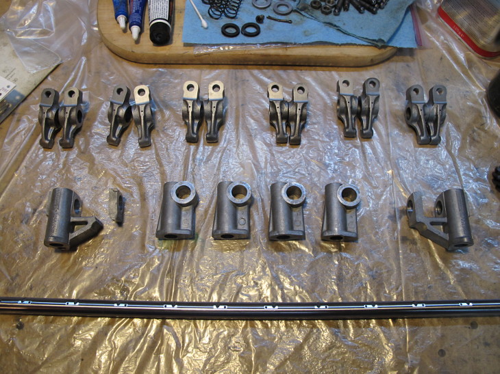
I was tapping the left side rocker pedestal onto the shaft and it kept getting tighter. Upping the ante cracked the narrow end from the pedestal. I have a spare rocker assembly, so it's not a huge problem. I'm just usually more careful with aluminum parts. The new shaft is 0.002" thicker than the original one (actually, the original one varies a lot), so some of the pedestals are pretty tight. I tried drilling the broken one out with a 9/16" drill, but that's too big by 0.003". Some careful filing may be the best bet.
I also did some testing with the POR 15 engine paint. That stuff is nice to work with. It flows well and covers in one coat. I may paint something destructible to test its durability, but here's the distributor mount that I painted.
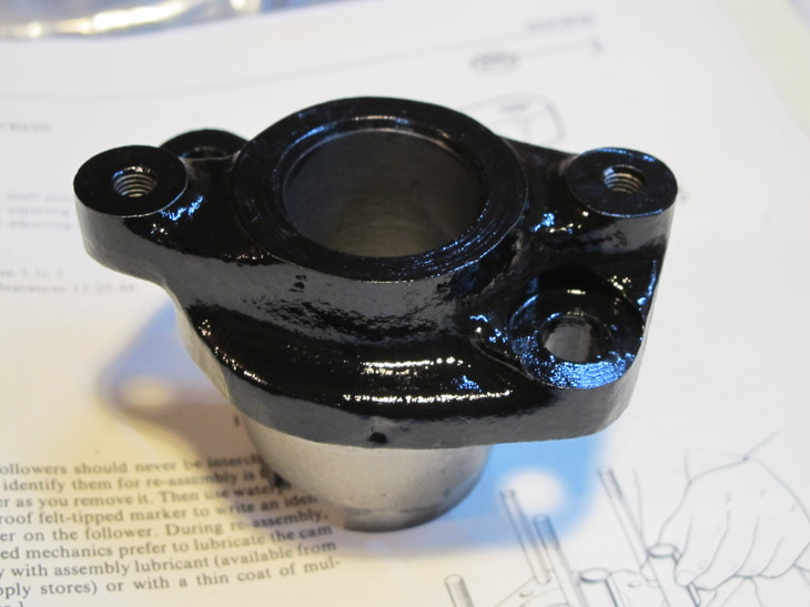
I originally tested it on a chunk of scrap angle iron. Then beat it with a hammer, blowtorch, and any readily available chemicals.
You can hurt it. But you gotta get stupid.
Could you turn the offending rocker shafts on a lathe more accurately than a file?
JoeTR6
HalfDork
8/25/16 9:40 p.m.
Dusterbd13 wrote:
I originally tested it on a chunk of scrap angle iron. Then beat it with a hammer, blowtorch, and any readily available chemicals.
You can hurt it. But you gotta get stupid.
Could you turn the offending rocker shafts on a lathe more accurately than a file?
That paint is pretty nice. Thanks for pointing it out.
I'd rather bore out the pedestal hole than turn the rocker shaft, although the shaft is surface hardened down to 0.40". One of the middle pedestals is tight, and I'd rather not alter the shaft as this makes a few rocker arms too loose. Worst case, I can buy Richard Good's rocker pedestals for $129, but the price of this project is already creeping (or leaping) upwards.
JoeTR6
HalfDork
8/27/16 8:19 p.m.
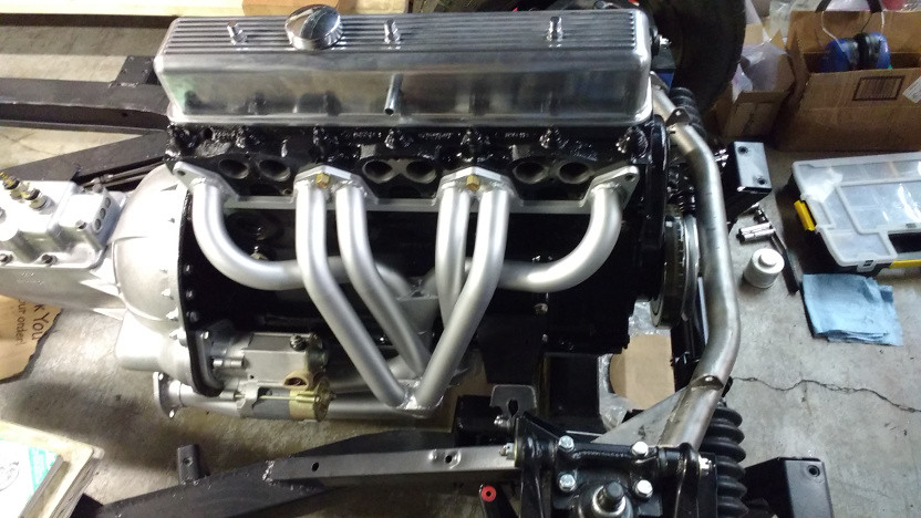
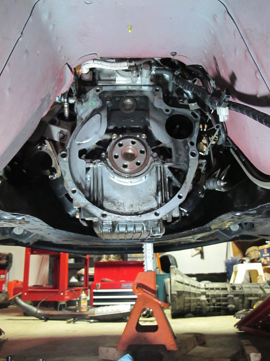
With the cam in, the engine build could proceed. The top of the block was fairly clean, but needed a little solvent love. The tappets were lubed and inserted. Then the ARP head studs went in followed by the gasket.
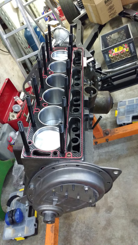
Everything looked good so I cleaned up the head. This particular head was on a friend's autocross car before we decided to fuel inject it. It's an early head with the narrow inlet port spacing, but we needed a wide port head to match the intake. Before we learned this, the head was already rebuilt and ready to bolt on. That was two or more years ago, but it's still in good shape. So I wiped it down, blew it clean, and torqued it on.
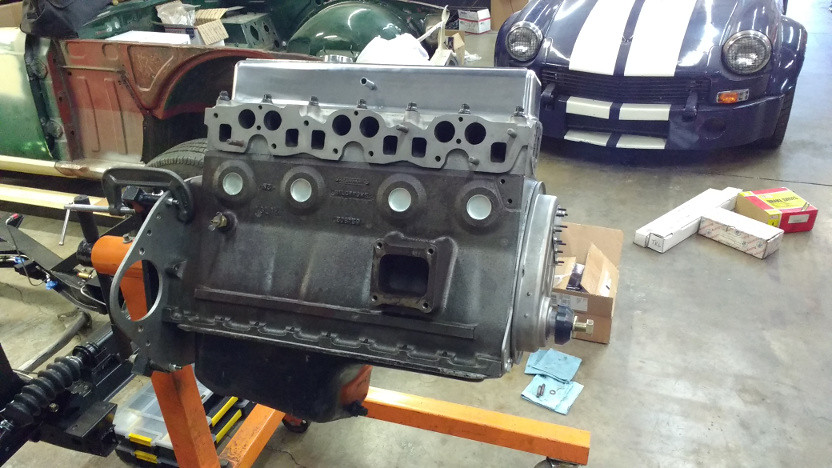
Now it looks like an engine. After blocking off a few holes, it should be safe to wire brush and etch the block in preparation for paint.
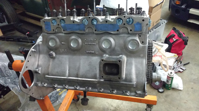
In talking with the same friend today, I learned that the end rocker pedestals are prone to fracturing where mine did. Granted, I helped it along. But we know someone that had one break while driving. When this happens, you lose an exhaust rocker and are stuck. I have all the stock pedestals fitted and cleaned up, but am going to use new aluminum ones. The stock ones are actually made of a light pot metal. The aluminum ones all clamp down on the rocker shaft instead of relying on a single set screw to hold the shaft in place. If this screw comes loose, you lose all oil flow to the head. Not worth the risk with the way I'll be driving this car.
JoeTR6
HalfDork
9/4/16 9:14 p.m.
After several hours of work, the engine is ready for paint.
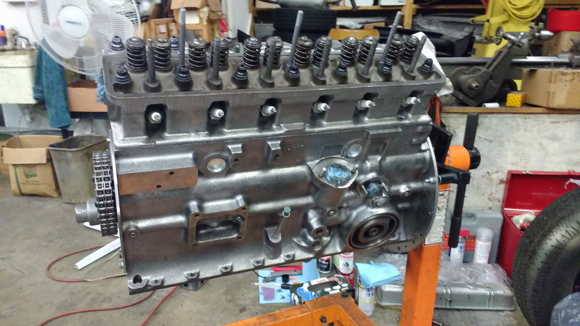
That was seriously not fun. I put on all of the covers/blocked the holes and degreased the block with brake cleaner. Then I used a wire brush and paint stripping disk on a drill to remove most of the rust. On the right side, shop towels soaked in a mild phosphoric acid solution were laid on the block for an hour to etch some heavier rust. A clean light duty wire brush polished things up, then more brake cleaner until the shop towels would stay relatively clean. This better be clean enough because I'm out of patience.
The left side was wire brushed and soaked in WD-40 when I first got the block back. That was by far the easiest side to clean. There was very little visible rust, but a lot of dirty oil to remove. I wish I had done both sides like that.
Paint goes on tomorrow morning.
JoeTR6
HalfDork
9/5/16 8:07 p.m.
The engine is now the proper color.
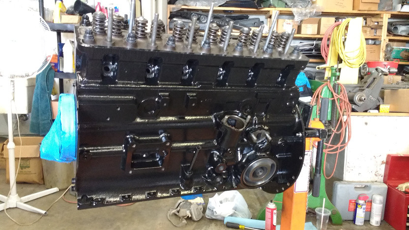
I also fit the completed rocker assembly but didn't have a feeler gauge to set valve lash. A bunch of stuff that goes on the engine was bead blasted and will get painted this week. Next weekend should be when everything gets bolted together and dropped onto the frame. Getting past this point feels like a huge win.
I was debating what needs to get done to the motor so that it survives the next 6 months or so. It's going to take at least that long before it's running. I was thinking squirt some oil in the cylinders and maybe run the oil pressure up by turning the oil pump with a drill. The latter may just displace the assembly lube, so should wait until it's time for first start. Getting the drive train complete on the frame will signal the next project phase of getting the body painted.
JoeTR6
HalfDork
9/10/16 6:47 p.m.
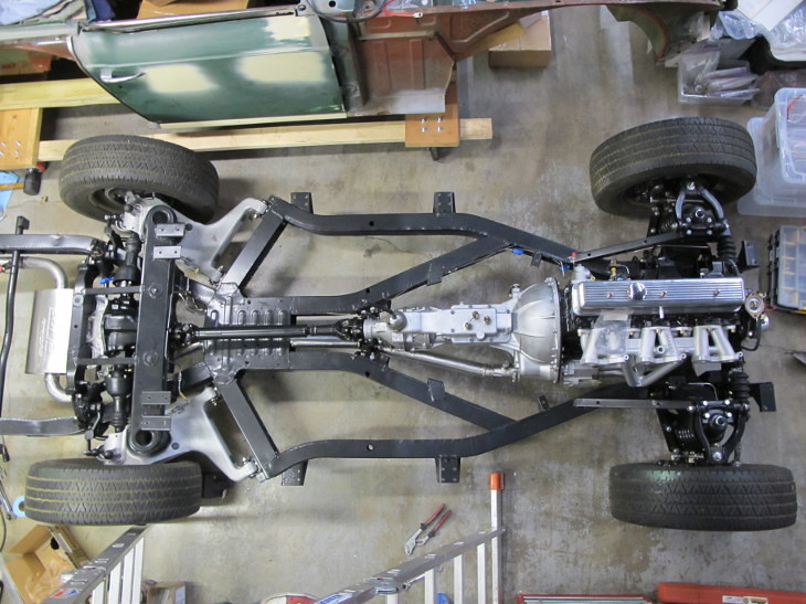
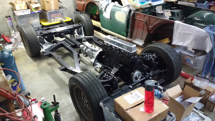
The engine got buttoned up today.

There was a lot of stuff that I had to dig up in random boxes, so this took longer than it should. The oil pan needed to have two of the front flange holes ovaled to match the block. Since I forgot to order a box of 3/4" long 3/8-24 bolts, the engine mounts didn't get bolted up and progress towards mounting this on the frame came to a halt.
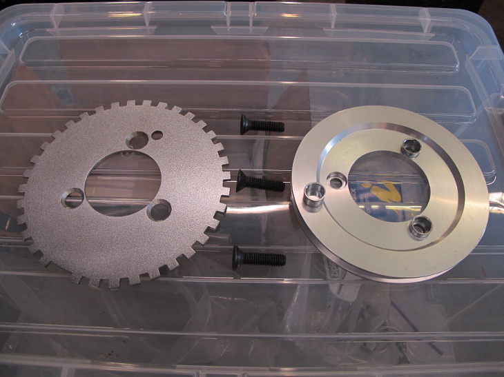
So instead I came up with a plan for mounting a trigger wheel. I ordered a 6.75" toothed wheel from diyautotune. If there's room in front of the pulley, I'll use longer mount bolts and spacers to hold it on. The issue may come down to whether the bolt heads will clear. I may need to use button screws or even countersunk allen screws to hold the trigger wheel on. It should be accurately centered by the tapered crank bolt adapter that replaces the fan extension after a properly sized hole is made in the wheel. Let's hope the engine can be mounted far enough back. Otherwise I will need to get creative and do something with the flywheel to act as a trigger.
JoeTR6
HalfDork
9/11/16 7:17 p.m.
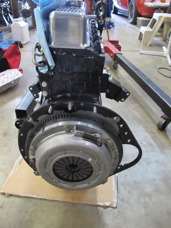
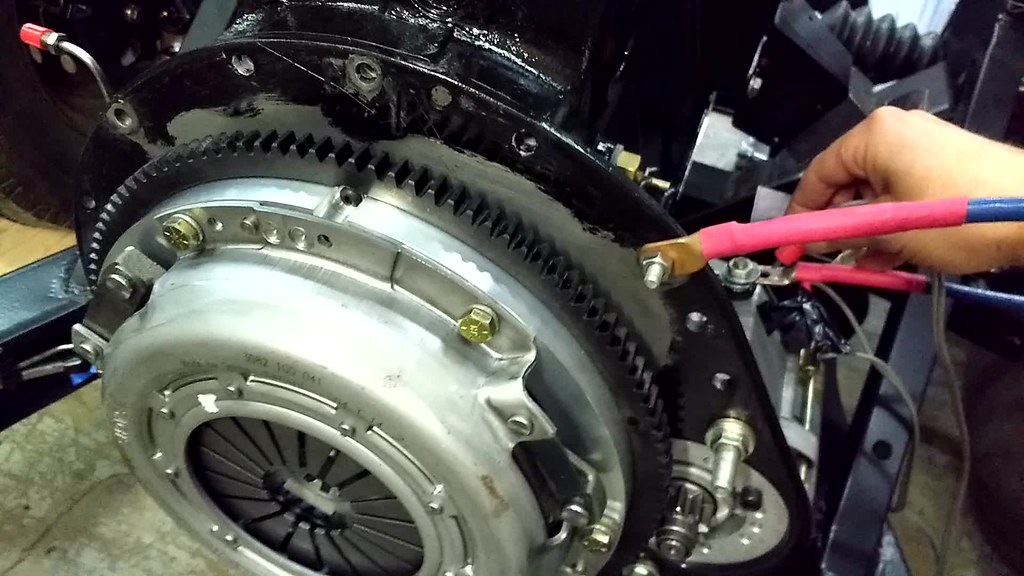
This is the fun part of this project. Bolting major assemblies together is much better than removing rust and grime. The flywheel and clutch was bolted on. I'm using a Sachs pressure plate from a Saab 900 with an AP Racing clutch disk on an aluminum flywheel.
It took two tries to get the gearbox mated to the engine. The clutch disk was a close fit on the input shaft and I didn't quite have it lined up on the first attempt. The second try took less than a minute. With the engine and gearbox bolted up, it was time to hoist them onto the frame. The release valve on our engine hoist is a bit twitchy, so this took some careful manipulation. No damage done, and it's on the frame.
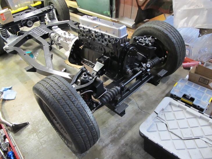
I didn't have time to check clearance in the front, but it looks tight. The steering rack will need to move just to get the crank damper in place. I may be able to move the engine back 1/8" or so by levering it, but that's pretty much where it wants to be stock. If I modify the rear mount, the front mounts would allow it to go back further, maybe as much as 1/4" or more. But then the firewall and shifter (and possibly driveshaft) limits how far it can go. We'll see.
JoeTR6
HalfDork
9/13/16 7:06 p.m.
Looking over some pictures I took this weekend, it struck me that I didn't wipe the extra torquing lube from the flywheel bolts. There's not a lot of extra grease, but some of it could end up on the clutch.

Worst case, the clutch will start slipping and I'll pull the gearbox. I'll take my chances. It's more likely the rear engine seal or gearbox front seal will soak the bellhousing.
JoeTR6
HalfDork
9/18/16 7:48 a.m.
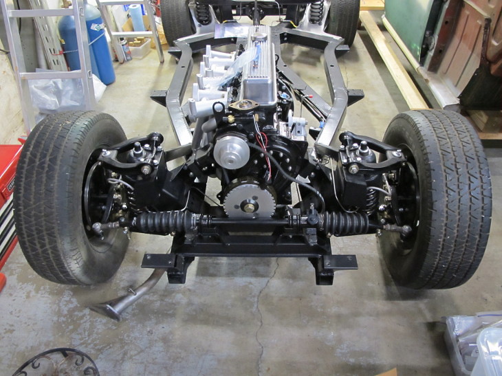
Sometime this week the steering rack was unbolted to fit the crank damper.With the engine in the stock position, the steering rack couldn't be bolted in even without the trigger wheel. Jacking the overdrive off it's mountings let me lever the engine as far back as the front mounts will allow. This moves the engine back about 3/8". With this change, here's where things sit.
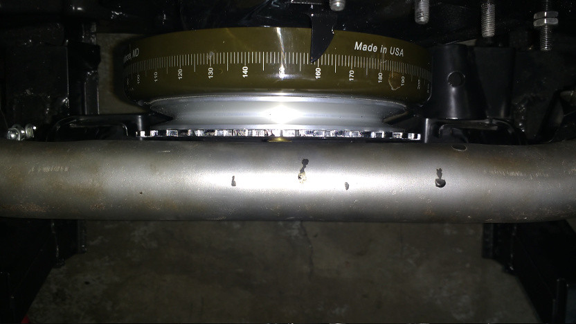
For scale, the trigger wheel is 1/8" thick. So I have 1/8" of clearance. The steering rack has about 1/4". If I hold the trigger wheel and pulley on with countersunk bolts, it may fit. But I'll need to move that crossmember tube forward in case the engine moves longitudinally. Another option is getting a damper shell with integrated trigger wheel, but that is more $$$. It wouldn't hurt to give ATI a call to see what the options are.
Here's how it looks from the front.

JoeTR6
HalfDork
9/20/16 11:23 p.m.
I got sidetracked when trying to fit the driveshaft. The driveshaft flange didn't match the overdrive flange raising a red flag. I had a suspicion that the overdrive wasn't for a TR6. Referencing the serial number "25/115835" indicates it's actually a Triumph 2000 overdrive according to John Esposito at Quantum Mechanics. So the speedo gearing and output flange are different from a TR6. I can deal with the speedo calibration, and the flange is a $50 exchange with Quantum, so not too much cash is involved.
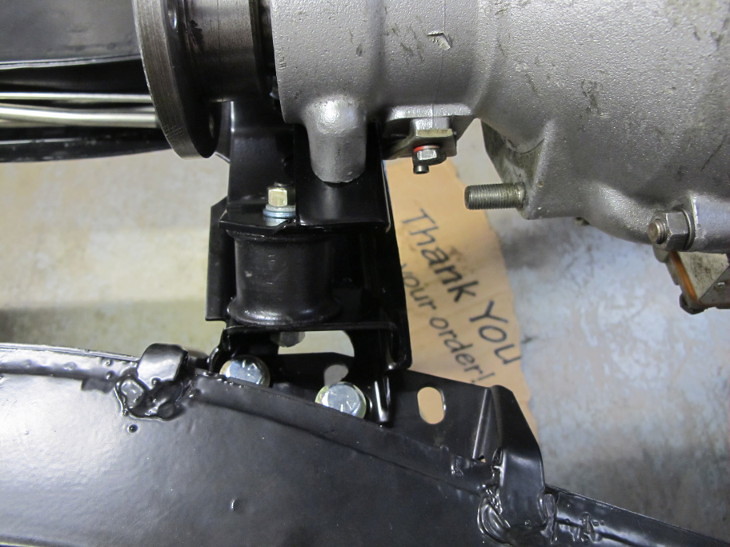
The modified gearbox mounting is done. It doesn't look too much different from stock.
I couldn't help myself and fitted the starter and header. I needed to check the fit of the header with the starter and also should test the starter engagement before the body goes on.
JoeTR6
HalfDork
9/25/16 5:18 p.m.
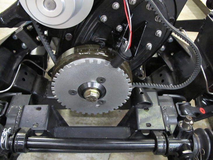
I finally mounted the trigger wheel onto the front of the damper/pulley. One of the button screws I bought to mount it was metric, so I had to improvise with a temporary countersunk. Spacers were cut to go around the bolts so that they will hold torque.
It's a good thing to have access to a lathe. The centering hole needed to be 2.336" in diameter, so it was cut on a lathe and the edge cleaned up. It took a few passes so that the tapered nose piece would exactly center the wheel with it flat against the pulley. The pulley needed a slight bevel cut where it centers on the damper so that it laid completely flat.
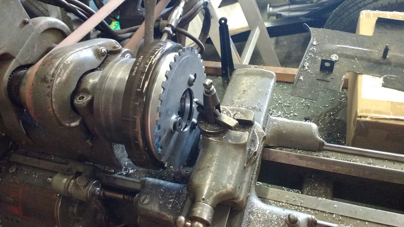
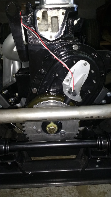
After that, the outer edge was trued up. There's just a slight bit of wobble and no runout in the trigger wheel. With that done, it was mounted on the engine and a bracket for the sensor fabricated. It didn't turn out bad, but still needs to be trimmed down some. Here's where everything ended up. There's not much clearance, but it should be enough.
![]()
JoeTR6
HalfDork
9/28/16 10:13 p.m.
My overdrive speedo gear is off more than I'd thought. The TR6 used a 20 tooth pinion and 8 tooth shaft gear for a 2.5 ratio. A Triumph 2000 used a 18 tooth pinion and 5 tooth shaft gear for a 3.6 ratio. That's a lot of speedometer error, and I don't think recalibrating the speedometer will fix the odometer error (I could be wrong). Even if it can, that's more money than replacing the speedo gears in the overdrive. But the overdrive has to come apart. Lesson learned: Don't assume anything.
Since I'll be running shorter tires than stock, my plan was to use the 21 tooth pinion from a Volvo J-type to increase the ratio by 5%, pretty much countering the tire size difference. Looks like I'll be ordering some gears with that new rear flange.
JoeTR6
HalfDork
10/8/16 8:32 p.m.
There hasn't been much progress on the TR6 because I've been doing this.
I had a freak failure of the starter in my MSM where a few of the starter pinion roller bearings fell into the bell housing. I'm using this as an opportunity to freshen the clutch, lighten the flywheel, and replace the oil seals.
As for the TR6, the gearbox was pulled and overdrive re-disassembled. This time, I had to remove the rear annulus bearings to replace the speedometer drive gear. Maybe this was fortunate, because the rear bearing feels a bit rough and catches occasionally. I tried cleaning it, but that didn't help much. It's not an expensive bearing (~$20). I have two 20 year old but unused 4-speed tail shaft bearings from previous rebuilds that are SKF 6206 made-in-the-USA bearings. The question is are these the same as the J-type overdrive tail bearing? Dimensionally they are identical to the old bearing, but The Roadster Factory catalog shows different part numbers. Moss, however, sells the same part for 4-speed and overdrive tail bearings. I think I'll risk it to avoid using a newer bearing that will probably fail sooner than later.
/>
Meticulous, beautiful work as always- it looks as clean as a model.
Question, is the trigger wheel in anticipation of Fuel Injection, or timing only? I remember from earlier in the thread that you were building to a class, but maybe said to heck with it, and went restomod when the cam became an issue? Whatever you are doing, it's NICE.
JoeTR6
HalfDork
10/9/16 2:40 p.m.
I'm definitely going to Megasquirt this thing with fuel injection. FSP rules are that the intake is completely open to modification. In truth, I bumped myself out of FSP when I put the non-stock cam in. I could have bought a new late stock cam (the early cam has less lift and duration), but then it would need to be paired with a late head (which would need to be completely rebuilt, including hardened valve seats). Basically, I need a stock long block from one particular year of production. If I were serious, the obvious choice would be to find a TR250 motor as it made the most power of any year 6 cylinder TR. But it's fairly rare, and I don't want to start over. So yeah, I'm going for fun to drive at this point.
JoeTR6
HalfDork
10/9/16 5:44 p.m.
Another thought I've had lately is to build my MSM into a BSP car. They can be made very competitive. None of the mods I've made so far are illegal, and the new clutch/flywheel move me in the right direction. I'd really need to use E85 to get the most out of the stock turbo, but 220 hp should be doable. The only other thing I need to do at this point is to throw on some quality coil-overs and get an autocross alignment and corner weighting.
JoeTR6
HalfDork
10/12/16 2:29 a.m.
I'll never complain about working on a TR6 frame without a body again. I just spent another night crawling around under the MSM. All of the important stuff is back in, but it's a little too late (early?) to see if it starts without the exhaust hooked up. I've done a load of stuff that was overdue, such as replace the fuel and air filter and swapped the clutch fluid. The clutch feels very smooth with just a hair more effort than before. A new front sway bar is arriving tomorrow to fix the oversteer issue this car has when autocrossing. I'll change out the sway bar end links while that gets installed tomorrow, er, tonight.
Someone is borrowing my welder, so progress on the TR6 has ground to a halt. I need to weld a small crack that I made in the overdrive case while straightening the hole where the speedo drive gear goes. It took a hit at some point making removing the pinion gear difficult. I have no time to spend on it anyway as the MSM is priority one right now.
JoeTR6
HalfDork
10/20/16 8:36 p.m.
Back to the overdrive. I received the TR6 speedo gears and drive flange, so proceeded to tear the overdrive apart (further this time). The rear part of the overdrive is back together with a new tail bearing.
I wanted to check the condition of the pressure relief valve, dashpot, and pressure filter. The pressure filter was not looking so good.
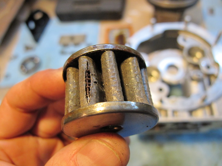
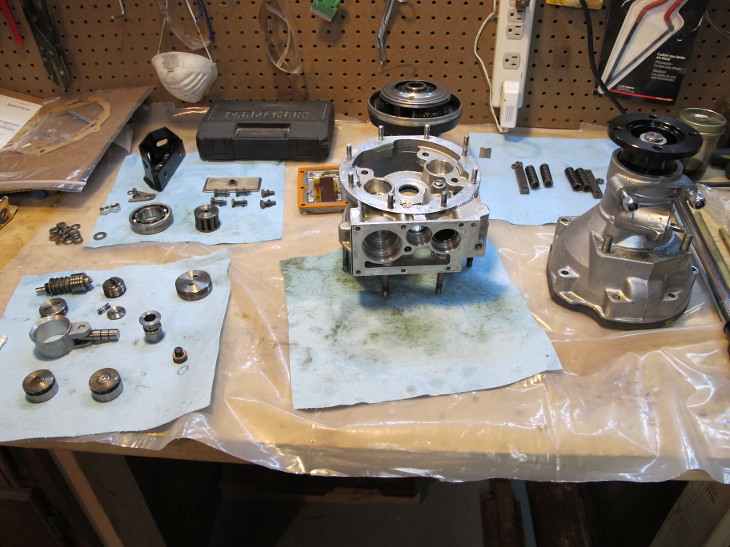
Hopefully a new one will arrive on Saturday. If not, the hydraulic guts of a J-type overdrive are easily accessible from underneath. That's the big advantage of this unit over the earlier A-type which had to be torn apart to access this stuff. There was a bit of metal swarf in the internal cavities, so doing this was definitely a good thing. Before I reassemble the overdrive, I'm going to tear into my Volvo overdrive to see if it's internals are in better shape. The clutch may indeed be less worn, and the parts should be interchangable.
JoeTR6
HalfDork
10/23/16 7:40 p.m.
It was a long weekend of fixing cars. First, I finished getting my MSM back to daily driver status with a new clutch/flywheel and a new front sway bar. Then the overdrive was put back together after tearing it all the way down. I ended up replacing most of the o-rings. A lot of time was spent attempting to reduce oil leaks (I know, silly me). The overdrive and gearbox were bolted together with surprisingly little drama.
Before fitting the gearbox (again), I wanted to check the starter. No worries.
I cleaned the assembly grease off the flywheel before bolting in the gearbox. The install went fast; everything just lined up. With that done, I finally bolted up the driveshaft.
Next is the exhaust, radiator pan and front sway bar.
JoeTR6
HalfDork
10/29/16 12:31 p.m.
A major reorganization of my spare parts mess is underway. I've been dropping things into boxes and tubs for 25 years, and acquired another random pile of parts with this project. Now it's time to figure out what I have and what's missing. The missing parts at the moment are the little clamps that hold both the intake and exhaust manifolds down. But there are a bunch of things that I'm going to need over the next year and can't afford to spend hours looking for each one. Neither fun nor interesting, but necessary.
JoeTR6
HalfDork
11/2/16 11:57 a.m.
My parts are sorted and I found the small header clamps.
Now for a slight step backwards. The button screws holding the trigger wheel on come very close to the steering rack (within 1/8"). I've decided to use countersunk screws. The heads on these 3/8" screws are roughly 1/4" thick, so half of the countersink needs to be behind the trigger wheel. I should be able to turn some round aluminum stock on a lathe to act as spacers that allow for this. The worst part will be cutting an accurate countersunk hole in the trigger wheel itself. I can mark an accurate location using the button screw heads as a guide.
JoeTR6
HalfDork
11/5/16 8:10 p.m.
Friday I drilled the countersunk holes in the trigger wheel and did a test fit. In spite of my cheap Delta drill press, these ended up in the right place. So now I just need 3/8" long spacers that fit around the bolts and inside the pulley countersunk holes. I'll try to get some pics of this tomorrow when it's assembled.
This part of the project has consumed a ridiculous number of hours. It's the small modifications that sometimes vex you.
JoeTR6
HalfDork
11/6/16 7:04 p.m.
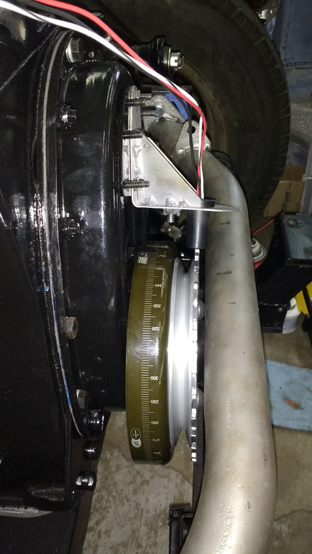
I'm hoping that the front of the engine is done. I found some steel spacers for the trigger wheel that were the perfect diameter and for the most part just needed to be cut to length. A lathe was used to square up the ends and cut a small chamfer on the bolt end and slightly round the pulley end. Here are the parts before installation.
And after. I tried some silver powder coat on the trigger wheel, but it turned out a little too sparkly.
This thing's starting to look like a car.
JoeTR6
HalfDork
11/12/16 8:29 p.m.
Yesterday I test fit the exhaust and had to adjust the midpipe. It was hitting the bottom cruciform plate where it goes through the middle of the frame. It took cutting and re-welding at two joints to make it right.
Another small setback. The diff was leaking more than my 20-year-old restoration, but it should be dry. I used a spray-on gasket sealer that apparently couldn't handle GL-5 gear oil. The diff was lowered without unbolting the driveshafts and I just had room to get the cover off. The flanges were cleaned up and a new gasket sealed with Permatex Aviation #3. Hopefully this will keep it dry for at least the first 10 miles.
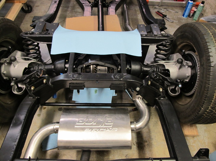
I also finally welded the tail pipe on. My only concern about how everything fits together is that the bend before the muffler is a little close to the lever shock. I can always make a heat shield to protect the shock.
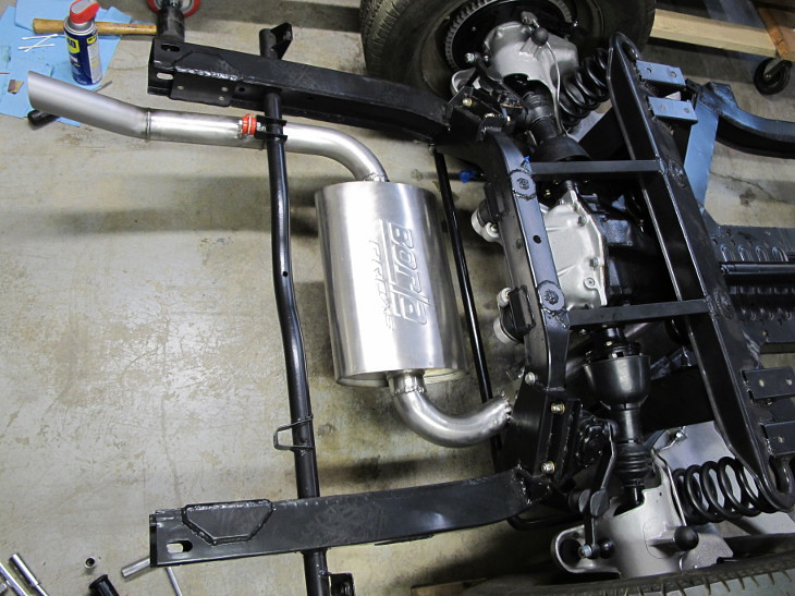
The exhaust is almost done. I still need to make a bracket to hang it from the overdrive unit. I'd considered leaving that off, but it might stress my (hopefully adequate) welds too much. There are a few things to blast/powdercoat on the front and the frame is basically done.