
Morning racers,
No secret our shop does extensive CFD work. With our connections to pro-level racers, we do a lot of projects we can never ever talk about. that's a problem because I'm a blabbermouth. So what we did is a full aero study on my personal car. Our CFD process is highly calibrated. we report data to teams so they can build parts, this reduces the time needed in the wind tunnel, they then provide the data back to us and we calibrate our equipment. it's a never-ending process, just know that data share is why we can't talk about who we are working with, but it's also why our equipment is highly accurate. I'm sure you understand why the little Miata gets a back seat to the top-level cars, and why progress is painfully slow. I just want to talk about it soooo bad. So here is the process.
It's all starts here as you can see
https://www.youtube.com/watch?v=cahak-w3BWE&feature=youtu.be
The car get covered in chalk. This helps our scanning equipment create what's called a "mesh"

as you can see here this is a mesh of a NC Miata and MESH files are basically unusable, not pointless but almost.

once the mesh is imported the engineers begin the painstaking process of turning it into a useable part. From MESH into a body. the CFD computers will only recognize a "body" the day that scanning equipment becomes 99% perfect and we can automatically change a mesh into a solid body our CFD costs will fall 50%. more than half the labor involved in this process. I know your thinking Fusion has a mesh to body converter... it doesn't work on parts this big, but I think it's coming soon.
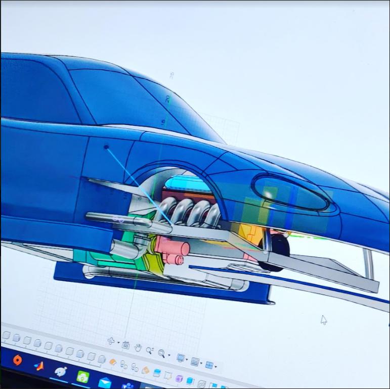
After that, it's time to model the underside and internal parts. Driveshafts, Transmissions, Radiators, and ducts all get their turn being created to mirror the real thing. i'm telling you this is weeks worth of work for each car.

Here you can see the almost finished product. at this point, it has about 40 hours of engineering time and it's shoved into the computer.
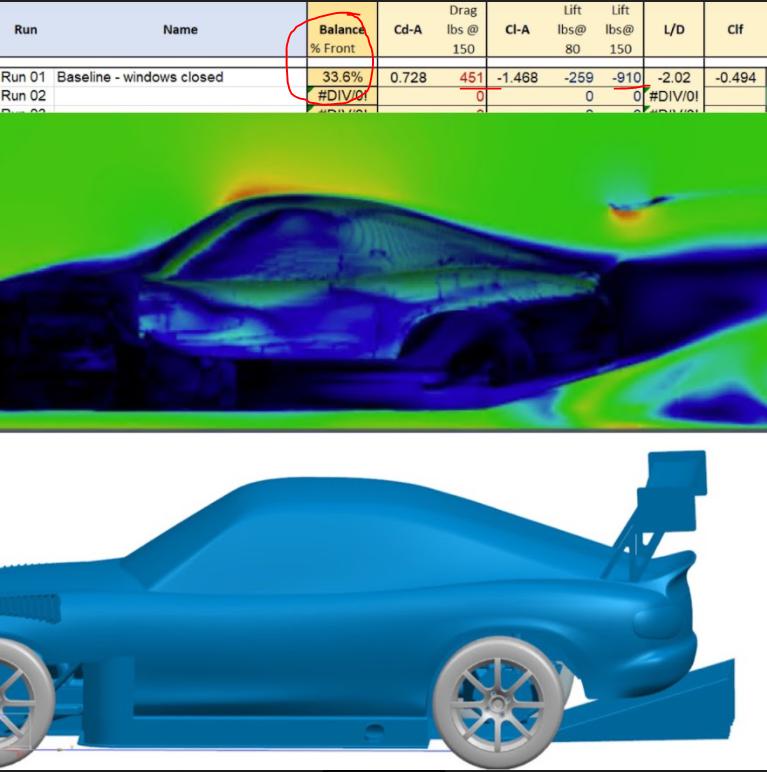
Tada!! the first run. Lots of work for the first pay off. The big red circle is the money maker. If you don't have balance then you don't have a fast race car. that's the part you need to pay attention to. 910 is a good number for downforce. very good infact but 33% front nose weight ... isn't but wait it gets worse.
we added the front some ducting that didn't show up in the scan and the dual-element wing.

and it got WAYYYYY worse now down to 19.8% front balance. Looks like we should ditch the dual element kit and focus on front downforce.
that's it for now. as it comes along i'll update this thread, thanks for checking in.
Well presented. Like you, I can't talk about the projects I spend my time on, but you summed up the process nicely for those that think it might be as simple as just uploading some files and hitting the GO button.
Ok I am excited to see how you can change the balance in the front. Short of canards and venting somehow up through the hood I have no idea how you do it. Aero on the front of a car is a mystery to me. Also why do you model the engine if you are going to go full flat bottom. I thought that was the best way to go about things.
Following with much interest.

Rodan
Dork
2/9/21 11:51 a.m.
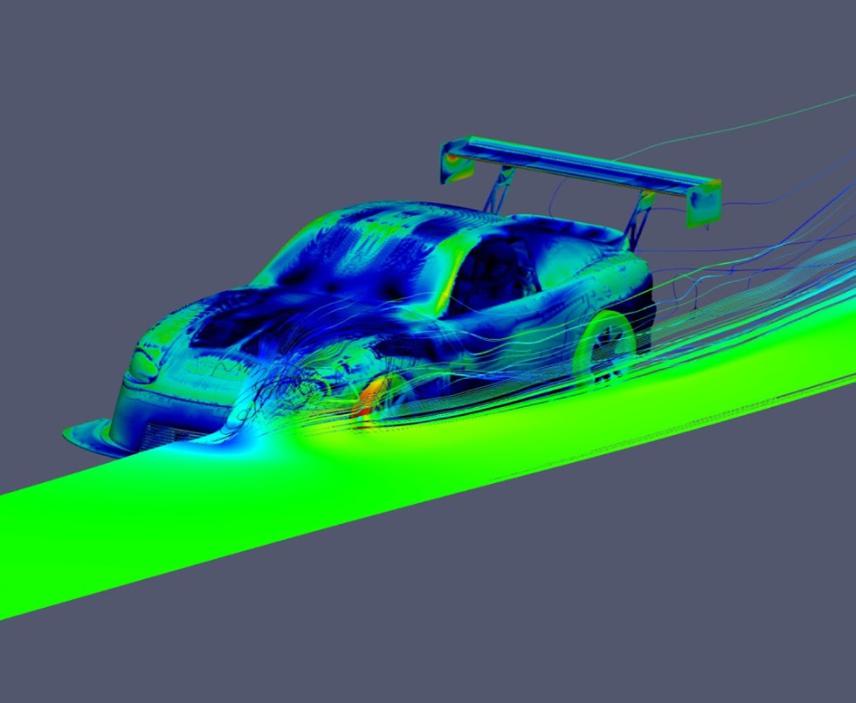
A dual element wing is going to take a LOT in the front to balance it... Here's what Emilio and Ryan tried:

I assume dark color is high pressure, right?
If that's the case, are the outlet vents on the hood and fenders dark because high pressure air is exiting the vent? or are they high pressure because of external forces and the air can't escape?
Maybe hard to tell the difference?
stafford1500 said:
Well presented. Like you, I can't talk about the projects I spend my time on, but you summed up the process nicely for those that think it might be as simple as just uploading some files and hitting the GO button.
"But I found this great file on Thingverse..."

Keith Tanner said:
stafford1500 said:
Well presented. Like you, I can't talk about the projects I spend my time on, but you summed up the process nicely for those that think it might be as simple as just uploading some files and hitting the GO button.
"But I found this great file on Thingverse..."
I am no stranger to finding a 3D model on the net and then spending some quality time with it in CAD to make it into useable solid bodies. Starting from point cloud data is another level of pain for generating a good CFD model. Water-tight is the jargon used frequently. Basically any small hole into a zone that does not commonly see airflow will wreak havoc on the computation. You wind up with huge numbers of cells that should not exist, usually in really tight spaces that drive the cell count even higher.
The cluster Johnny has posted pictures of in the past is probably working 24-7 to try and keep up with customer requests. Just having the idea does not mean hit the GO button, there is design time to update the parts/model, run the new model, and the time required to verify the correlation. There was also no mention of the method being used for the cases; there are a few and they get complicated quick.
For the record, most of my time is empirical testing, which gives global results very quickly (minutes Vs hours for CFD), but the prep side means making real parts (usually CAD is involved in that too, so the CFD can duplicate the effort). CFD will give more detail about any location within the model AND the global results you get from empirical. So, empirical can point you in the right direction 99% of the time and CFD can help you understand the minute details of the result. That SHOULD give you better understanding of the phenomena and direct further development.

BA5
Reader
2/18/21 5:28 p.m.
Did you find that your CFD result correlated with what you're feeling in the car? You say the 19% balance is bad, but are you hating the way it drives? Is it pretty under-steer-y?
Hey I didn't know you were on here. lol.

Shaun
Dork
3/9/21 9:02 p.m.
stafford1500 said:
Keith Tanner said:
stafford1500 said:
Well presented. Like you, I can't talk about the projects I spend my time on, but you summed up the process nicely for those that think it might be as simple as just uploading some files and hitting the GO button.
"But I found this great file on Thingverse..."
I am no stranger to finding a 3D model on the net and then spending some quality time with it in CAD to make it into useable solid bodies. Starting from point cloud data is another level of pain for generating a good CFD model. Water-tight is the jargon used frequently. Basically any small hole into a zone that does not commonly see airflow will wreak havoc on the computation. You wind up with huge numbers of cells that should not exist, usually in really tight spaces that drive the cell count even higher.
The cluster Johnny has posted pictures of in the past is probably working 24-7 to try and keep up with customer requests. Just having the idea does not mean hit the GO button, there is design time to update the parts/model, run the new model, and the time required to verify the correlation. There was also no mention of the method being used for the cases; there are a few and they get complicated quick.
For the record, most of my time is empirical testing, which gives global results very quickly (minutes Vs hours for CFD), but the prep side means making real parts (usually CAD is involved in that too, so the CFD can duplicate the effort). CFD will give more detail about any location within the model AND the global results you get from empirical. So, empirical can point you in the right direction 99% of the time and CFD can help you understand the minute details of the result. That SHOULD give you better understanding of the phenomena and direct further development.
That is exactly how thermal management and fan design projects I have worked on have panned out in industrial and consumer product engineering environments. 'Givens' keep popping up in the empirical prototyping and associated data gathering work that eventually blow up and then help inform the CFD parameters so that eventually the CFD becomes a useful tool for the particular architecture and environment. Airflow is fabulously complicated and even with very powerful computational tools it is human observation and imagination that ends up informing the tools. For awhile anyaway...
The fender vents are flipped around so they're acting as scoops? Did I understand that right?
Have you looked at dive planes at all? I found them useful to plant the nose on my car. A bit of a blunt instrument but it worked. I already had wheel wickers in place, glad to see that was actually doing something.
In reply to Keith Tanner :
I don't have a good picture see if I can explain it.
they are intended to have the widest part of the vent as the leading edge. that didn't fit on the fender so I flipped them and used the narrowest part as the leading edge and the widest part as the trailing.
the fins were bent as you normally would.


My first reaction to the front wing result was:
"I guess it might also shed some light another reason that encouraged Wainfan to put the front wing "way up high and clear" on that Scion TC time attack car."
Then I dug into the data a bit, and found that there's an interesting tidbit buried in it...

that the Front Wing setup seemed to make around 20% downforce at 80 than it did at 150, which is the only setup that responded that way.
it's probably a pretty limited area of rules and venue that align to be able to take advantage of that... and still get the balance you'd want out of the rear. but, I thought I'd point it out, in case anyone here can make use of it.
In reply to sleepyhead the buffalo :
i didn't run the CFD so I can only guess but I would assume the high-pressure area from the splitter grew at the higher speed and started snuffing out the nose wings performance.


