


In reply to JoeTR6 :where did you buy the radiator?

In reply to JoeTR6 :where did you buy the radiator?

In reply to frenchyd :
British Parts NW. It was on sale, and was actually $263. They no longer list it, which may be a bad sign. If it doesn't work out, I can always get a Wizard Cooling or custom radiator.
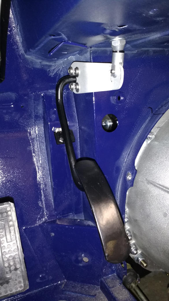
Back to work after a few days away to visit family. The new throttle linkage fits, but it's somewhat close to the header. I had to flip the bellcrank over and move everything to the outside. The plan is to mount a heat shield to the bottom of the intake that will extend down around the header. It can be supported lower down by bolting though this structure using some standoffs.
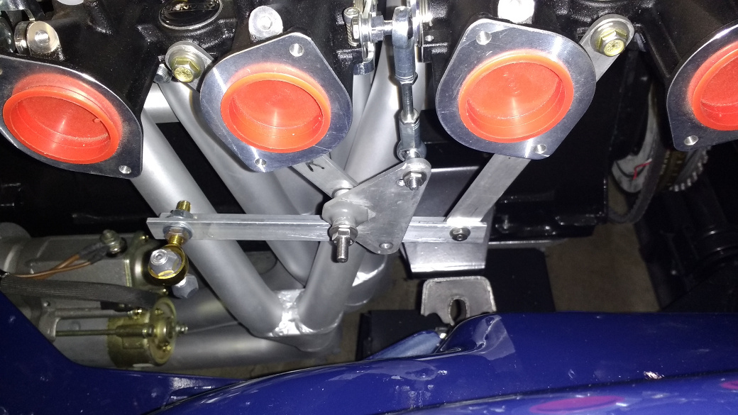
Now for the bad news. I powdercoated the stock throttle pedal and fitted it. There was a little problem with the stock location of the lever. It's black and hard to see, but is in the middle here.
If I cut 1/4" off the lever, it would clear the intake. But this doesn't allow for the engine torquing over. There's just not enough clearance to make this work. It's a consequence of moving the engine back 3/8". So moving on, here's the next alternative.
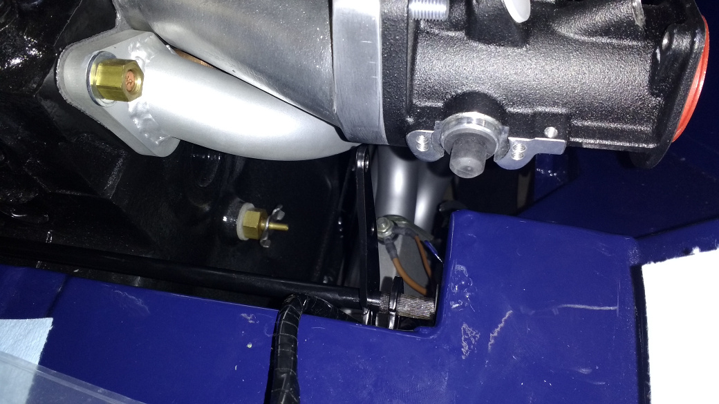
I'll need to drill another hole in the body. The lever is right on the edge of the steering column indentation, so I'll need to either bend it or bolt an extension to the side of the lever. The cable routing can go behind the engine and angle forward into the throttle linkage. In some ways, this is better than having the lever behind the intake. The cable was going to be really short to the point where I'd need to hard mount the ends to achieve the necessary bends.
After much blowing and raking of leaves, I managed to do a little bit on the TR6 this weekend. Rather than use the stock accelerator lever inside the car I'm making one. I made a disk that will be welded to the shaft and is drilled/tapped. The lever will bolt to this, allowing it to be adjusted and replaced. The stock lever is needed on the other side (after trimming off the end) to hold the shaft in place and act as a lever for the throttle return spring.
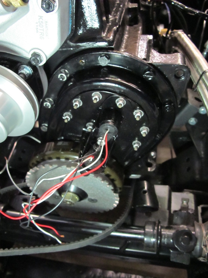
The brake and clutch circuits are now complete, but are still dry. The water pump and housing were also installed. Before I get too much stuff around the front of the engine, I need to set up the cam sensor. I pulled the access panel from in front of the cam gear, and it appears there is enough clearance to fit the sensor there. The button screws for the adjustable cam gear might come a bit close to the sensor, but could be used to hold down a washer with a small tab welded to it. Actually, I should put one on the other side but with the tab laid down to maintain balance. A tube welded to the access panel and an o-ring around the sensor should seal things up, and I can shim under the sensor for gap adjustment.
I have a plan and the parts to mount the camshaft sensor, but have been a little busy on my daily driver turned project car. Since I bought a Fiesta ST about 2 months ago, I've barely driven the MSM, and for good reason. It was barely drivable. Substantial oil leaks, timing belt noise (too tight), weak brakes, and a rear end judder that just kept getting worse. There was also a groan coming from the front suspension. Two weeks ago I pulled it into the garage and began taking things apart at both ends. The plan was to replace the diff mounts and fix the oil leaks. I ended up putting speedi sleeves on the crank nose and one camshaft, and replaced the timing belt (oil got on it). The power steering pressure hose looked suspect, so I replaced most of the power steering hoses.
At the rear, I dropped the diff to put in new Mazdaspeed mounts. Those things are a booger to remove, especially after 125k miles. The driveshaft was toast, so that got replaced. I also decided that while the rear end was torn apart to try polyurethane bushings. Oh, and the brakes were down to the last 1mm of pad. Of course, three of the bolts holding the ABS sensors to the rear uprights broke, so those had to be drilled out.
The front suspension noise turned out to be an adjuster with the washer turned 90 degrees. The tabs that are supposed to hold it in place sheered off. So a new set of adjusters are going on too. When I get this aligned, it's going to be a more aggressive autocross alignment. Because race car.
So yeah, not much got done on the TR6.
Still going on the MSM. I finished the engine and rear suspension work, so filled the fluids and took it for a spin. It felt pretty good, if a little tail happy. New poly bushings in the rear with 125k original rubber in the front will do that. So I pulled the front suspension off to do the bushings and brakes. One of the lower ball joint boots was torn, and the upper ball joints were pretty loose. Time for new upper A-arms. Parts took a while to get here, but the driver's side is back together.
I should have started another build thread for this. It's going on three weeks of all weekend and every night after work time. I'm really curious just how much better the Miata will feel now. There's a strong temptation to mount up some Hoosiers and try SCCA BSP next year. It's time to find a tire trailer.

Kinda glad to hear you arent giving up on the MSM. My first miata drive (not race) ever was in one and I was smitten.
Offer may be a bit late, but let me know if you want to come down and use my lift in the heated garage. With me being laid up I am pretty much always home. Only catch would be climbing in the mustang for me and backing it out and pushing the spit off the lift (I have a snowblower with tank treads that moves it like a charm) and returning stuff when you are done. You have my number on the CDC site.
In reply to Apexcarver :
Thanks, but I'm almost done (hopefully) and can't drive the car until it's done anyway. Plus, I'm kinda starting to like the feel of cold concrete on my body. It keeps the swelling down. Since we put in an insulated garage door a few years ago, I can keep the space reasonably warm with a space heater.
The Miata is done and seems to drive fine. Very fine, actually. The poly bushings aren't as punishing as I expected. Major bumps are definitely harsher, but not painfully so. It still needs an alignment and I'd like to corner weight it this time. The only thing left is a slight retune of the Megasquirt. Someone else noticed that I had the injector dead time set to the 3 bar value, but the MSM runs at 4 bar. The change to dead time wasn't large, but it seems to have affected the VE table by about 10-15%.
So, back to the TR6.
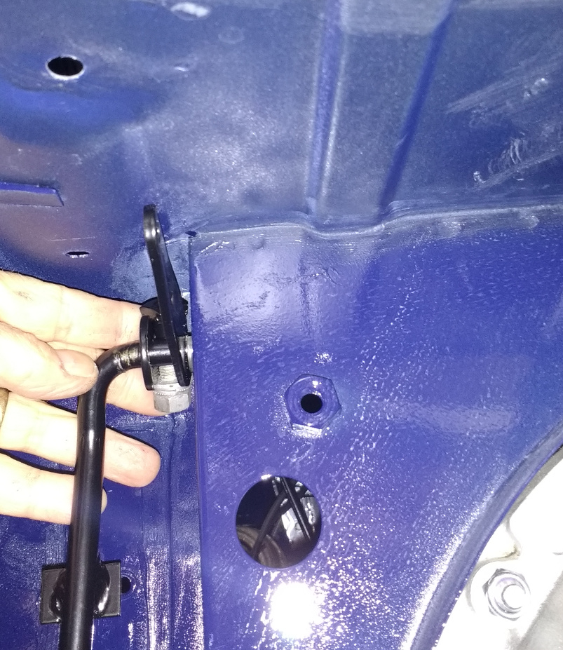
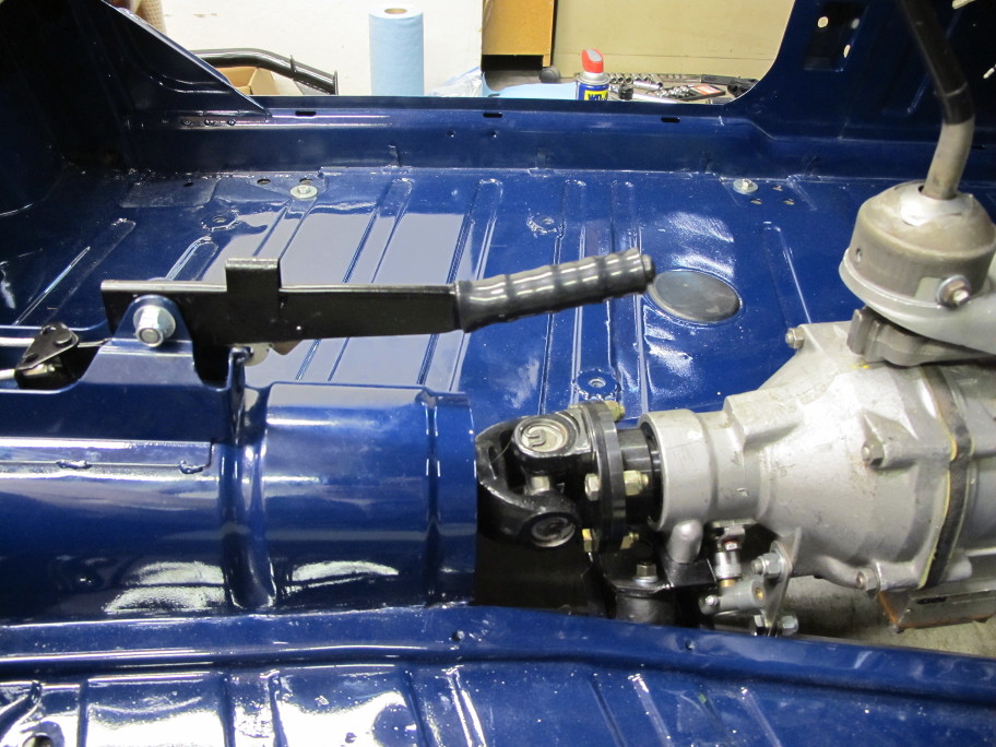
Finally, the throttle cable is done. I'm routing the cable over where the battery will go.
Here's the new pedal setup. I slotted the holes in the lever so that the pedal height can be adjusted. The pedal throw is perfect. With a bolt and jam nut threaded all the way into the throttle stop on the firewall, the throttles just fully open.
Moving on, the next thing to finish is the cam position sensor.
If I weld a tooth onto a washer and put it under the missing allen bolt, the cam position sensor could then be mounted on the cover. The tooth would sweep past the sensor about 30 crank degrees before TDC.

In reply to JoeTR6 :
I like your access panel, I have to do the same for my Spitfire, which uses the same timing chain cover, and was trying to decide the best way.
Are you using this Ford cam sensor?:
I plan to do a similar deal with a tooth on the sprocket, and will braze a steel tube into the cover at a slight angle for mounting the sensor.
The sensor already has an O-ring to seal, but may have to ream the tube ID to size.
A tab brazed/welded to the outside of the tube so the sensor can bolt on, with washer/shims to fine adjust the sensor gap to the tooth.
I'm using the fixed hall-effect sensor that diyautotune sells.
https://www.diyautotune.com/product/hall-effect-crankshaft-position-sensor/
It's worked very well on another TR6, and I'm already using one for the crank sensor.
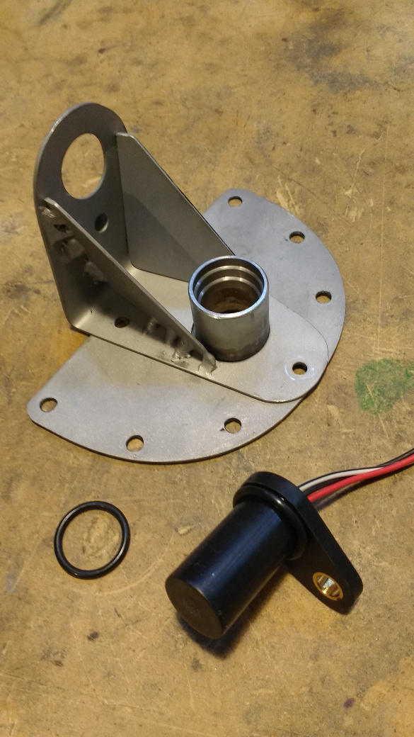
I'm going to use a steel spacer and turn a groove on the outer end to hold an o-ring. The crank sensor bracket goes over the cover, so I may just tack the two together, weld on the tube, and add a tab for the sensor mount.
If I wasn't already using the fuel pump mount as a place to drain a catch can, I'd probably just mount a threaded sensor there and use the fuel pump cam as the tab.
In reply to JoeTR6 :
Yes, I had considered using the fuel pump lobe as well, but had concerns based on a job I had working on mag tachometer circuits.
The pump lobe is a circular eccentric, but magnetic pickup sensor circuitry works better with a 'tooth' or slot.
Signal voltage varies with RPM, and a square edge yields a signal with a fast risetime/falltime that gives stable timing.
I could grind away on the pump lobe, but that's a one way modification I didn't want to do.
That diyautotune Hall effect sensor looks pretty good, I may try one out, chuck a cam into the lathe and see how well it works sensing the pump lobe.
I made the washers with tabs (one for each side to balance), but there's a slight clearance issue. The tabs were ground down to 0.25", which is about as low as I wanted to go. Otherwise, they would be level with the bolt heads. One of my welds on the back of the timing cover wasn't ground down all the way, so it looks like that has to come off. Oh well. I also welded the tube onto the cover plate, but forgot to turn the o-ring groove on the lathe first. It's a little harder now, but I'm hoping a step drill will be a close enough size.
The cam sensor mount is almost done. I just need to weld a tab with a nut somewhere to hold the sensor in place. With the sensor all the way in and the larger o-ring acting as a spacer, the sensor should just touch the trigger tooth. The other o-ring will seal it up.
I tried to remove the timing cover today but couldn't remove the crank pulley bolt. The tires were just spinning on the floor (they were old and hard 25 years ago). I'll try putting in the emergency brake cables and spark plugs. If need be, I can hold the gearbox flange with a tool. I'm only about 20 mils short of clearing the cover, so it should be easy to remove the high spots for that once it's off. I may use a thicker gasket on the timing cover for some extra clearance. This will also move the oil seal enough to avoid the slight groove worn on the crankshaft nose sleeve.
Nothing is as easy as it should be.
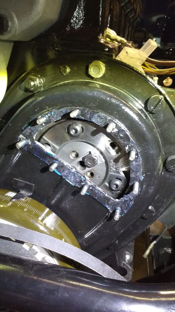
To remove the timing cover, I also had to unbolt the steering rack and remove the crank pulley and damper. Just getting the pulley bolt loose took some effort. The car came with extensions for the parking brake levers, so those helped hold the rear wheels enough to break the crank bolt loose. Then the damper wouldn't budge. A three-arm puller wouldn't clear the trigger wheel, which would bend if I pulled on that. The countersunk allen bolts holding the trigger wheel were set with blue loctite, so I broke an allen socket. An allen key and pipe got those loose. The damper came off once the puller could grab it; some rust had developed on the crank nose. It is British, after all. Finally the cover came off. Looking at the backside of the cover, it appears that the bolt head with the washer as well as the tab scraped across the indentations on the timing cover. The protruding welds were ground down.
OK, so there's not much clearance here. Just adding a washer under the bolt heads makes them contact the stock timing cover. The only way to save this was to weld the tab directly to the cam gear hub like so.
I removed the gear to keep it clean. Of course, one of the allen button screws holding the gear on the hub stripped, so I had to cut the head to relieve the tension on it.
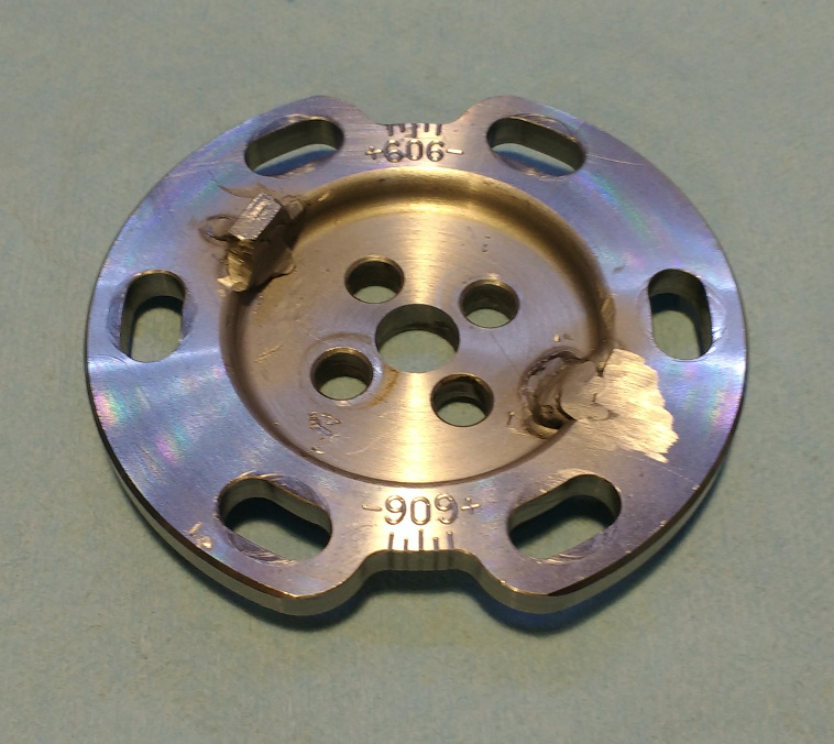
My current concern is how sensitive is this gear to balance? I put a blob of weld on the opposite side, but should I have the hub properly balanced? A model aircraft prop balancer is only $20 and may get this close enough. Or I could DIY a simple static balancer using a 1/2" shaft through the center.
I think I have a "good enough" solution for the cam gear hub balancing. Why spend money when you can throw together scrap from around the shop?
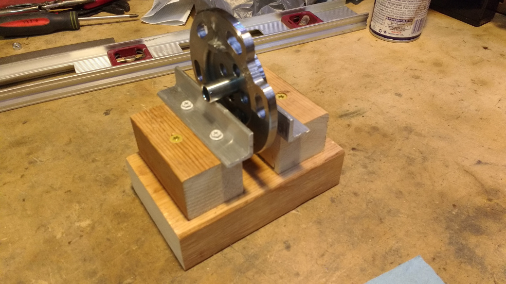
Some careful cutting, sanding, and filing turned out a static balancer that is fairly true. The center bore is 0.499", so a 1/2" OD spacer fit well as a spindle. I even polished the ends of the spacer in a drill press with some 2000 grit paper. While this isn't perfect, it showed the side with the tab was definitely heavier. I started a countersunk hole with a drill bit and switched to a Dremel to slowly remove material until it appeared to not favor that side. This stand is sensitive enough that putting a store receipt under one side would cause the hub to roll to the other side. I spun the hub on a drill (to ~ 1500 RPMs) afterwards and felt no vibration. So good enough, I think.
In other news, I picked up the doors from the paint guy and dropped off all four fenders. So maybe 2-4 weeks before I have all of the panels ready to hang.
It was a long weekend of working on the car, but the timing cover still isn't back on. All of the parts are ready to go, I just ran out of time. It turns out some idiot welded the tooth on the wrong place on the cam gear hub, so I had to turn the hub 90 degrees and re-time the cam. I decided to advance the cam 3 degrees as a starting point. Everything was fitted up, including a dry gasket, so that the cam sensor depth could be checked. Pushing the sensor all the way in leaves 0.002" of clearance. That works out well as I can set the sensor gap with a feeler gauge
What took way too long was bead blasting the timing cover. It got knicked up from too much wrenching, so I thought it wouldn't take much effort to powder coat. Wrong. That POR15 engine paint is tough stuff. It stuck better on the cast block, but still didn't want to strip quickly, even with aggressive media.
The timing cover is back on along with all of the stuff on the crank. I tested both crank and cam sensors with a battery and voltmeter.
The handbrake lever was cleaned up and powder coated.
I still need to reattach the steering rack and crossmember tube. For the steering rack, I'm using some poly bushings that I've had for a while. The stock rubber ones are difficult enough to compress sideways so that they aren't loose. These are worse. I'm working on a tool that goes between the mounts and presses outward.
One annoyance of this setup is that the alternator/water pump belt cannot be changed without moving the steering rack and crossmember tube. But that can be an issue on a completely stock TR6.
I took today off to work on the car and take a break from my job.
Today's task was to finish the steering rack tool. It took some adjusting of the original design, but it turned out well.
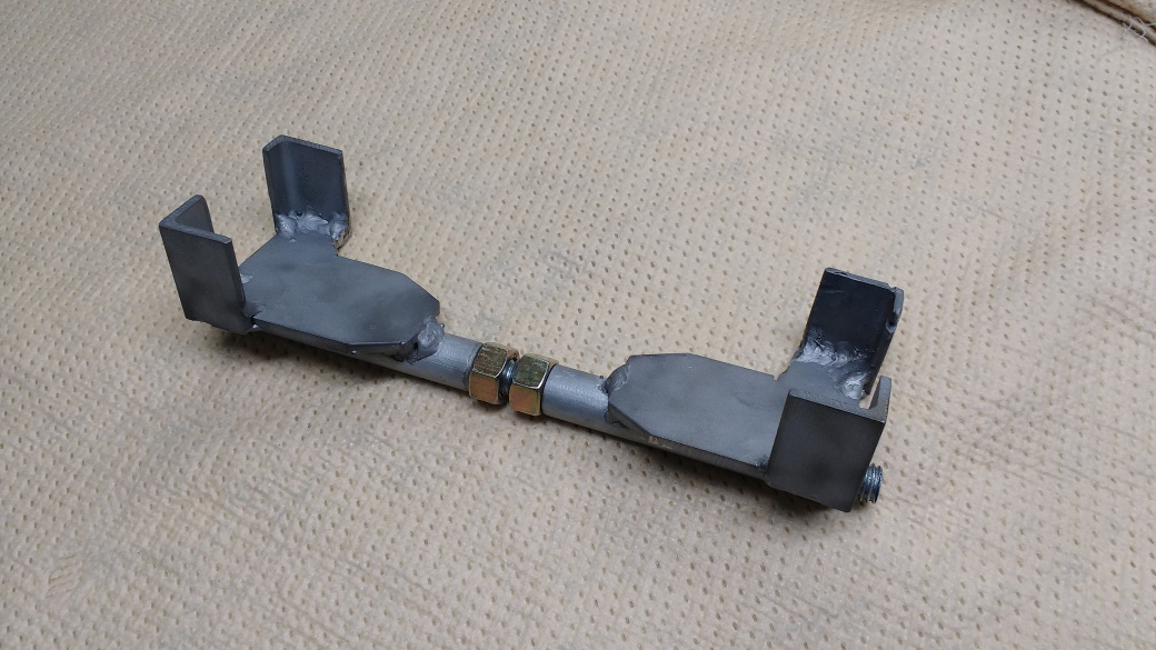
Here's how it looks in action.
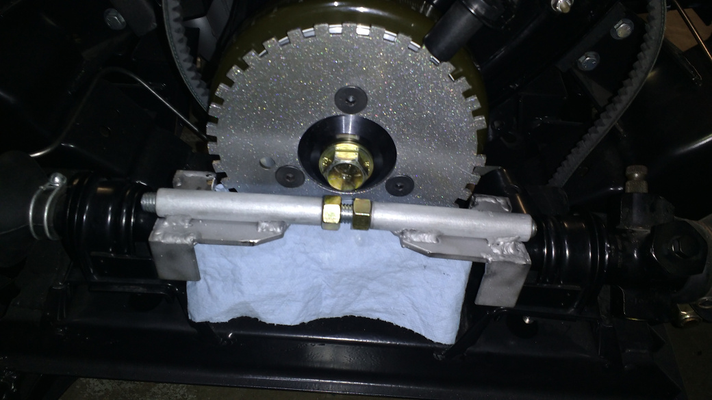
In the past, I've used a combination of c-clamps to compress the steering rack bushings. This worked so much better. I had to offset the jackscrew somewhat to clear the crank bolt and notch the brackets to clear the trigger wheel. So with that finished, the steering rack and crossmember tube are back in. Next is the exhaust heat shield.
More stuff went in, but now some of it needs to come back out.
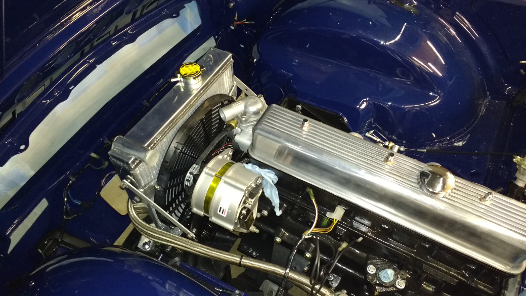
The good news is I found the alternator that had been hiding under a box. While looking for the radiator stays, I found the bumper mounts that had been powder coated over 20 year ago, so those went on. The radiator went in next. When I tried to fit the alternator, the belt wouldn't reach over the pulley. I cut a notch in the front engine plate to clearance a boss on the alternator and just barely got the belt on. It could stand to be another 2-3 inches longer as it's crowding the #1 spark plug. Unfortunately, the radiator, steering rack, and crossmember tube all need to come back out to replace the belt. No big deal. Finally, the right combination of spacers and washers were found to make the Fiesta alternator line up with the modified position of the crank and water pump pulleys.
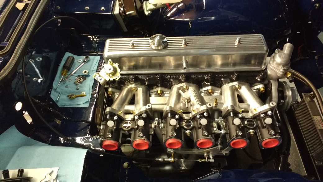
I pulled the intake to play around with the exhaust heat shield and get a template of the throttle outer flanges for making an air box.

That blue really jumps out, love it! Can't wait to hear what this sounds like with the ITB's. Will you get it dyno'ed once it is up and running? Will be very curious what kind of power it will put out with a modern fuel injection system, since the ancient Lucas Mechanical Injection in the UK market cars can d0 150 HP stock.
In reply to dherr :
I'll get this dyno'ed at some point after it's been run in and sorted. I'm hoping for 130-140 at the wheels, but maybe less. This car has a milder cam and no roller rockers that the TR6 I co-drive has. That car is fully bonkers with fiberglass for almost every exterior panel and no interior. Come by a CDC autocross in Frederick some time, and bring the Spitfire.
I think the blue looks a little lighter and more purple in pictures than in real life. The last picture is pretty close, though.
Great, can't wait to see it in action. I will definitely get involved in the CDC autocross here in Frederick, been on my radar for a while now and will definitely bring the Spitfire.
Yesterday was 10 hours of putting new ball joints and LCA bushings on my wife's MINI. It wasn't a hard job, but there was just a lot to remove. Once I figured out that it's better just to remove stuff than work around it, things went smoothly. For example, the entire exhaust came off by removing a single clamp, 4 rubber hangers, and a small tunnel brace.
Today I made some headway on the TR6. The new alternator belt is 1.5" longer than stock, and this put the alternator in the right place. I couldn't find the stock tensioner bracket, but should probably make something that doesn't require a wooden hammer handle as a lever to set the tension.
With a good belt in place, stuff went back in. The coil pack went on the wheel arch under the brake master cylinder. There's a factory indentation that is the perfect size for it. A bunch of brackets were powder coated, including the radiator stays. I'm still looking for silver powder coat that doesn't look like glitter.
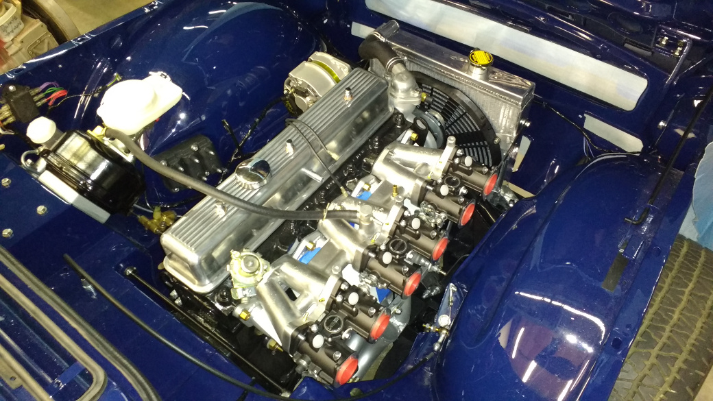
The last thing was messing around with the heat shield between the intake and exhaust. There's a piece of paper cut to a reasonable shape taped into position above. I originally wanted to run it most of the way to the flanges, but there's just not much room between the two (maybe 1/8"). If the shape is just right, it may work. Or it might rattle like crazy. The main thing is to keep radiated heat away from the throttles and fuel rail, so I'll shorten the template somewhat.
You'll need to log in to post.


