


Those fasteners give the car a nice Mad Max vibe. ![]() Good progress, can't wait to see it in action.
Good progress, can't wait to see it in action.

Those fasteners give the car a nice Mad Max vibe. ![]() Good progress, can't wait to see it in action.
Good progress, can't wait to see it in action.

Kinda like a collar for a Pit Bull....

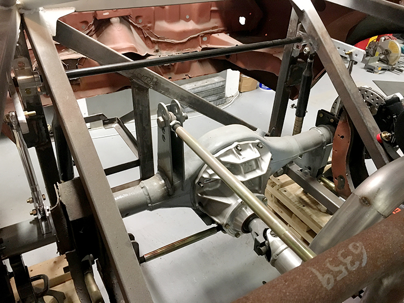
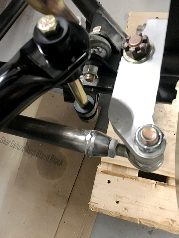
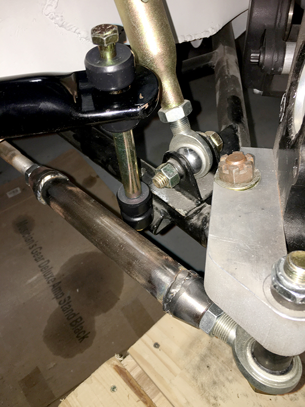
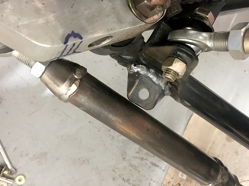
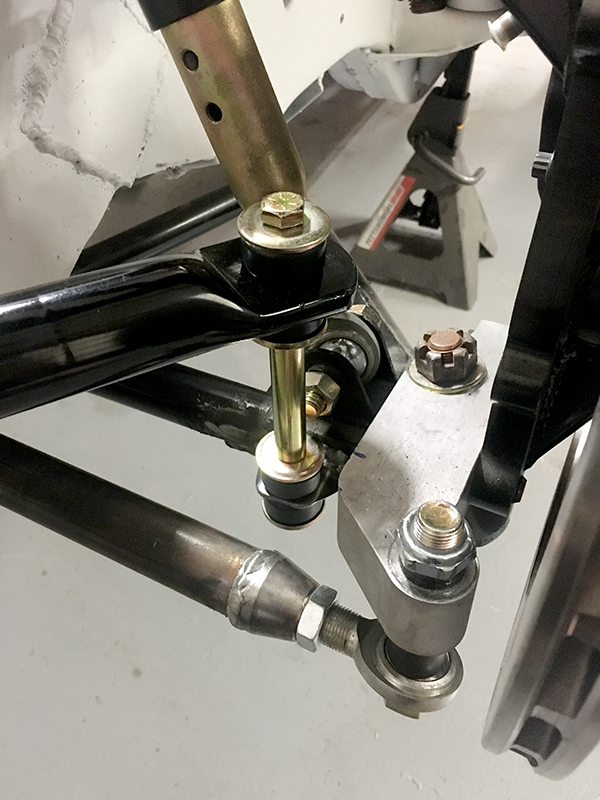
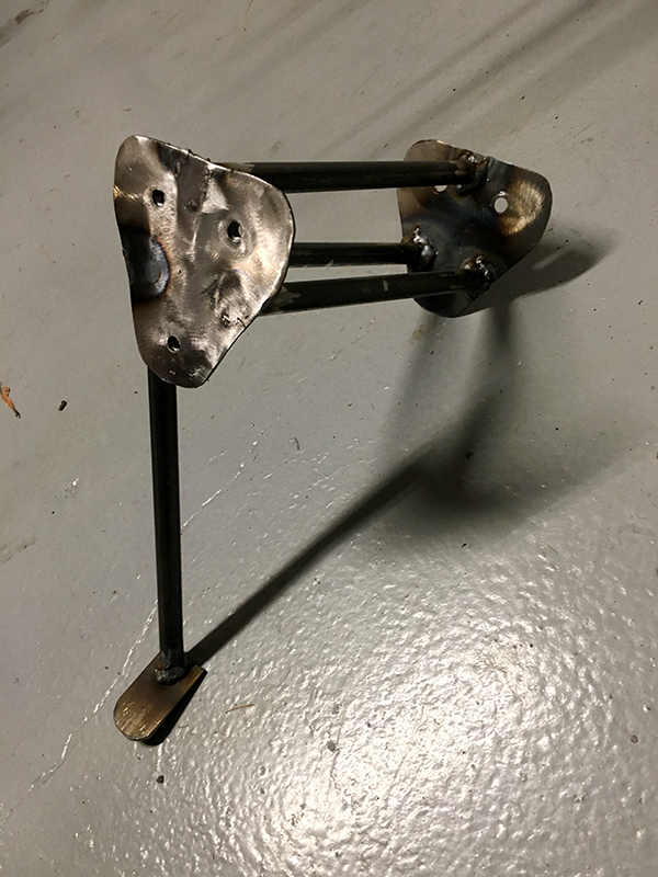
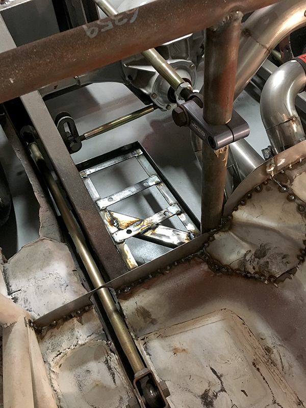
Another small one here, but I got the axle side brackets for the rear sway bar built. They still need to be welded to the axle, but they are fleshed out and the concept works. The holes in the bracket correspond with the ones in the sway bar arms, so I can adjust the stiffness of the bar while keeping the end links vertical.
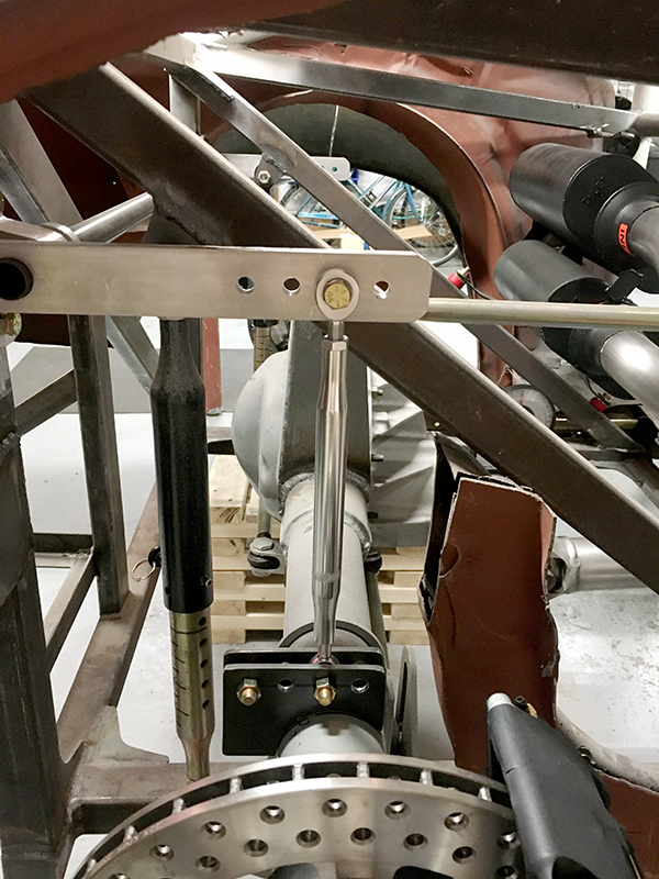
There used to be so much room back here. Things are filling up fast.

On the rear sway bar (and fronts too), if you find you need some assymetry, runnning the drop links at steeper/shallower angles than 90 degrees can some progressive/digressive bar action into the mix.
stafford1500 said:On the rear sway bar (and fronts too), if you find you need some assymetry, runnning the drop links at steeper/shallower angles than 90 degrees can some progressive/digressive bar action into the mix.
In theory, I think I could run offset holes and get that same sort of effect. Thoughts?
In reply to Gimp :
Yes, but the angularity gives a more non-linear reaction.
Hoping around from section to section on the car in an attempt to get this thing into paint soon.
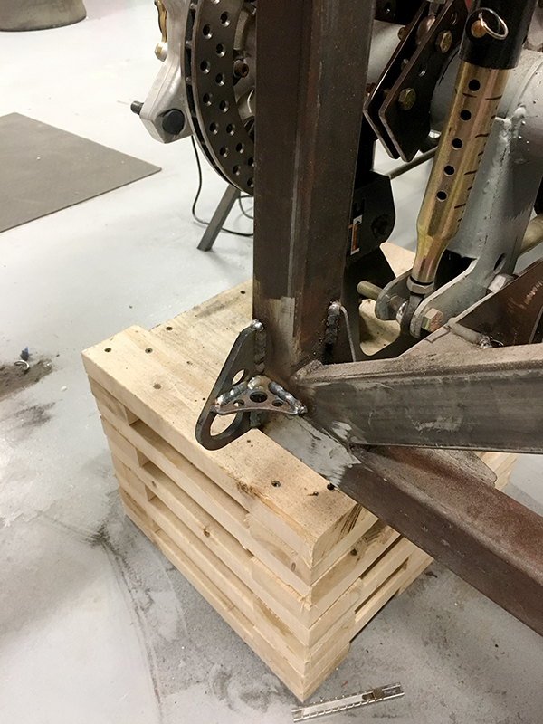
I picked up some tie-downs for the back of the car and got them in place.
Then I moved to the flanges and tabs for the rear firewall and trans tunnel.
![]()
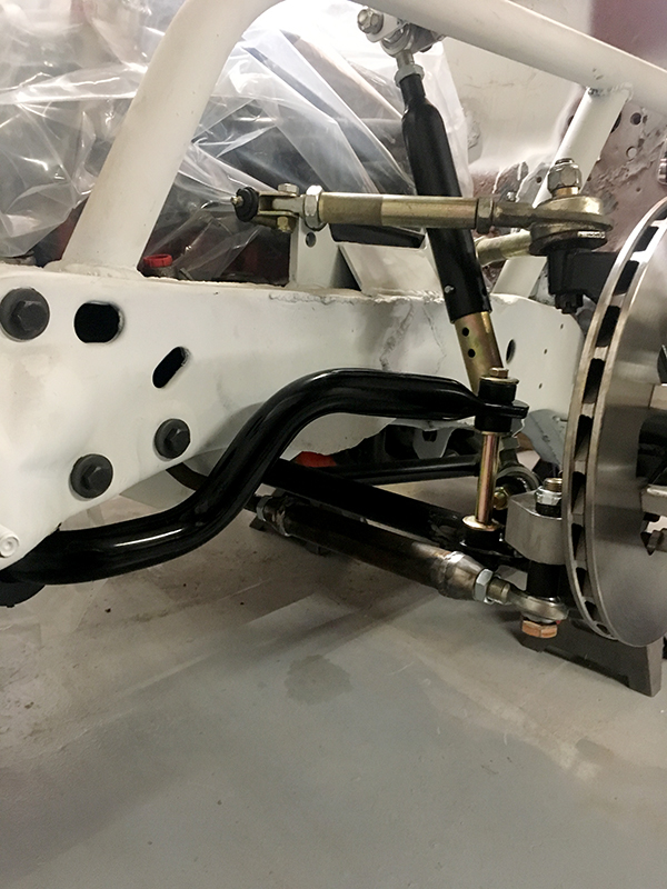
I also lucked out and my new custom steering arms from Coleman Racing arrived. They were happy to make up a set of arms to meet my specs. You can see the difference from their "stock" arms.
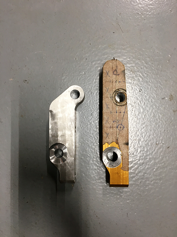
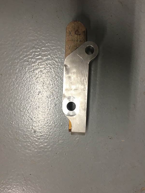
Some of the changes include the obvious relocation of the tie rod hole for increased Ackerman, and we thinned out the rear mounting area by a 1/4 inch. The rear bolt had been hitting the shock mount at full lock and limiting steering. Removing the 1/4 made a huge difference.
And here is everything installed.
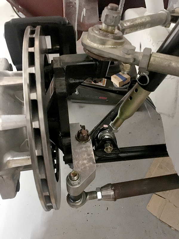
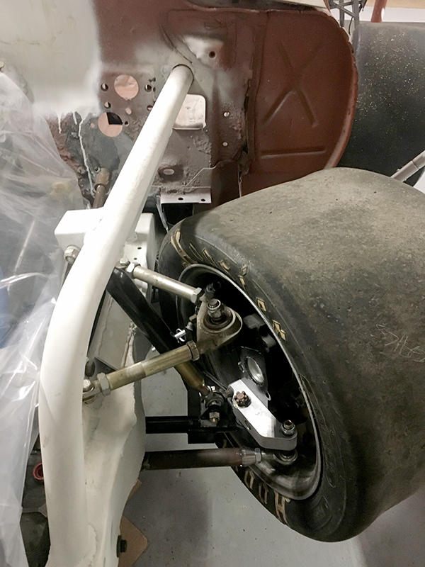
Hard to get a good picture in the garage, but there is definitely some Ackerman now.
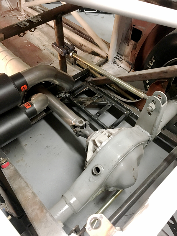
Your linkage under the nine inch is a version of a watts? Had you even considered some 'mumford links' when you fab'd this ? and now his reply will be what the berk is a mumford. ![]()

He has an underslung watts, at this point I would urge him to get it running before making revisions on that front. ![]()

Not a big fan.

In reply to Gimp :
I thought he was amazing

Got the rear sway bar axle side brackets tacked in last night. Nothing to really see there photo wise.
I then moved to the front to mount of the massive Detroit Speed Engineering sway bar. I originally wanted to use a splined style sway bar, and in the future I still might, but part of me wanted to keep the project moving with an "easy button." I picked the DSE bar because they are the only people I could find that actually published a rate (816lb/in).
Well, I went to mount it up and realized there is no "easy button" when it comes to a car like this.
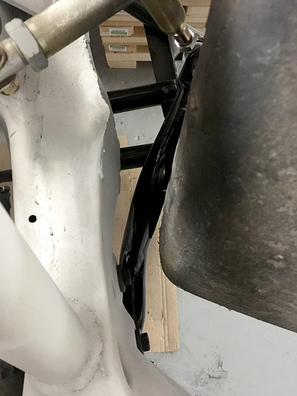
1. We cut off the passenger side sway bay tab, for some stupid reason.
2. The driver's side has some weird circle track sway bar mount.
3. The new steering arm will have to be clearanced a little to get full lock.
4. My front wheels need to be 6" backspacing, and not 7, to get full lock.
Lefthander (who I got the lower control arms from) sells the sway bar bracket I cut off, so I ordered up two and will weld them in when they arrive. I'll probably wait for one of my machinist friends to help me with the steering arms before I destroy them with an angle grinder. As far as the wheels, I needed to order up some new ones anyway.
Borrowing some scales this weekend and I'm going to "fully" assemble the car, minus things like fluid, lines, gauges, bodywork, etc. Basically the rolling chassis with suspension, motor, trans, rear, seats and steering. Any guesses as to the weight?
#2275
759NRNG said:#2275
I knew I was at a lot of posts in this thread, but I didn't think it was that many. ![]()

Gimp said:
Isn't this such a fun hobby?! I find ordering and reordering stuff over and over to be the best, most fun part of building a car!
Right up there with return processing!
As for weight, I'm gonna say 2750lbs.
I'm in for 2450...
For once a part was cut off that needed to be added back on and I wasnt involved in cutting it off in the first place! ![]()

1950 roller.
Crackers said:Gimp said:
Isn't this such a fun hobby?! I find ordering and reordering stuff over and over to be the best, most fun part of building a car!
Right up there with return processing!
As for weight, I'm gonna say 2750lbs.
I say less than that. My 81 Camaro was 2770 lbs in running and driving condition, before adding ballast to get to the weight minimum (3000 lbs). I would guess 2250 lbs.

2817 lbs
Update time!
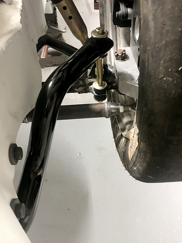
First off, I wrapped up the front sway bar, by adding the tabs to the contorl arms.
The good news is they do not hit the tie rod at full lock, by just a hair. The bad news is actually not that bad. I wasn't drawing a penis on the steering arm - that's simply the little bit that I need to clearance to get around the sway bar bushings for full lock. There is plenty of meat in the steering arm, so this shouldn't be an issue.
Now, for the bit I was most interested in. Weight.
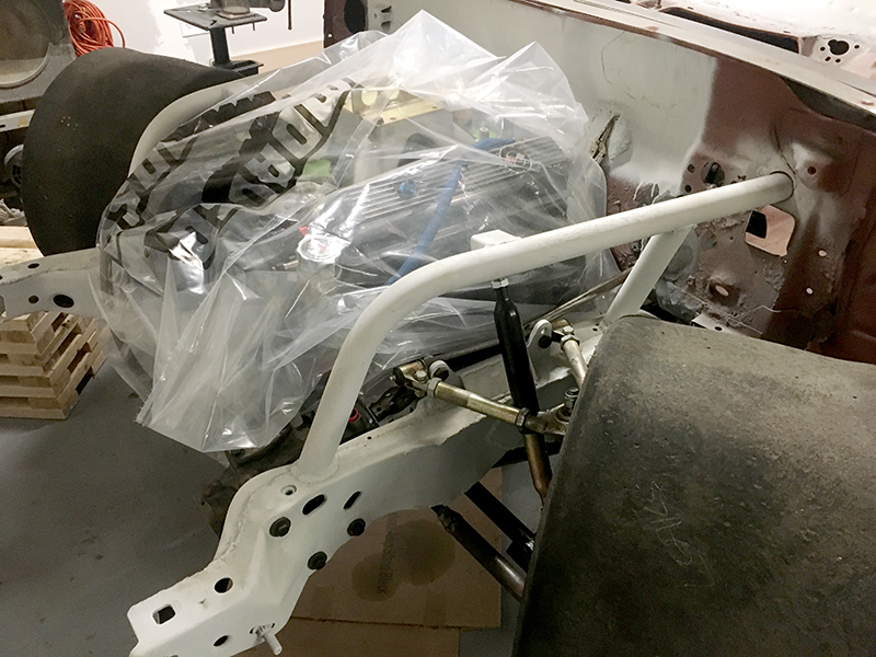
I installed the seats, core support, radiator, steering, and fuel cell in order to get an idea of where things stand. There are still plenty of bits to go on the car, but the idea here was to get a rough idea so I know where to build my ballast racks and so I'd have a good idea of how much ballast I need. Bodywork wise, there is no more sheet metal to go on the car. Everything (front clip, hood, deck lid, doors, etc) is fiberglass.
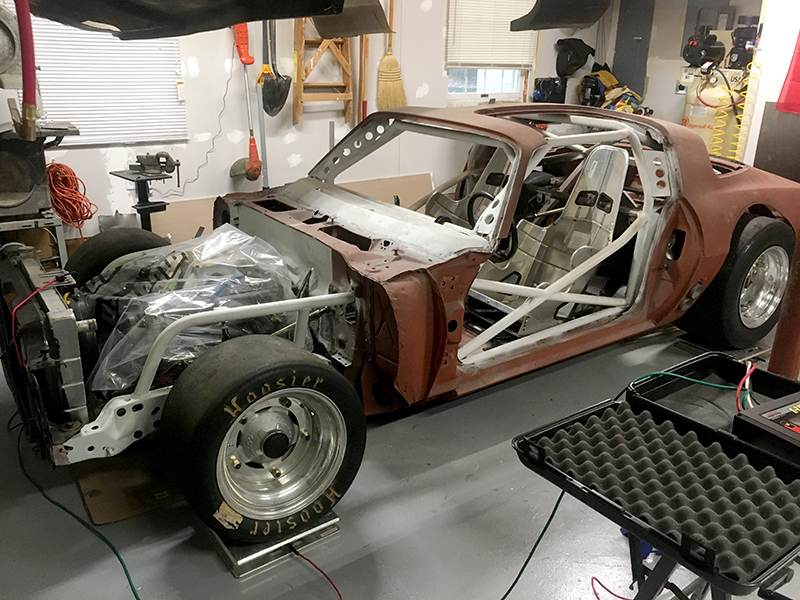
It's pretty rad seeing the car in this state - it's the most "car" it's been in years.
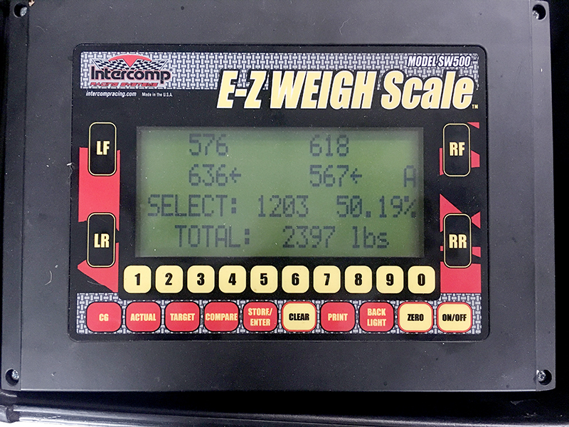
So, the moment I'm sure you've all been waiting for.
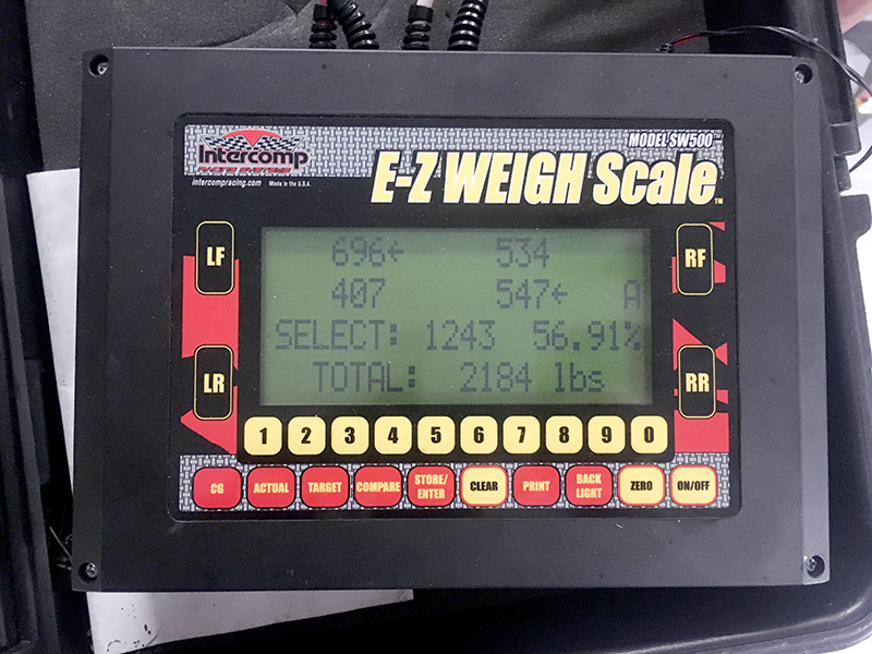
2184lbs. About where I expected the car to end up. That's over 800lbs short of the minimum weight, but as I mentioned, there is still a lot to go. I'm hoping that the finished car, before ballast, will end up at 2600lbs, and I think that's pretty realistic. The good news is the remaining 400lbs of weight get to go where I want it.
Dusterbd13 said:1950 roller.
Applying Price is Right rules, you're the winner, but you (thankfully) were 234lbs light.
Honorable mention goes to Randy with the 2250, only 66lbs off. That said, he had an edge considering the chassis and the motor.
Someone should probably take these scales away from me...
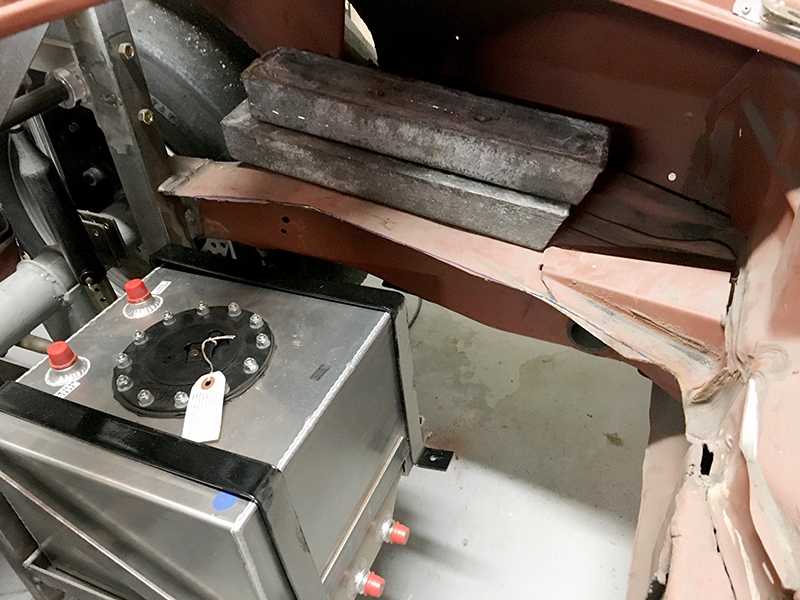
After looking at the un-ballasted rough weight distribution, I decided that I wouldn't put the battery behind the passenger seat. Instead I chose to mount it in the "trunk" and save that area behind the seat for a ballast rack.
After that was put in place, I just placed 200lbs of lead behind the rear tires. I will actually make a way to mount the ballast later, but this was to get an idea of how it shifts the weight.
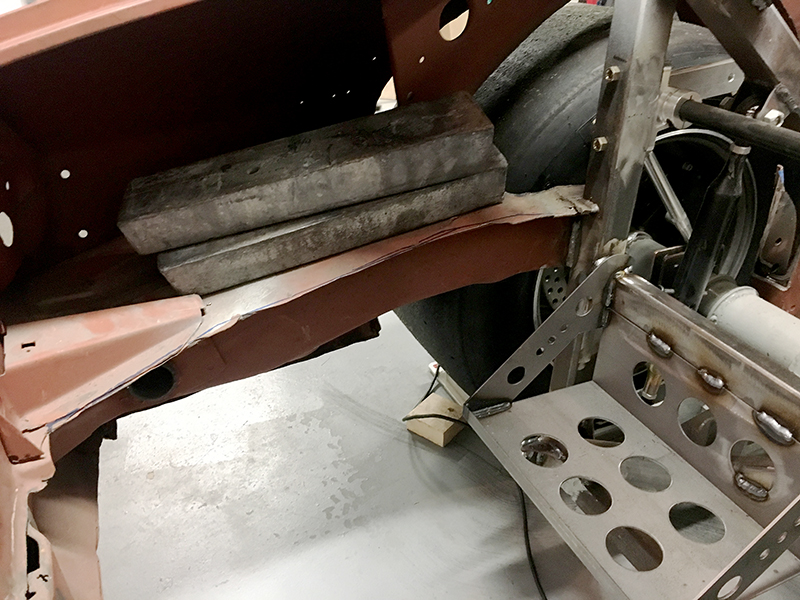
Pretty happy with how the balance is working out. Once the car is all said and done, I can't have more than 51% rear weight bias, so getting this close without a front clip, etc, and a lot more ballast to put in was a good start.
I'm taking a week off from work soon and using it to get the car over the current hump and a big step closer to being a runner. Stay tuned.
So I took the past week off, and one of the main goals was to knock out as much on the car as I could. I had a goal set, but my eyes were a bit bigger than my stomach. Despite that, I'm pretty happy with the progress made.
I started with the gas pedal. I have short legs, but I want to sit as far back in the car as possible. When Larry installed the brake and clutch pedals for me, I had him move to help enable this, but that left the stock gas pedal in the wrong place. Time to fix that.
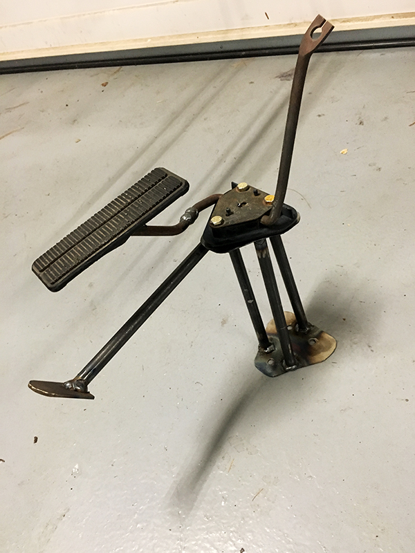
I made (and since the photo was taken, braced up) an extension that would still allow me to use the factory gas pedal (which is just something I wanted to do - I felt like the original "go pedal" just hand to stay).
This would bolt into the factory location (plus a new mounting point to stabilize it) and allow the gas pedal to land in the right spot. I angled it slightly to get the gas pedal tighter to the brake.
Bolting up the pedal to the extension made this happy little dancing robot (IMO):
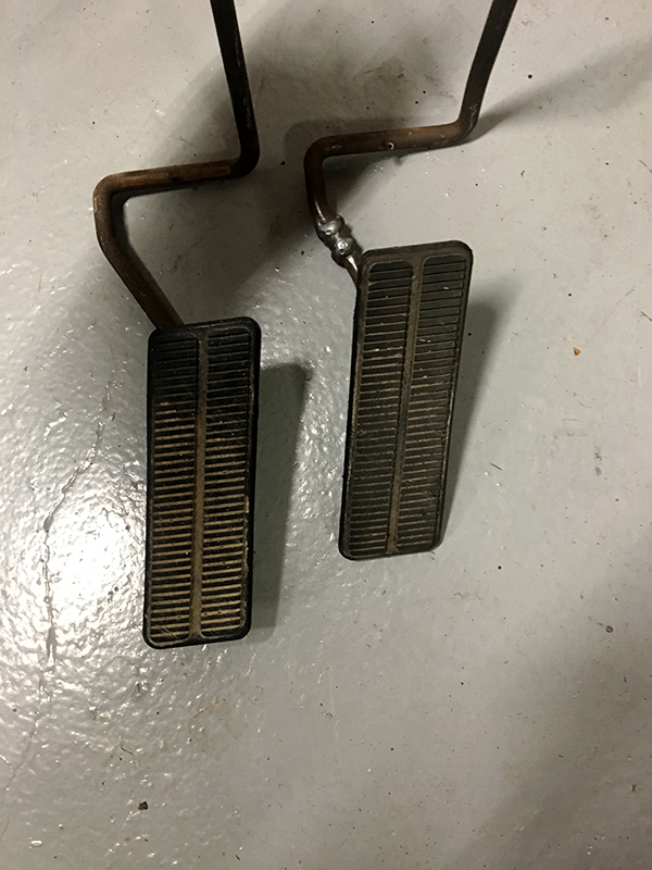
Keen eyed viewers will notice a weld on the gas pedal arm. When I first installed it, it still wasn't quite where I wanted it in relation to the brake pedal, so I removed about 1.5" from the straight section of the pedal, welded, and then sleeved it. Here it is next to a stock pedal:
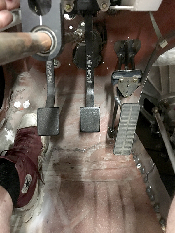
That gave me this for a final setup, and it worked out great.
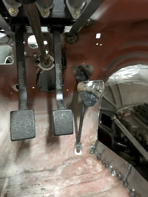
Next up, we stayed in the pedal theme, but this time it was the dead pedal. The stock setup doesn't have a dead pedal, with the e-brake and the high beam switch in that location. Since I won't have either, and since you don't need to use the clutch after 1st gear, a dead pedal was essential.
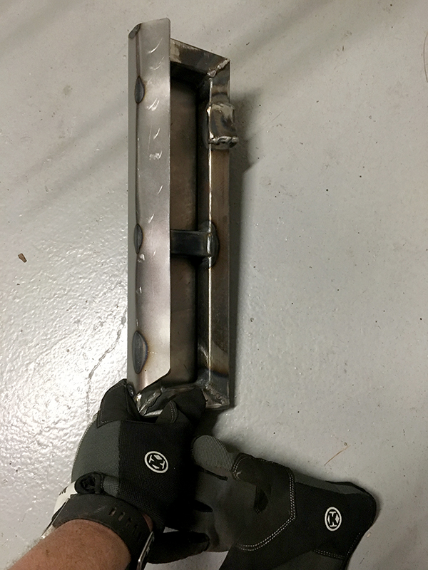
Luckily, due to the fact that this car needs to gain some weight fast, I could really overbuild this sucker. I anchored the pedal to the stock stud for the emergency brake, and then welded a flange into the floor for the bottom of the pedal to attach to. The frame was made out of 1x1 steel.
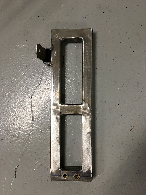
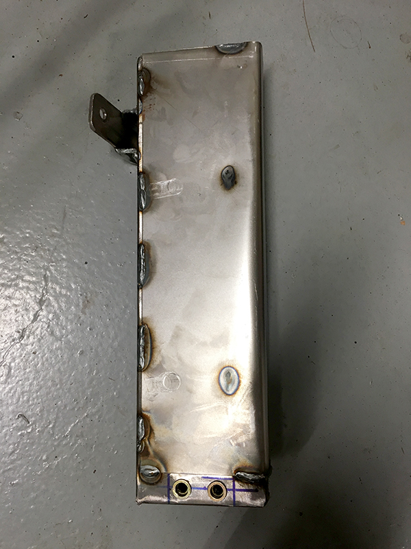
I then covered it with a piece of 16ga steel, and folded the backside over at an angle so your foot wouldn't get caught behind it when operating the clutch.
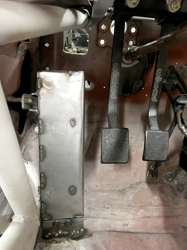
All bolted in:
And the picture of the new updated office:
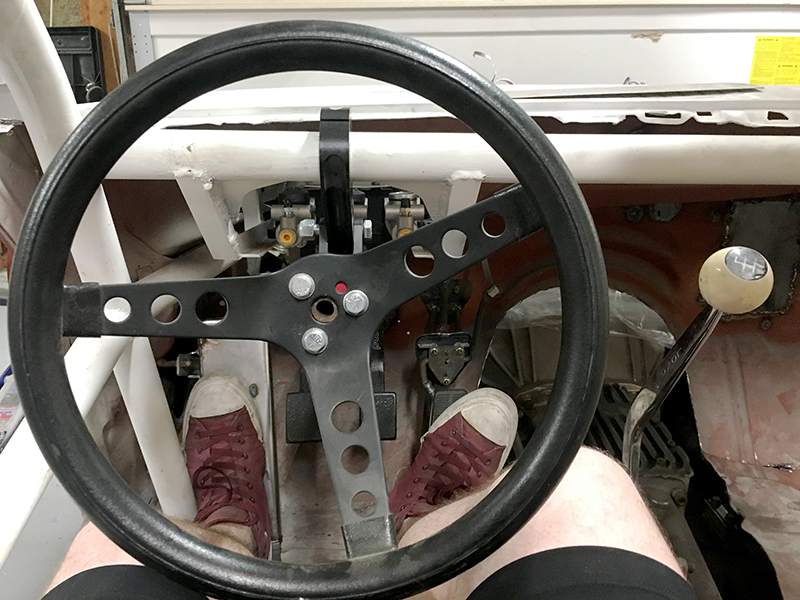
I'm happy to report that everything is comfortable, strong, and should make driving this pig a breeze.
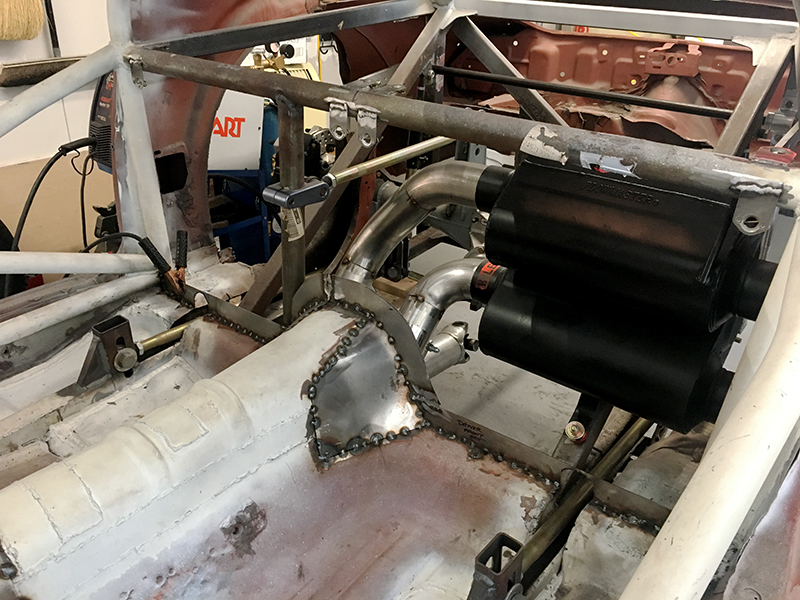
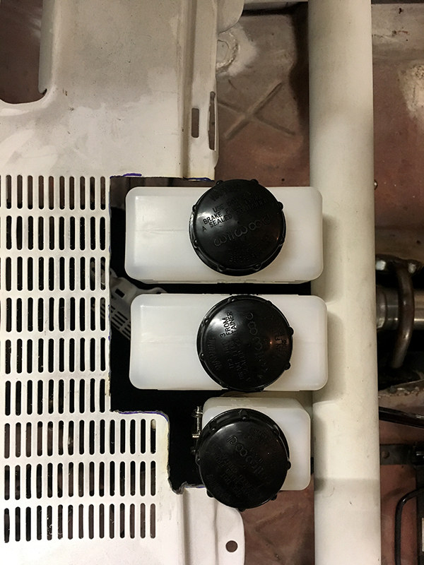
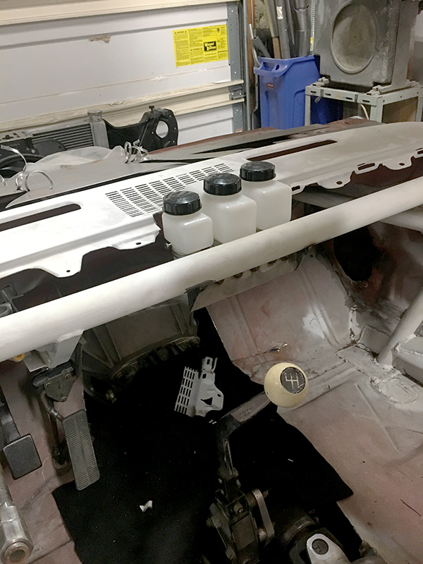
A braking and clutch system is no good without a reservoir, or in this case three. Since I won't be using the radio in this car, the grill area gave up it's life to mount them and give me a quick way to visually check levels before every run.
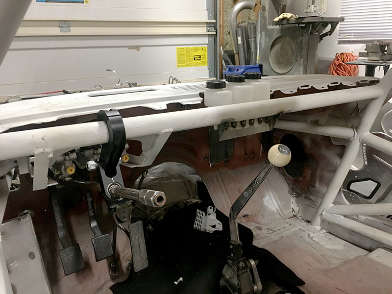
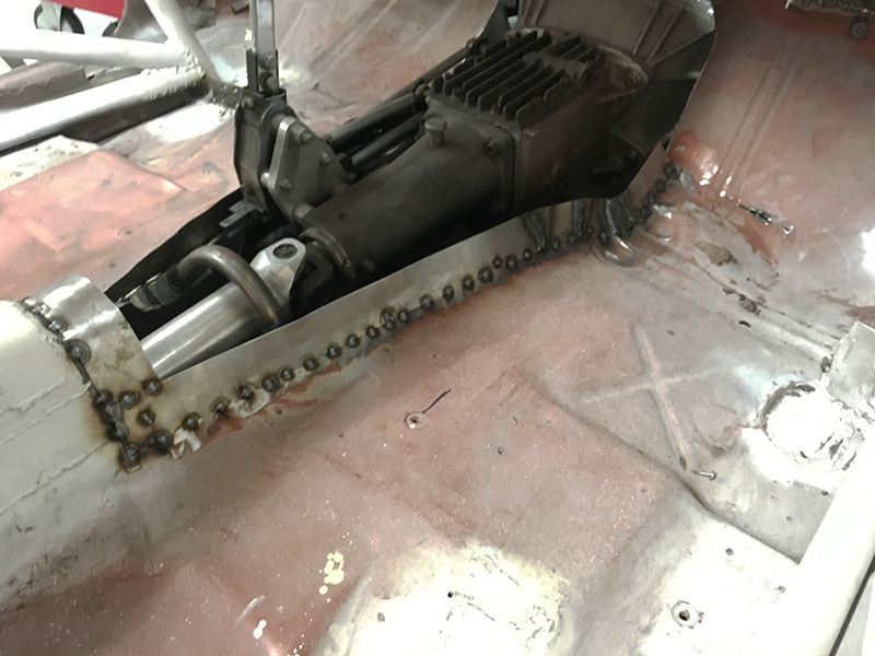
Last bit was working on continuing the flange for the trans tunnel. This was ultimately my undoing, as contorting to weld this did a number on my back, ending my week of work on the car a little early.
So, not as far as I wanted to get, but a great distance along. I still have a few more things to do, but I have started to pull the car back apart so I can get it cleaned, sanded, and tub painted before it gets too cold here.
Thanks for checking in!
So I've actually been in the process of taking the car apart for the "last" time so I can do my finish welding and start to prep for paint.
I was looking through my phone, and I realized that I had pictures of the finished transmission flange and one of the ballast racks that I hadn't shared.
Here is the transmission flange. I've got poster board on the way so I can make a template for the cover.
![]()
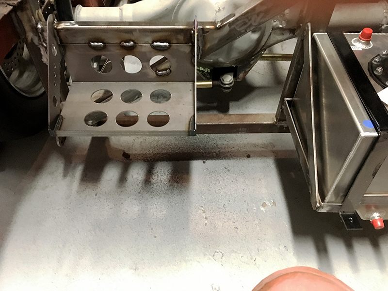
Here is the rack. It's made from some angle stock and is welded to the factory frame and the rear "box" structure. I'm also going to add an upright to the frame to keep the 100-150lbs of lead from stressing the structure. This should hold two or three lead bricks.
More updates coming soon!
Family in town and cooking didn't leave me a lot of time to work on the car, but I did start working on mocking up the rear firewall panels. These will eventually be aluminum, but poster board is way easy to work with at first. These are the removable panels, so if I have to adjust things or service them I will be able to. The outside perimeter (which I haven't done yet) will be riveted in and a little more "permanent."
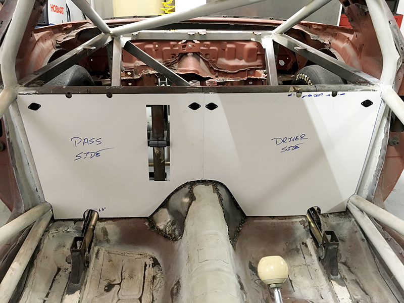
When Larry gets the templates he will come up with a creative way to cover the attachment point for the upper link, since it sticks out about a 1/2" inch.
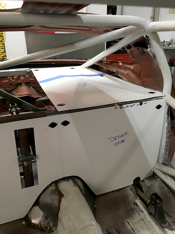
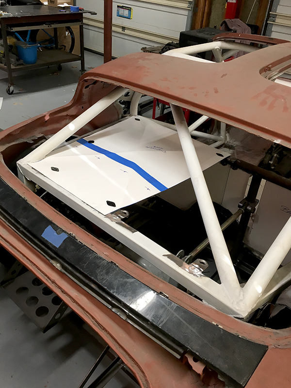
Almost hidden away.
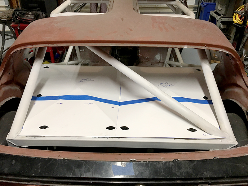
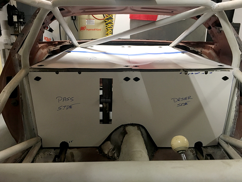
I put some folds in the paper to keep it more rigid when I was working with it. Larry will bead roll some ribs in the actual material for strength.
You'll need to log in to post.


