Lol steady eddy man. Just try to sort out one thing each time you work on it. Over the last 3 months I put MS1 fuel and spark on a 2.0 16v vw and I can honestly say it's been the most trouble free megasquirt experience I have had to date. Your not far from firing this thing up. Just need to build your flyback circuit for the low impedance injectors and get your tach inputs and spark outputs set up.
As westypoo said above, it is super easy to use the CE1/CE2 fuse block as your main and fuel pump relays (he helped me do the same) making the wiring much easier and cleaner. Your closer than it seems, just gotta grind it out to the finish.

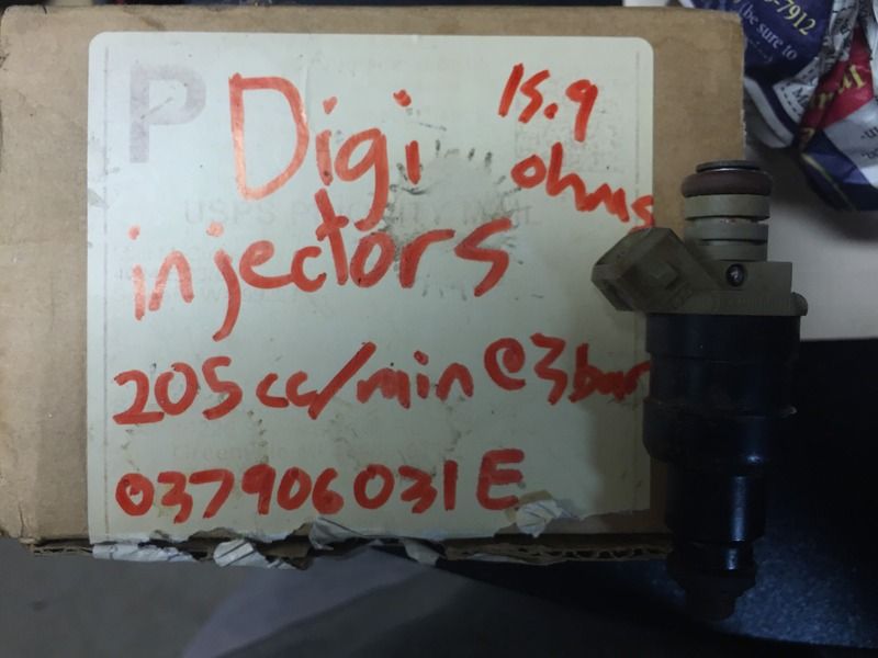
Doc Brown wrote: Here is some MS setup data for the injectors you have pictured. The Bosch 280150357 is a low impedance injector. As I recall, Megasquirt defaults to High impedance in the setup. You'll want to read up on how to set up low Z injectors. The dead time or lag time is a hard number to find and you really don't want to try and figure it out. The good news is someone else published it... booyah!  Hopefully this formats OK... * 0.9ms @ 13.2v @ 42psi <-----Dead time * Battery voltage correction: 0.11ms/v * Flow rate: 330cc @ 42psi
which I'm sure is all relevant and helpful, but it's like I have no idea what that means or how to process/apply any of that information. In your post you said...
2K4Kcsq wrote: Just need to build your flyback circuit for the low impedance injectors and get your tach inputs and spark outputs set up.
...and I'm like great. But what? I don't know how. what's a flyback circuit? etc. My brain goes dumb. Same with the well intended advice of Paul:
Paul_VR6 wrote: For a VW hall you need to be using low-to-high, usually you'll have tachselect to xg1 and a pullup inside the unit on the other side of the opto isolator. I am not sure if the mods you have will work (I have had them not work in the past). Check the manual for the current best practice modifications.
I have read the manual multiple times but nothing sticks. It's like reading French. I'm thinking I'm just not cut out for interpreting this type of thing. Megasquirt was probably a bad idea, or I just need somebody else who can decipher this to coach me through with all the way down to a dummy level. I'm putting out a feeler to a local acquaintance who I'm hoping can come help with this final grind part. it's overwhelming. 
Those of us who have done it and read it have a bad habit of paraphrasing the steps. And I can totally relate to the words in the manual not taking hold in the brain. Unfortunately the manual is the best place to read about things like the flyback circuit for low impedance injectors. And when there is a void in the manual the best place is the msextra support forums. The moderators work pretty hard to answer all the questions they can and have helped me out before.
If I were in your position I'd just get a set of high impedance injectors so you don't have to do any more board mods. If money is an issue I'd sell you 5 audi 20v high impedance injectors for whatever it cost to ship them. They are too tall for my setup but they would work quite well in yours I bet. Just saying.
The low impedance injectors want a lot of power to open, however once they open they don't need a lot of power to stay open. They are a bit tricky to set up for a beginner. There are two different methods folks use to get them to work. You can set the PWM (pulse width modulation) or use a high power resistor on each injector to limit the current. Some complex math and electrical theory is involved but the resistor method is less risky and works just as well as the PWM.
The best bet is to switch to high impedance injectors for the time being. Once you gain some more confidence you may want to go back and fool with the low impedance units.
The process may seem overwhelming at first but one you get the engine running things should start to make sense.
My first attempt was somewhat successful, however I had a lot of the setup info completely wrong.... and the car ran... not very good but it ran.
2K4Kcsq wrote:
If I were in your position I'd just get a set of high impedance injectors so you don't have to do any more board mods. If money is an issue I'd sell you 5 audi 20v high impedance injectors for whatever it cost to ship them. They are too tall for my setup but they would work quite well in yours I bet. Just saying.
Thanks for the advice. I'm going to dig out a box of injectors I have in the garage this weekend and see what they are, or if they'd be a better fit for the existing setup.
Doc Brown wrote:
The low impedance injectors want a lot of power to open, however once they open they don't need a lot of power to stay open. They are a bit tricky to set up for a beginner. There are two different methods folks use to get them to work. You can set the PWM (pulse width modulation) or use a high power resistor on each injector to limit the current. Some complex math and electrical theory is involved but the resistor method is less risky and works just as well as the PWM.
The best bet is to switch to high impedance injectors for the time being. Once you gain some more confidence you may want to go back and fool with the low impedance units.
The process may seem overwhelming at first but one you get the engine running things should start to make sense.
My first attempt was somewhat successful, however I had a lot of the setup info completely wrong.... and the car ran... not very good but it ran.
Good info.
Well some progress I guess. I bought a wideband setup from DIYAutotune via the Innovate LC2 controller and green gauge:
https://www.diyautotune.com/product/innovate-standalone-gauge-kit-w-lc-2-green-db-gauge-3873/
...as well as some key pieces I was lacking, a USB/Serial adapter, and the DB9 tuning cable. The laptop I was hoping to use has a bad motherboard, so I guess I'll steal the wife's macbook pro and download tunerstudio on that.
As for actual progress on the car, I unburied it from the things it had collected, and emptied it so I could make some sense of things. Started plotting the trunk battery location, and laying wiring through the car. Hope to make some solid progress over the long weekend here.
23 days away from target track day. 

de80q
Reader
5/27/16 7:17 p.m.
A much as wiring sucks, take your time and pay attention to what you put where. I have done it twice now in my audi, and now that it's done, it works great and it pretty clean.
So I have these injectors in my stash, would it be worth swapping out to these for initial setup or should I do whatever mods (hardware or programming?) to make the currently installed low impedance injectors work?
I have some time this weekend so hope to get some work in on the car.
good up to 120hp on 4 cylinder gas motor
Well to show some actual progress i wrapped up the rear half of my battery relocation.
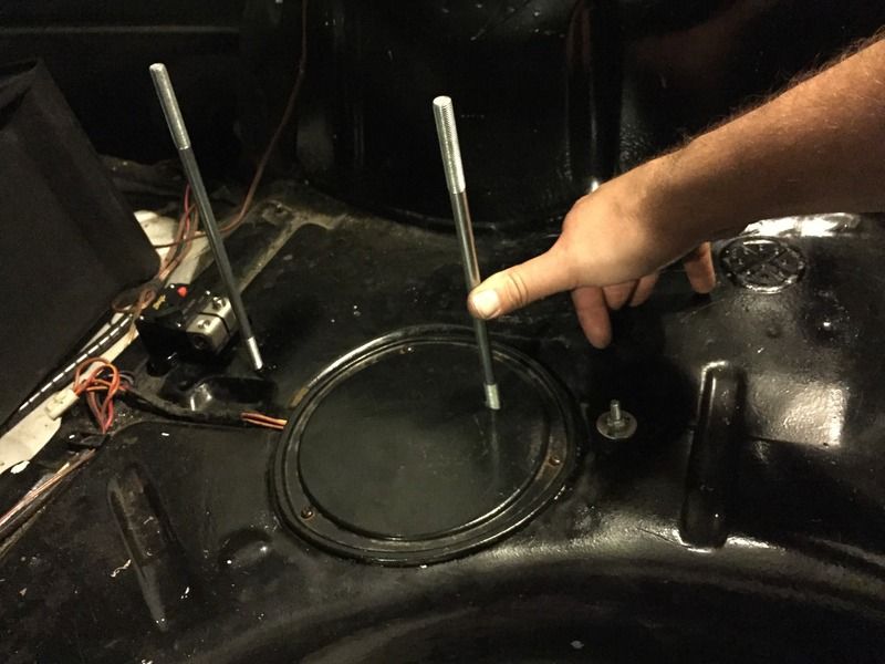
I bought a Moroso sealed battery box setup. The problem I had was that the location I wanted to put it, the threaded rod hold downs ended up right over the fuel pump and access door, with nothing good to bolt it to.
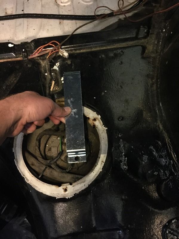
So I decided to build a simple bracket to span the gap.
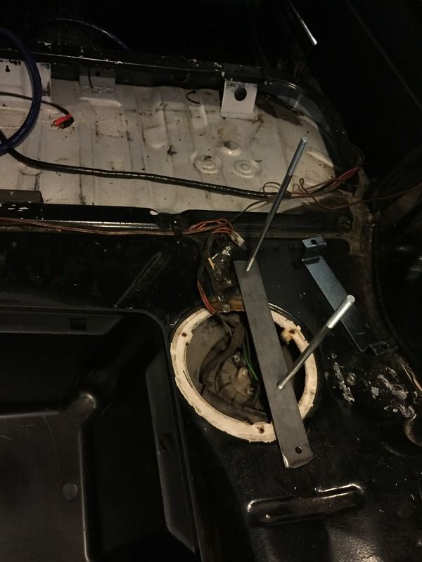
I wanted the access door still accessible, so the bracket mounts below the trunk floor but above the fuel tank.
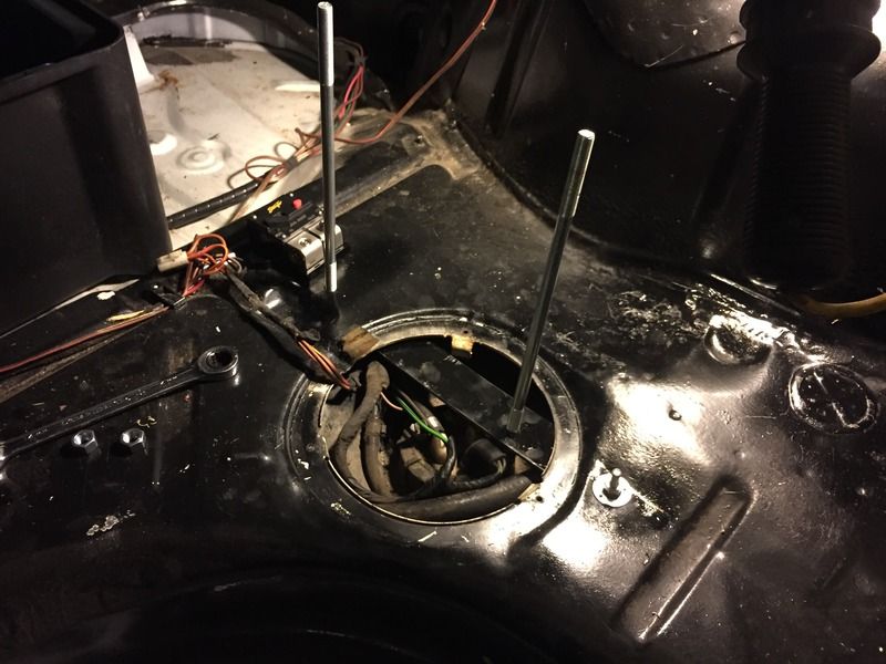
Made a template to measure right spot to drill the hole in the access door and voila.
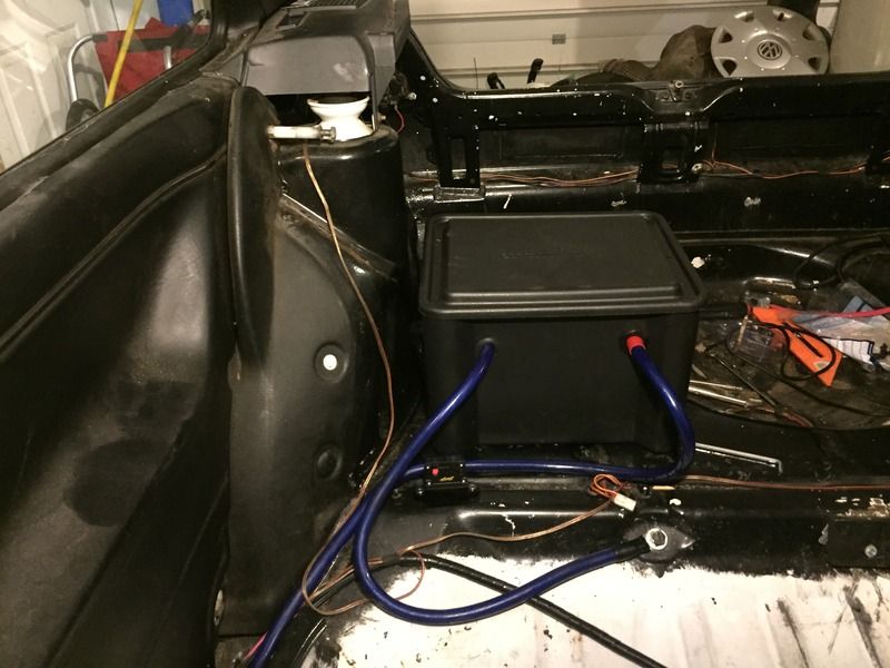
So now the battery box sits on the passenger side, right tight up against where the rear seat back would be in case I bolt rear seats back in.
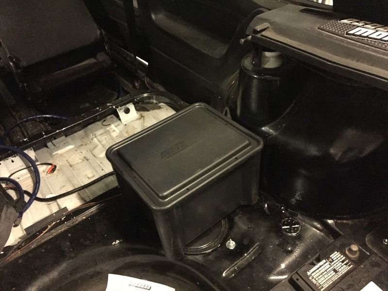
I picked up a 300amp breaker, used some PCV grommets for the cables through the side, and put the vent tube out through the wheel well. I had some 1/0 stereo cable laying around from years ago which was overkill but free. I need to add the fasteners to the box lid, and pick up a few cable half straps to secure the routing, but it's mostly done.
I have 8x new 42lb if you need something. Will cut a good deal.
xflowgolf wrote:
bentwrench wrote:
good up to 120hp on 4 cylinder gas motor
Hmmm, that's a bit weak.
Those injectors are 19.5lb
The HP rating I came up with was conservative
With an 80% duty cycle and a .52 BSFC - Modern Stock Engine or Light Modifications Engine
Normally aspirated 1600 or 1800 motor at the limit on a 2.0l
42# injectors may provide a less than sastisfactory idle and low speed performance because they tend to slobber at small openings.
However if you are going boosted, the 42's would be good for 320 HP. Use a boost referenced fuel pressure regulator to reduce fuel pressure out of boost will help the idle and low speed operation of the 42# injectors
bentwrench wrote:
Those injectors are 19.5lb
The HP rating I came up with was conservative
With an 80% duty cycle and a .52 BSFC - Modern Stock Engine or Light Modifications Engine
Normally aspirated 1600 or 1800 motor at the limit on a 2.0l
Yeah this is a 2.0 16V.
I think my current plan is to figure out what is needed to make the injectors that are already in the car work. No plans to boost right now.
If you can crank the fuel pressure to 4bar they will be plenty big.
Paul_VR6 wrote:
Also on the injectors, measure the resistance yourself. If you have a full board build you have the current limiting circuitry. You will just need to enable hardware pwm. Its all in the manual. Msextra.com
Alright, so I found this in the manual. Low impedance injectors, up to 4 of them, but with resistance greater than 2.4ohm, use PWM current limit. They should not need injector resistors or a fly back board unless resistance is less than 2.4ohm.
Since these are 2.8ohm, I should be able to use pulse width modulation control only.
Aha! ...which makes this make sense:
Doc Brown wrote:
Here is some MS setup data for the injectors you have pictured
* 0.9ms @ 13.2v @ 42psi <-----Dead time
* Battery voltage correction: 0.11ms/v
* Flow rate: 330cc @ 42psi
Reading the manual, with the above settings, 330cc = ~31lbs./hr. which are sized quite reasonably for this application.
This is finally starting to click. 
If you have a V3 board with ALL the components, all you need to do is enable hardware PWM current limiting in the injector settings. On a V3 there is no need for mods or a flyback board. The flyback boards or P&H boards that's only for V2.2 and lower (OLD!) or for use with uS or MS3-Pro as neither has the PWM current limiting circuitry on board.
Paul_VR6 wrote:
If you have a V3 board with ALL the components, all you need to do is enable hardware PWM current limiting in the injector settings. On a V3 there is no need for mods or a flyback board. The flyback boards or P&H boards that's only for V2.2 and lower (OLD!) or for use with uS or MS3-Pro as neither has the PWM current limiting circuitry on board.
Yes I have a V3 board.
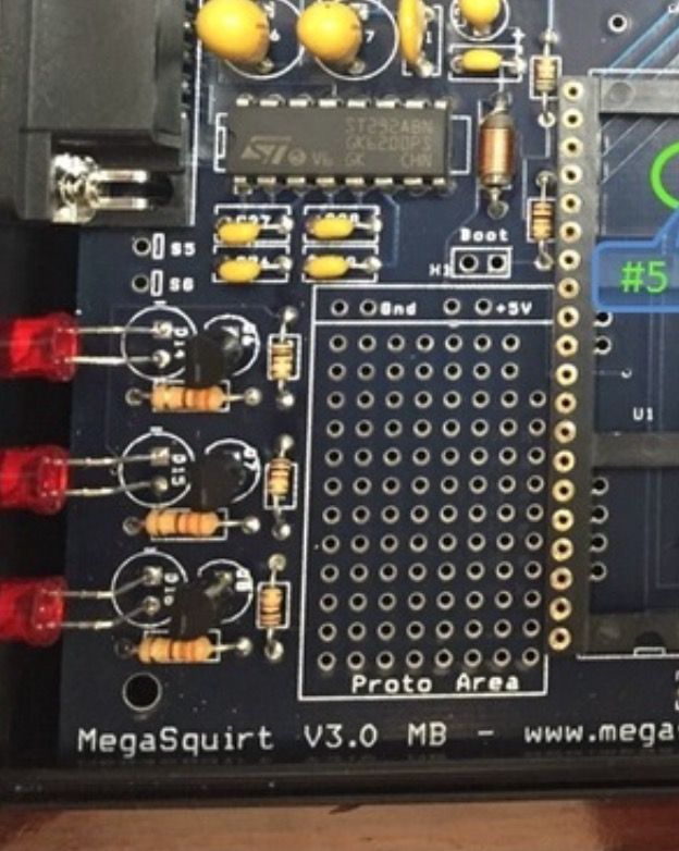
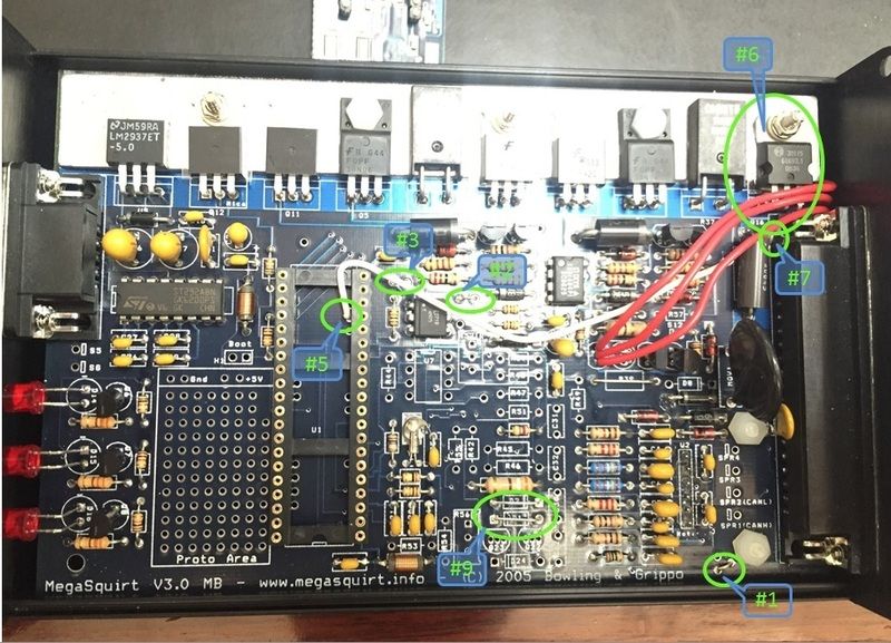
I'm not sure what is meant by "ALL the components" though? This board was assembled by the PO. (Ignore the notations)

Excerpt from megamanual:
69. Once again you have a choice to make about whether to install certain components. In this case, you need to decide if you wish to install the PWM flyback damping circuit as well as the standard flyback circuit. The PWM flyback damping circuit is useful primarily for those running pulse width modulation (PWM) with low-impedance injectors. However, it will work fine if you install it with high impedance injectors. If you prefer to install only the standard flyback circuit, skip ahead to step #70: To install the PWM flyback damping circuit:
Install R30, R31, R34 and R35 {270QBK-ND, red-violet-brown}. R30 and R31 are near R37 on the heat sink, R34 and R35 are near Q9.
Install R32 and R36 {1.0KQBK-ND, 1K Ohm, brown-black-red}. These are located besides the resistors you installed in the last step.
Install Q9 and Q12 {TIP125TU-ND}. Bend the leads to fit in the holes so that the hole in the tab lines up with the hole in the heat sink. These transistors mount to the heat sink, but they MUST have an insulator between the transistors and the heat sink. Use the insulator kits for this {4724K-ND}. You may have to trim the mica insulator somewhat to avoid hitting the transistor leads - use a sharp pair of scissors. Use heat transfer compound between the component, mica insulator, and the heat sink.
After assembly, check that you have very high resistance between the metal tab of both Q9 and Q12 and the heat sink. If you get less than about 60K Ohms (± 20K Ohms) resistance, you MUST correct it. Usually chamfering the bolt hole and sanding the heat sink lightly will solve the problem. Once you have ~60K Ohms or more resistance between the tab and heat sink, solder the leads to the PCB.
Install Q10 and Q13 {2N3904FS-ND}. The flat side of the transistors face the heat sink. These are located near Q9 and R37 on the heat sink. The pins are very close together, use a clean tip, and be careful not to bridge the joints.
There are no jumpers to install.
Even if you have installed the PWM flyback damping circuit, you should install the standard flyback circuit as well (step #70).
Go through that list and verify all components are there. If so, you are good.
Paul_VR6 wrote:
Excerpt from megamanual:
69. Once again you have a choice to make about whether to install certain components. In this case, you need to decide if you wish to install the PWM flyback damping circuit as well as the standard flyback circuit. The PWM flyback damping circuit is useful primarily for those running pulse width modulation (PWM) with low-impedance injectors. However, it will work fine if you install it with high impedance injectors. If you prefer to install only the standard flyback circuit, skip ahead to step #70: To install the PWM flyback damping circuit:
Install R30, R31, R34 and R35 {270QBK-ND, red-violet-brown}. R30 and R31 are near R37 on the heat sink, R34 and R35 are near Q9.
Install R32 and R36 {1.0KQBK-ND, 1K Ohm, brown-black-red}. These are located besides the resistors you installed in the last step.
Install Q9 and Q12 {TIP125TU-ND}. Bend the leads to fit in the holes so that the hole in the tab lines up with the hole in the heat sink. These transistors mount to the heat sink, but they MUST have an insulator between the transistors and the heat sink. Use the insulator kits for this {4724K-ND}. You may have to trim the mica insulator somewhat to avoid hitting the transistor leads - use a sharp pair of scissors. Use heat transfer compound between the component, mica insulator, and the heat sink.
After assembly, check that you have very high resistance between the metal tab of both Q9 and Q12 and the heat sink. If you get less than about 60K Ohms (± 20K Ohms) resistance, you MUST correct it. Usually chamfering the bolt hole and sanding the heat sink lightly will solve the problem. Once you have ~60K Ohms or more resistance between the tab and heat sink, solder the leads to the PCB.
Install Q10 and Q13 {2N3904FS-ND}. The flat side of the transistors face the heat sink. These are located near Q9 and R37 on the heat sink. The pins are very close together, use a clean tip, and be careful not to bridge the joints.
There are no jumpers to install.
Even if you have installed the PWM flyback damping circuit, you should install the standard flyback circuit as well (step #70).
Go through that list and verify all components are there. If so, you are good.
Thanks Paul.
I verified all of these components are in place per the manual. This diagram is helpful in locating the locations quickly.

In my previous images I was able to do a quick visual check on all of those locations to see the components installed.
Question for the megasquirt gurus. On the hall sender, since I'm using the 1K pullup resistor on the signal across pin 24 and 28 (12V supply), do I supply the hall sender itself a 5V supply (from pin 26 on DB37 connector) or do I need to supply it 12V from another source?
i.e. 3 wires on Hall sender plug.
1) Ground
2) Signal (to pin 24 on connector... w/ pullup relay)
3) Power. 5V off MS or 12V?
...I also started a build support thread on the msextra forums that hopefully will be moderator approved soon since I'm a noob.
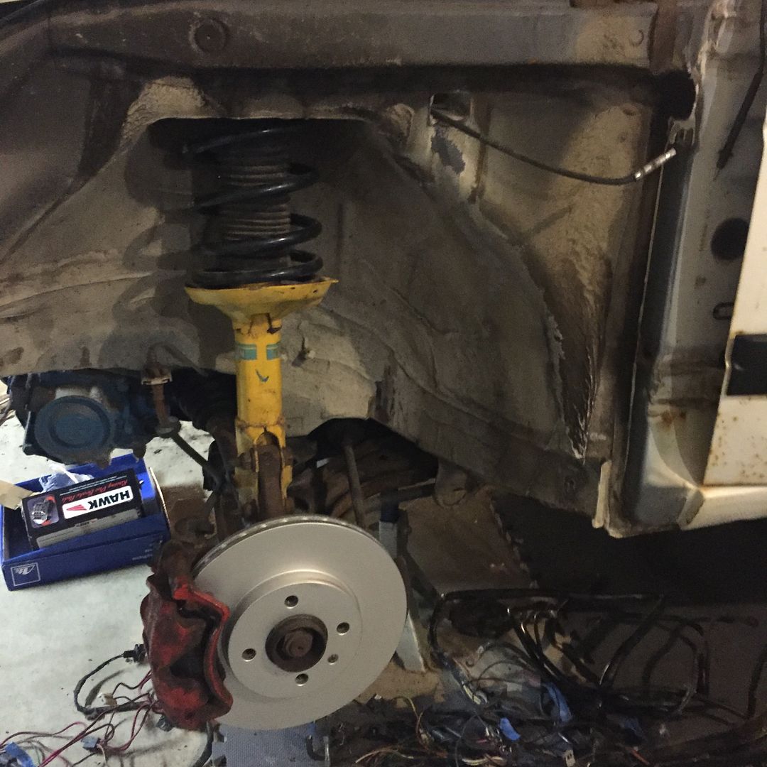
I scored a cheap H&R / Bilstein setup off a local forum, and I installed new rear brakes and wheel bearings. It was my first time hammering in bearing races. New slides as well. Rear should be buttoned up. 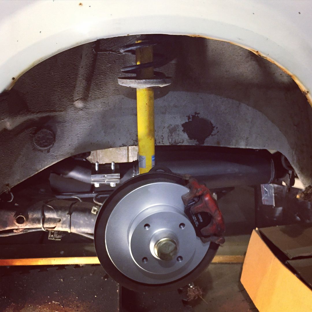 Next up is doing the same up front and installing the strut tower brace. I have to order some longer lug bolts or wheel studs as well for the thicker 14" BBS wheels I have, and then I can set it back on the ground.
The Hall sensor makes a grounding signal, but when it's not grounding the voltage (if there is any) floats.
The pull up resistor provides a positive voltage to be pulled down by the sensor when it makes the ground.
This creates a square wave signal from 0 (grounded) to +5v when open.
Some Hall sensors have this pull up built into them, some don't.
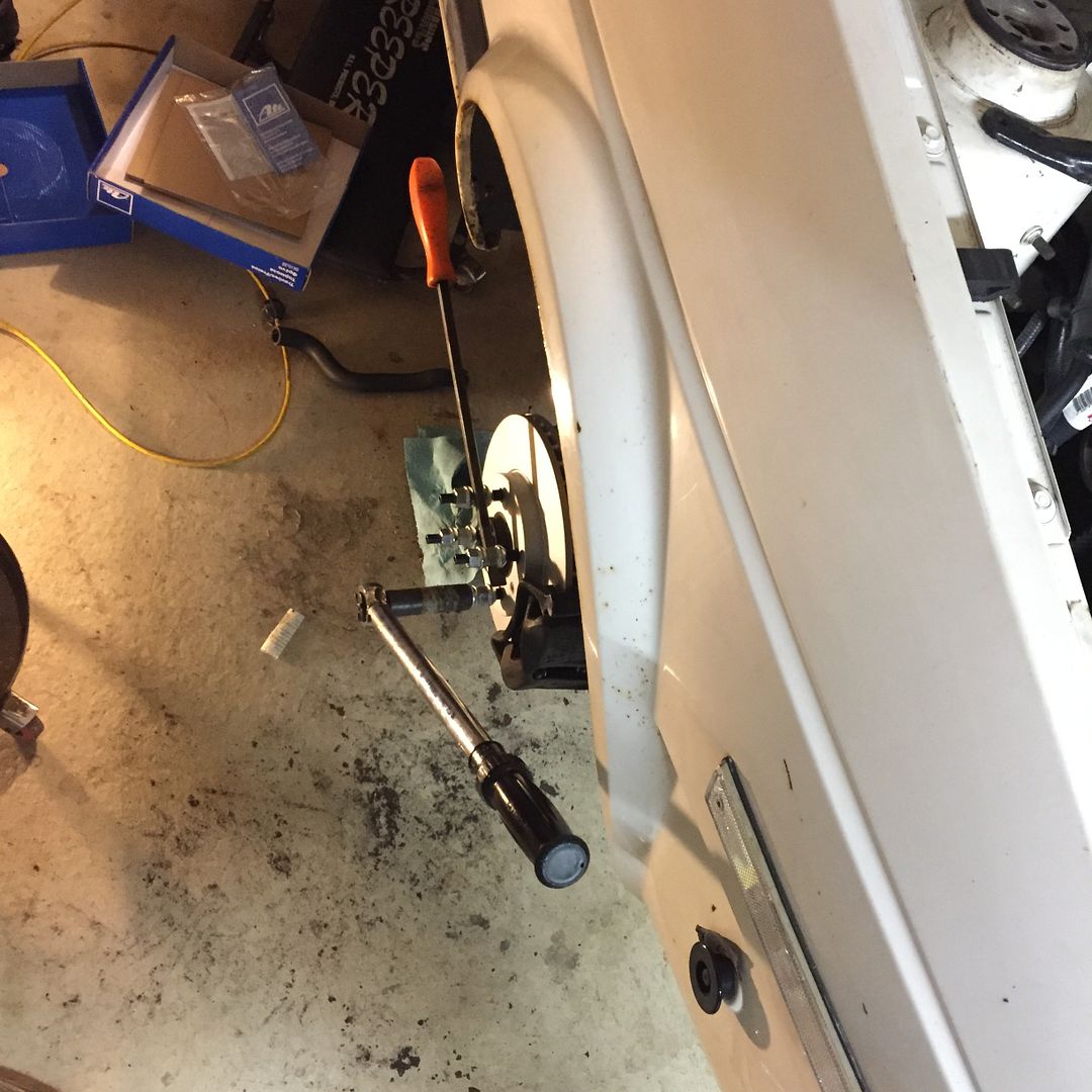
Well I got the front struts swapped, and put on new rotors and Hawk track pads.
I solved my wheel mounting problem by ordering wheel studs from Motorsport Hardware. Torqued those up, and I was ready to roll.
First time this thing has been on the ground in a long time. Geeked to see it looking like a car again.

Now to make it run. 
Just popping in to offer words of encouragement. I just read back over this thread, and all the MS talk is way over my head. I really appreciate all the pioneers who have blazed the trail, and shared what they have found. Someday, I hope to successfully megasquirt something. Thanks for sharing.


