G braces have been around since Herb Adams & his crew were racing 2nd gens back in the early 70's. The basic brace idea itself was/is a good concept which triangulates the front sub frame to the upper cowl. This reduces deflection of the stock sub frame and stiffens up the overall platform so suspension and steering components can do their job better.
The Pro-Touring F-Body Gen II adjustable G-braces shown here evolved from the simple early braces and are a great product. They're a very stout design with a nice adjustable feature that allows them to be easily installed on most 2nd gen F body's. The braces are actually much stronger than the cars they're being installed in and that is the focus of this post. By modifying the points where the forces transferred by the G-braces act on the cowl, upper control arm mounting bolt, upper control arm mount, and sub frame we can make the G braces function even better whan the car is pushed to it's limits.
In my opinion G-braces should only be used on cars with solid body mounts as a minimum, and preferably have sub frame connectors also. Doing any of the modifications discussed in this post without solid body mounts is a waste of time and money (even if you think it looks cool). Additionally, if you're not really pushing the limits of the car at auto-X, hill climbs, or on road race tracks it's doubtful the benefits of most of this additional bracing would be noticed. However I do believe the upper control arm bolt support would be a good addition to any car with any type of G-brace that uses the upper control arm cross shaft mounting bolt as the G-brace lower mounting point.
So here's my list of areas that can use a bit of improvement and what I've done. I hope this helps for those who might want to copy what I've done or come up with better ideas. As with most things the evolution will continue.
Also for those wondering, Dave at PTFB has been kept in the loop while I was designing/prototyping all these things. You can expect a new bolt on center upper G-brace to cowl support to be available from PTFB very soon. Top secret at the moment so I can't disclose details but Dave should be announcing soon. Where the ones shown below only fit low valve cover Pontiac set ups the PTFB one's will fit multiple applications for those with tall covers, LS engines etc.
- Upper cowl where G-braces attach is three pieces of sheet metal spot welded together. The G brace mounts are almost centered on the large air openings on the top of the cowl which are the weakest areas. Also the drivers side G brace is in the area of the cowl recessed for the windshield wiper motor allowing more flex in that section of the spot welded ledge the brace is mounted to.
Improvement 1. A strip of 1/8" steel plate above and below ledge creating a sandwich and bolted through the pinch welded area. Stiffens the ledge and spreads the force from the brace over a much wider area. Creates a wider thickness for shear forces transferred through the bolts to act on by doubling (or rmore) the thickness of the ledge. Provides a strong section in the center of the cowl ledge where the top of the cowl is stiffer for the additional centered mount triangulation braces I made that do not come with G-braces. The additional braces also provide lateral support. I used bolts but the sandwich plates could be welded in place.
- Stock upper control arm mount is made of 3/16" steel. It can flex and those of you who've examined them probably noticed that they've deformed over the years a bit around the forward UCA bolt hole from bumping parking blocks, tightening during alignment, or whatever. If your car's apart put a straight edge on the UCA shaft mounting face and you'll see what I'm talking about. The stock UCA bolts were splined for an interference fit. Often on the cars after many years the interference fit has been widened by movement and the splines don't engage tight any more.
Improvement 2. Weld a piece of 1/8" flat plate to the face of the UCA mount. Most of us with track cars are already running a bunch of shims on the front and rear UCA shaft bolts to get as much positive castor and negative camber as we can. The 1/8" plate eliminates one shim front/rear and eliminates one surface where things could slip/move.. The 1/8" welded plate increases the thickness of the mount to 5/16 which is a 66% increase and stiffens the mount. Additionally it gives a thicker more solid base for larger splined UCA shaft mounting studs/bolts.
- The stock UCA shaft bolts are 1/2" with a small splined base. Their intended use was to clamp the UCA shaft to the mount and accept forces applied in compression and tension. They were not intended to receive shear forces trying to wiggle and tip the bolt. With G-braces the shear forces applied by the braces are at roughly 90 degrees to the bolt AND the force is not at the base where the splines are but away the thickness of the shims and control arm shaft so leverage is involved increasing the possibility of tipping or wiggling the bolt.
Improvement 3. ARP 1/2" wheel studs with a wide spline base to replace stock UCA shaft bolts. The wide base makes the bolt more stable and spreads force over a bigger area. The spline area is also deeper which combined with the additional thickness provided by the 1/8" plate welded to the mount keeps the bolt more stable. The wheel studs are also longer allowing shims etc. to run a lot of negative camber while still easily double nutting the bolts with grade 8 nuts to prevent loosening. The ARP long studs are stronger and also allow space to utilize an additional support for the stud to transfer force to the frame horns ahead of the UCA mounts.
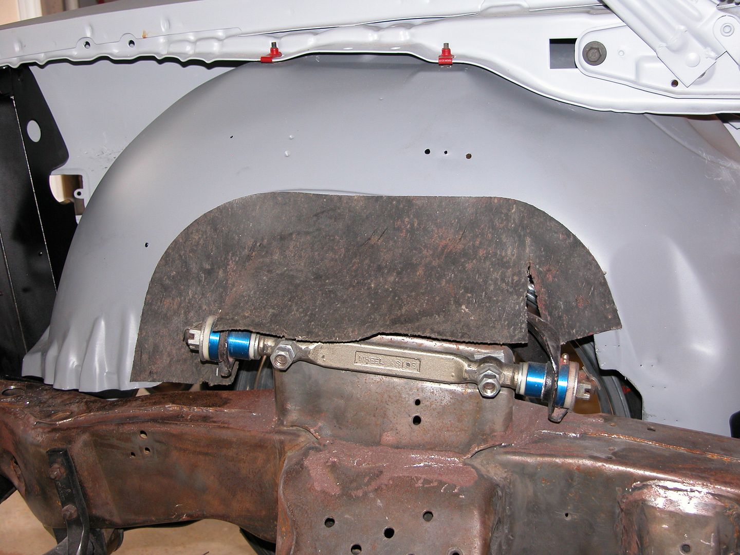
Additional improvement. Adjustable UCA bolt brace between the front UCA bolt/stud and the frame on roughly the same angle as the main tube of the G-brace.. This support transfers loads from the G-brace to the front frame horns reducing the load on the spline section of the UCA bolt by providing additional support on the other side of the G-brace to help prevent tipping or wiggling of the UCA bolt/stud. I feel this is the most beneficial modification and recommend it to anyone using any style of G braces that use the UCA mounting bolt as the lower attachment point.
Pic below is an overview showing everything mocked up but not yet fully adjusted and tightened. The sub frame will need to come out for paint after other modifications are done. The bolts and nuts are all serrated flange locking fasteners excluding the ARP studs & grade 8 nuts used for the UCA shaft mount. On the cowl, the top of the G-braces are fastened with 7/16" bolts and the other bolts (including the additional upper braces) are all 3/8". The lower supports for the UCA bolts are fastened to the frame with 1/2" serrated flange nuts/bolts.
[URL=http://s240.photobucket.com/user/NOTATA/media/The%2014%20Car%20Performance%20Therapy/005_zpsyyvci1im.jpg.html]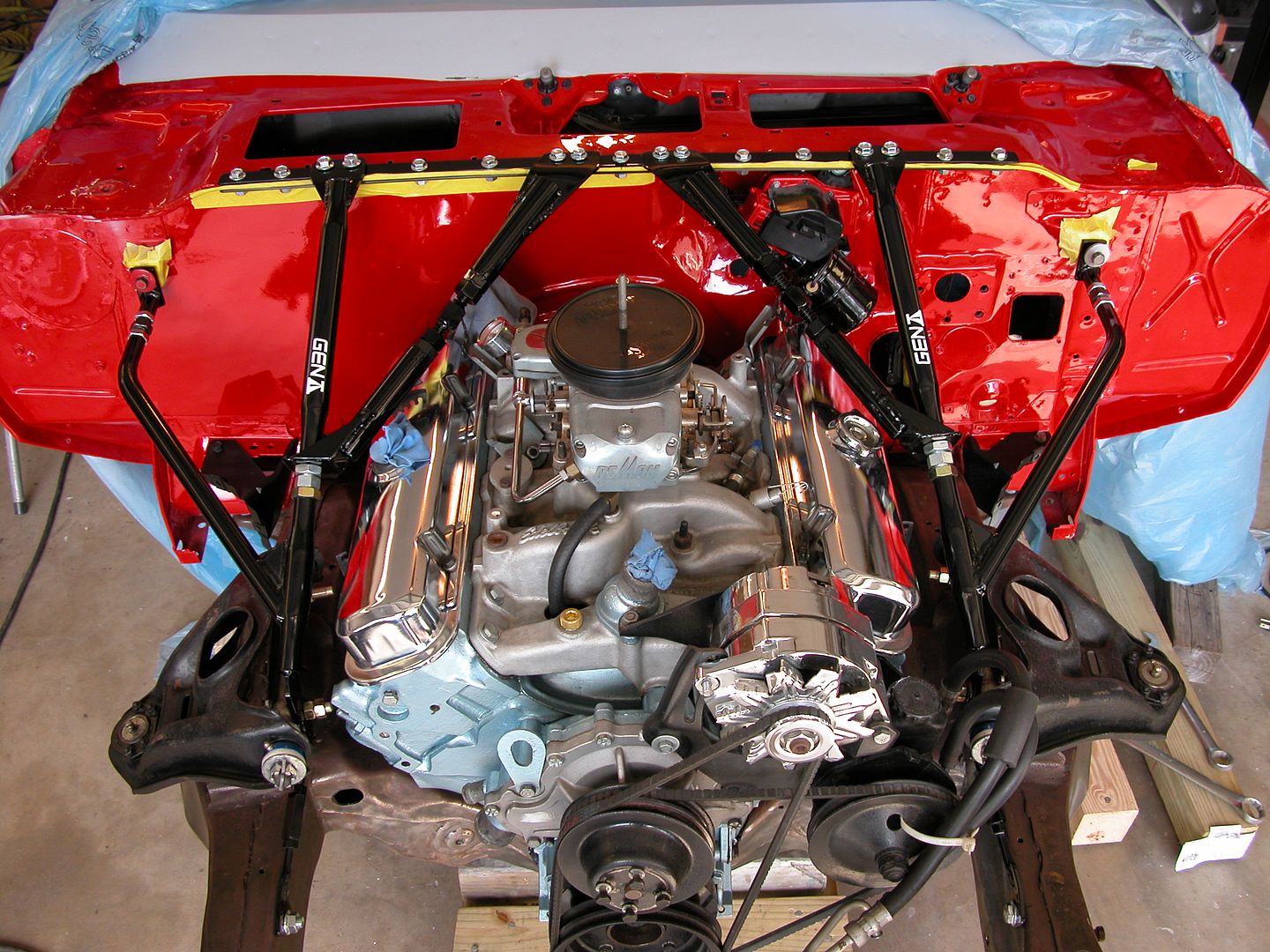 [/URL]
Pic below shows the 1/8" thick plate welded to the UCA shaft mounting surface. Note the thickness where the splines of the stud will hold the bolt more securely.
[URL=http://s240.photobucket.com/user/NOTATA/media/The%2014%20Car%20Performance%20Therapy/004%20-%20Copy_zpsqaihegpg.jpg.html]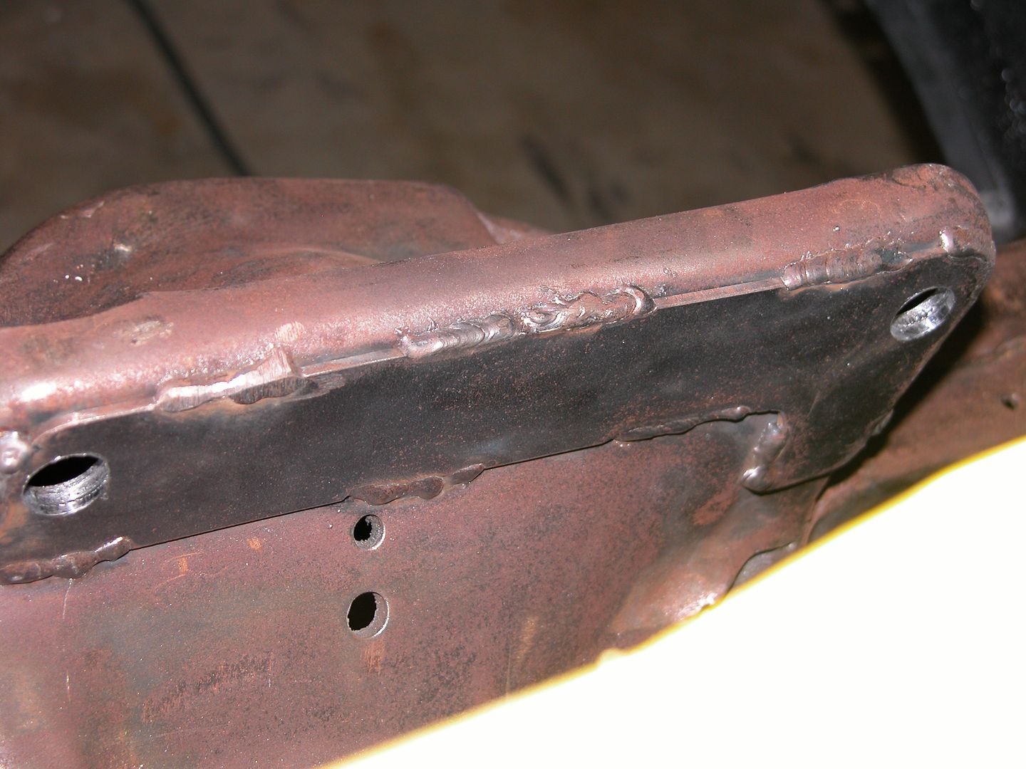 [/URL]
Pic below shows the difference between a stock mounting bolt for the UCA shaft and an ARP wheel stud used to replace them. You can see how the wider deeper spline section will support the bolt more rigidly.
[URL=http://s240.photobucket.com/user/NOTATA/media/The%2014%20Car%20Performance%20Therapy/002_zpshozi0tbe.jpg.html]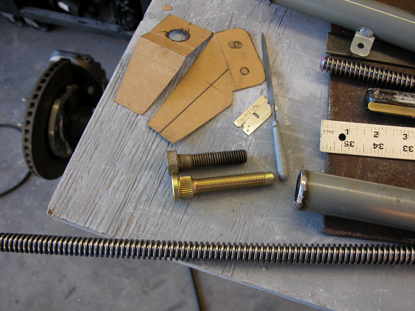 [/URL]
Pic below shows how the additional upper supports are attached to the PTFB Gen II adjustable G-braces and the angle of the lower support that is attached to the UCA bolt and sub frame.
[URL=http://s240.photobucket.com/user/NOTATA/media/The%2014%20Car%20Performance%20Therapy/007_zpsqojkvh2v.jpg.html]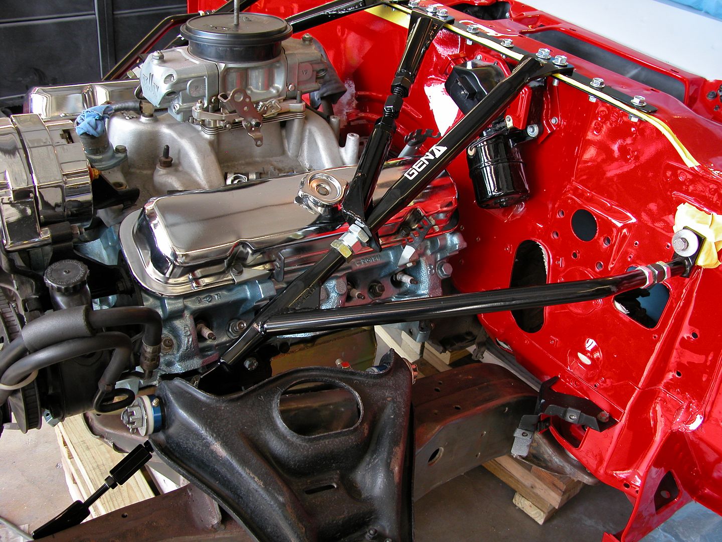 [/URL]
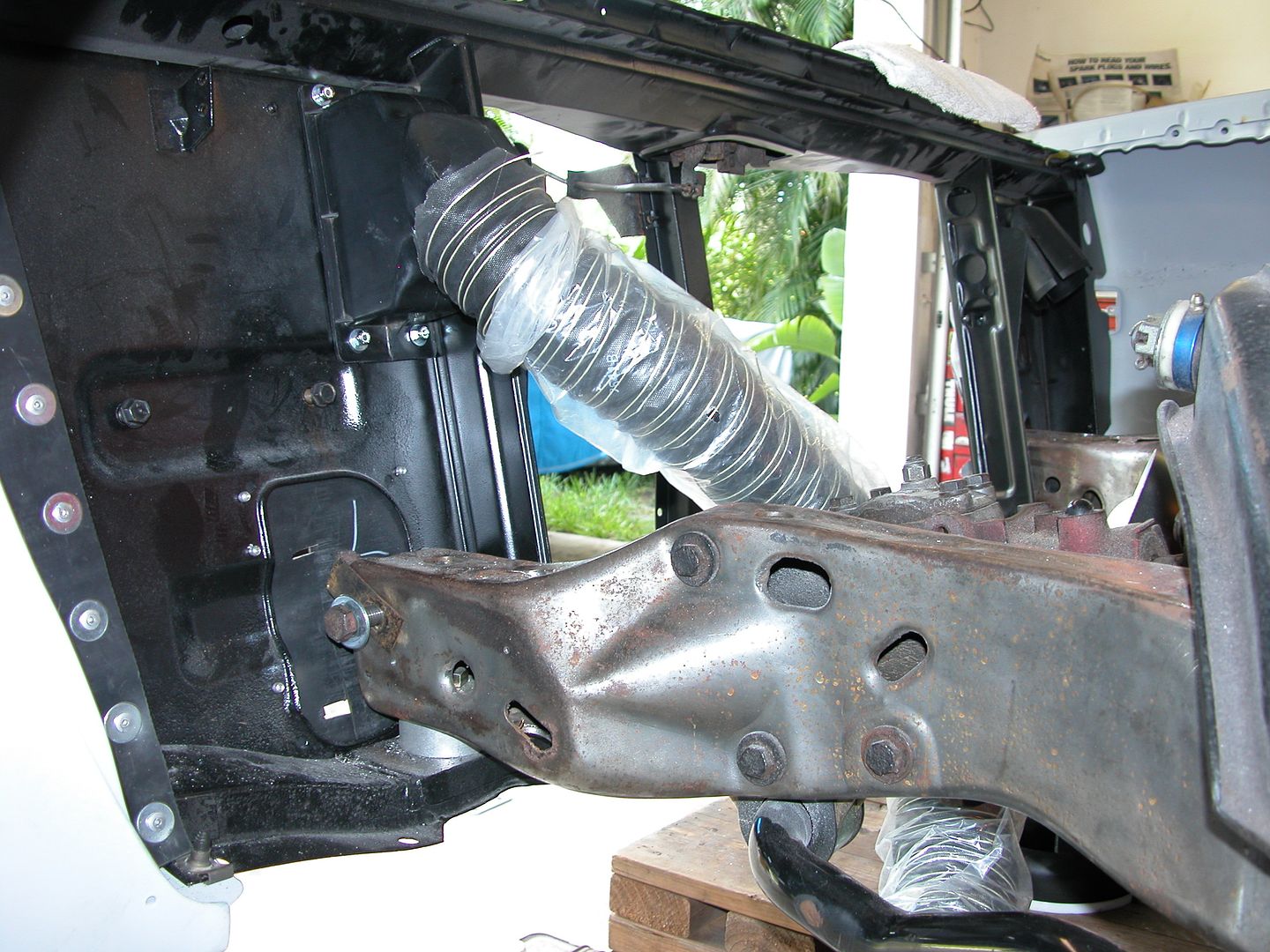
Pics below show the drivers side lower support. The unused mount on the steering box has to be cut off to provide clearance for the mounting bolt through the frame. I used 1/2" mounting bolts so I'd have a wide surface area which need to be ground down a bit for steering box clearance. Everything's close but fits. Careful marking of where the frame mounting bolt hole needs to be is critical on the drivers side. Passenger side there's plenty of room.
[URL=http://s240.photobucket.com/user/NOTATA/media/The%2014%20Car%20Performance%20Therapy/012_zps0ropnunl.jpg.html]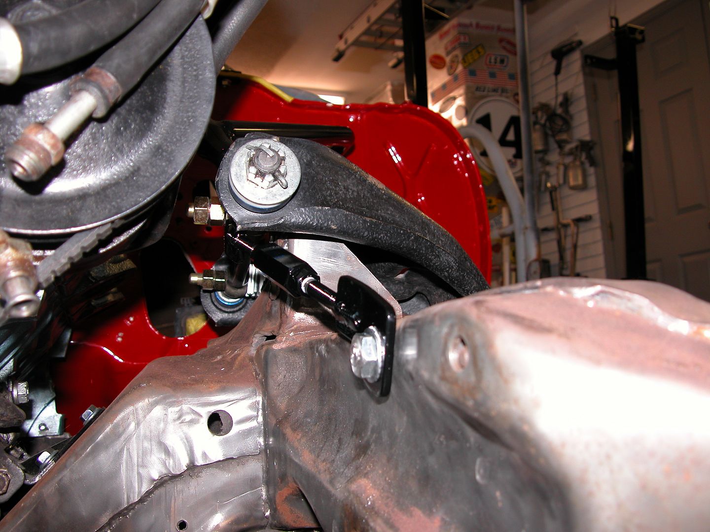 [/URL]
[URL=http://s240.photobucket.com/user/NOTATA/media/The%2014%20Car%20Performance%20Therapy/002_zpsgrgy5mkp.jpg.html]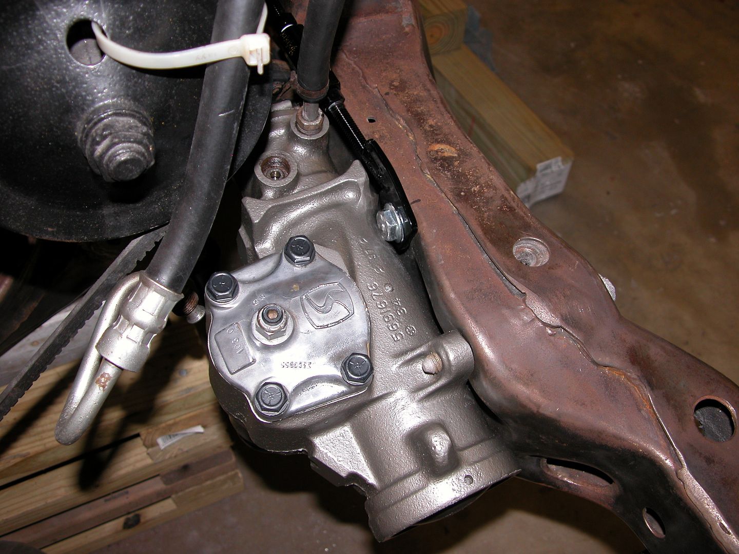 [/URL]
Pic below shows all the pieces used for the upgrades described that do not come with a set of PTFB Gen II adjustable G-braces.
[URL=http://s240.photobucket.com/user/NOTATA/media/The%2014%20Car%20Performance%20Therapy/010_zpsnih6odon.jpg.html]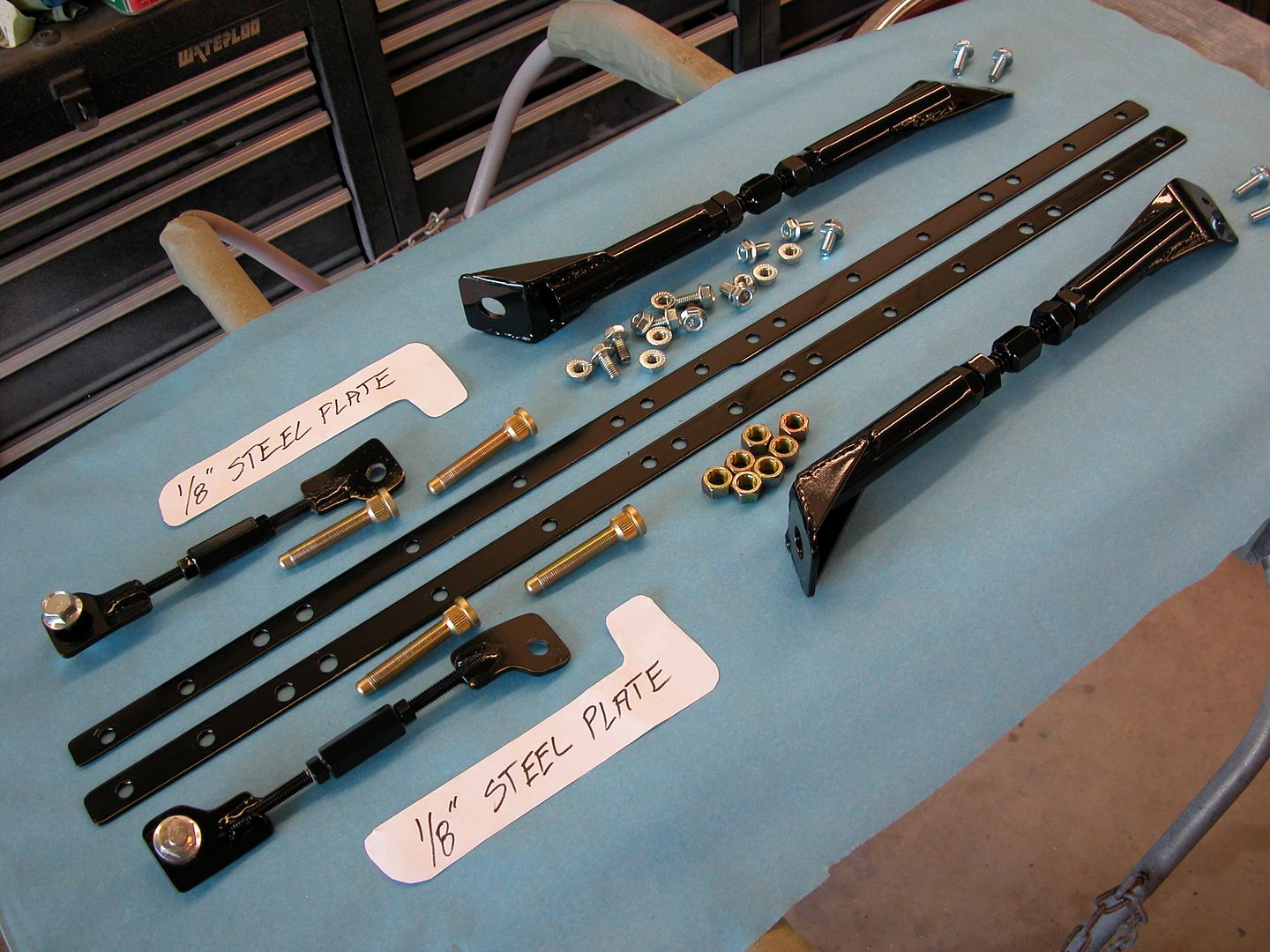 [/URL]


 [/URL]
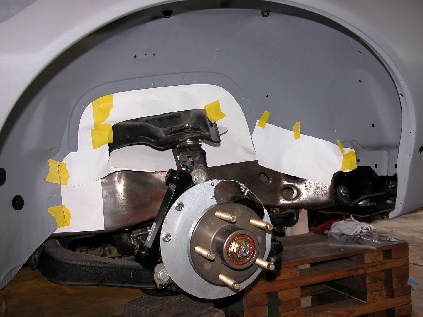 [/URL]
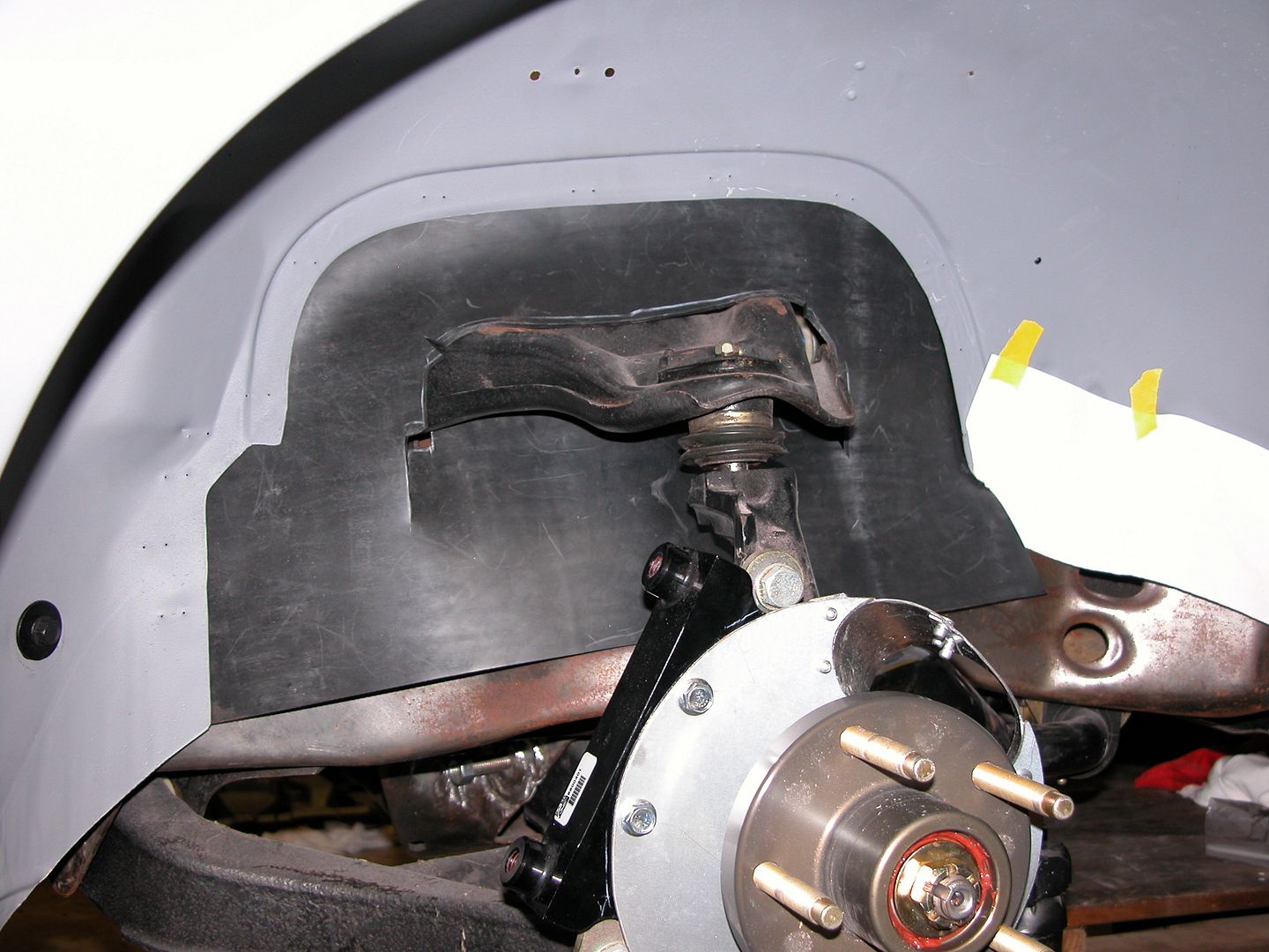 [/URL]
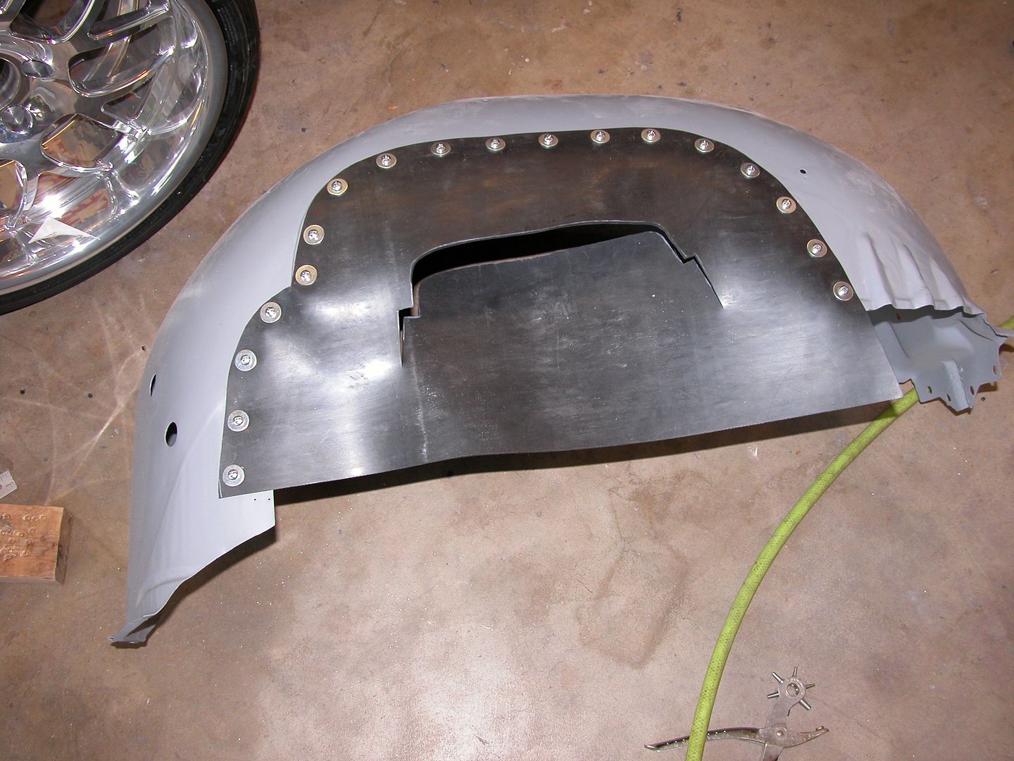 [/URL]
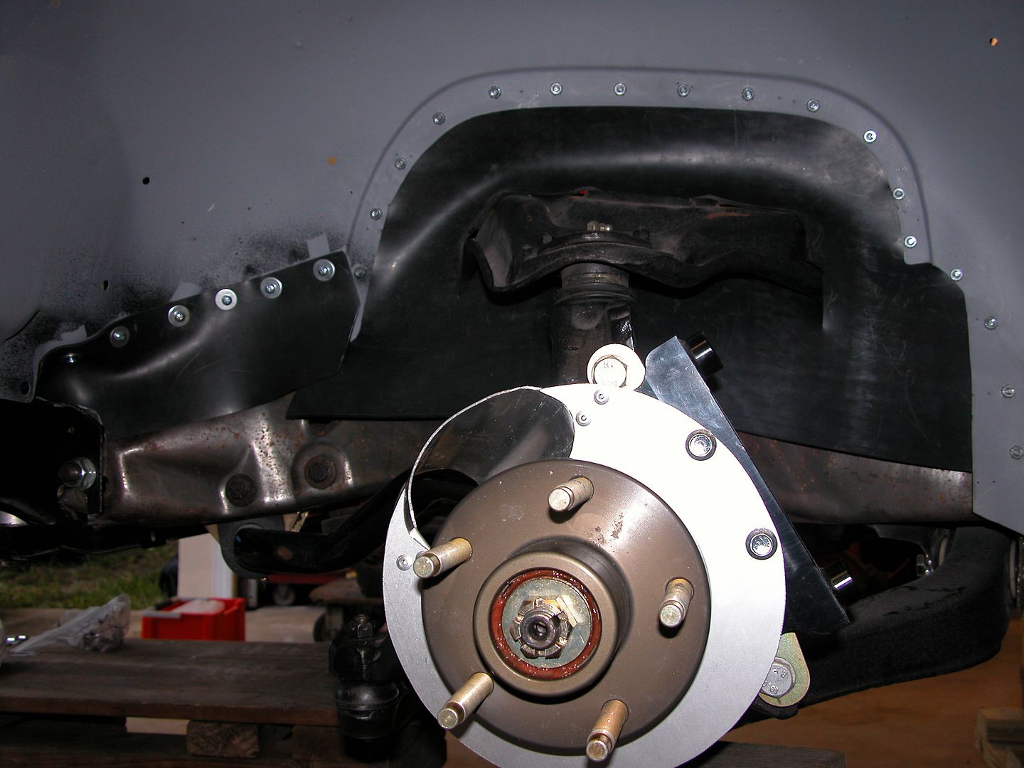 [/URL]
 [/URL]
 [/URL]
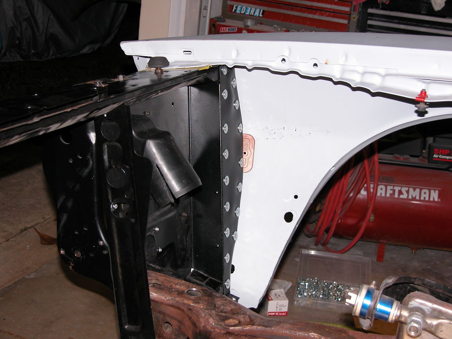 [/URL]
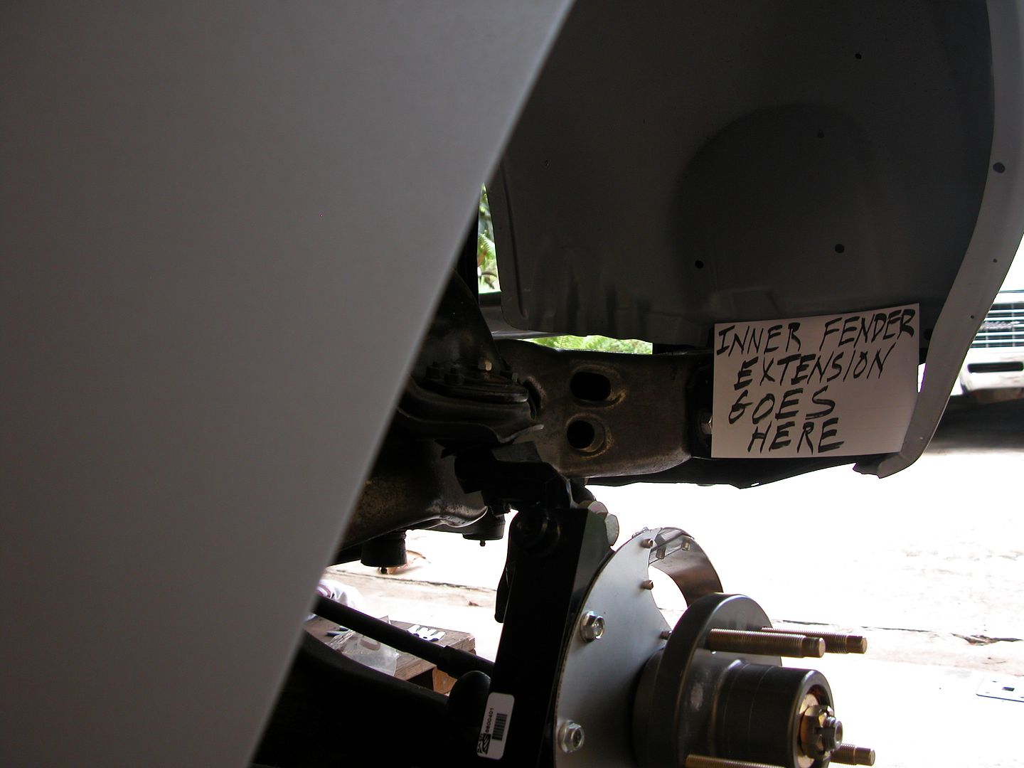 [/URL]
 [/URL]
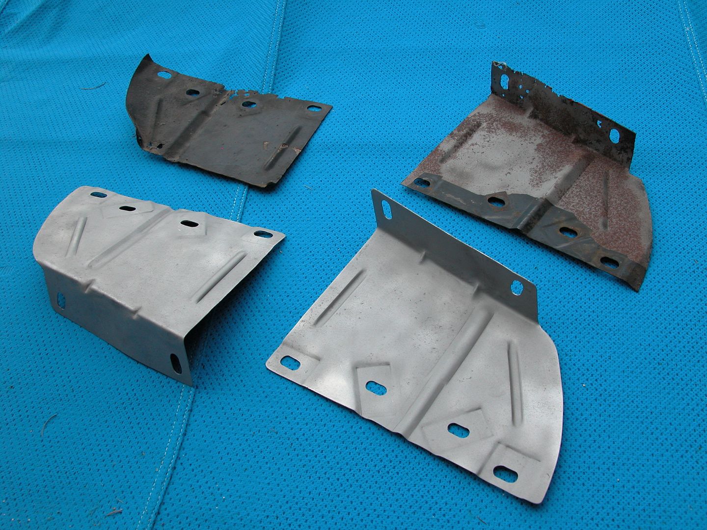 [/URL]
 [/URL]
 [/URL]
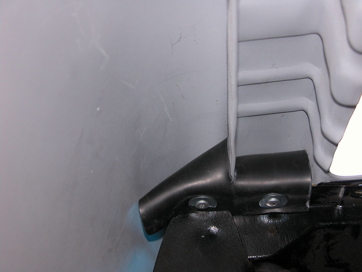 [/URL]
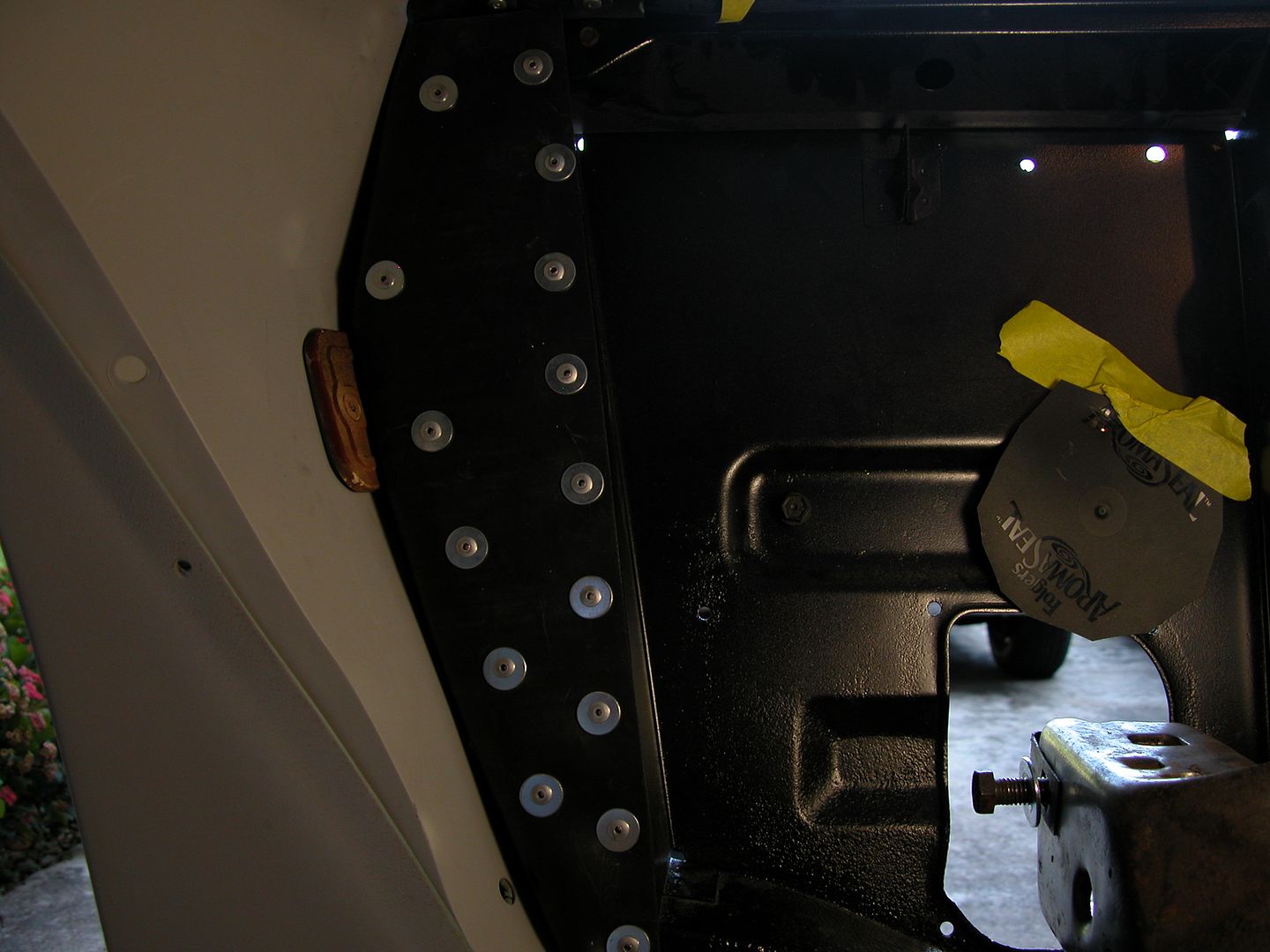 [/URL]
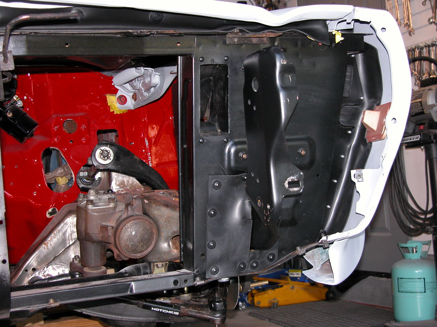 [/URL]
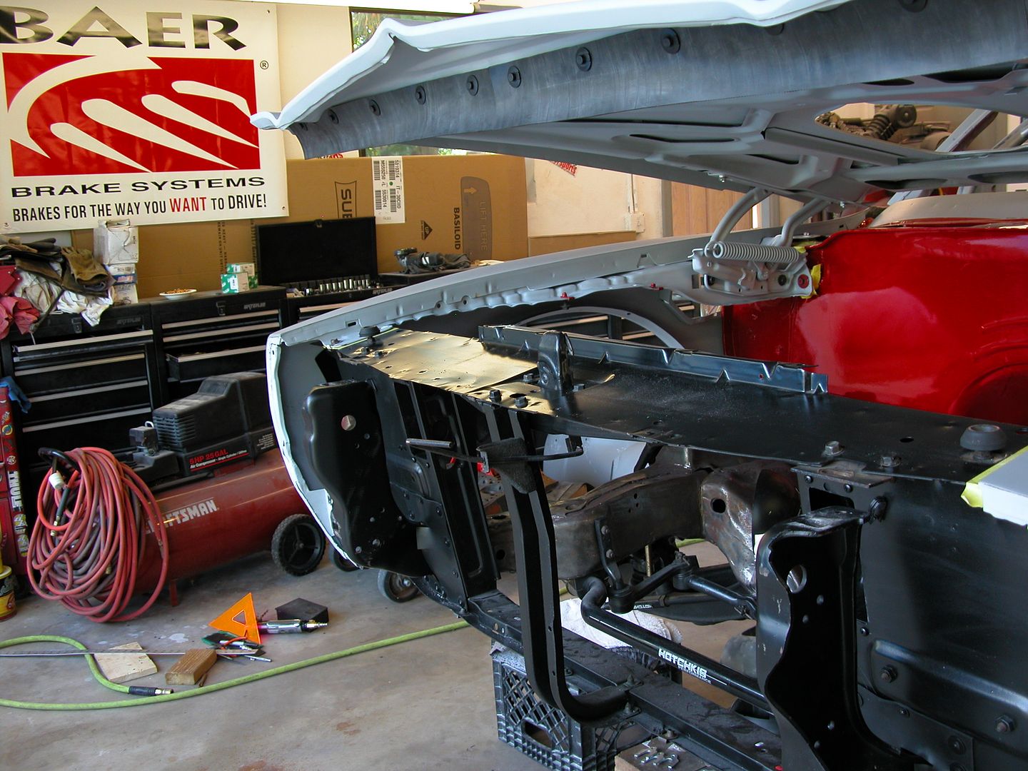 [/URL]
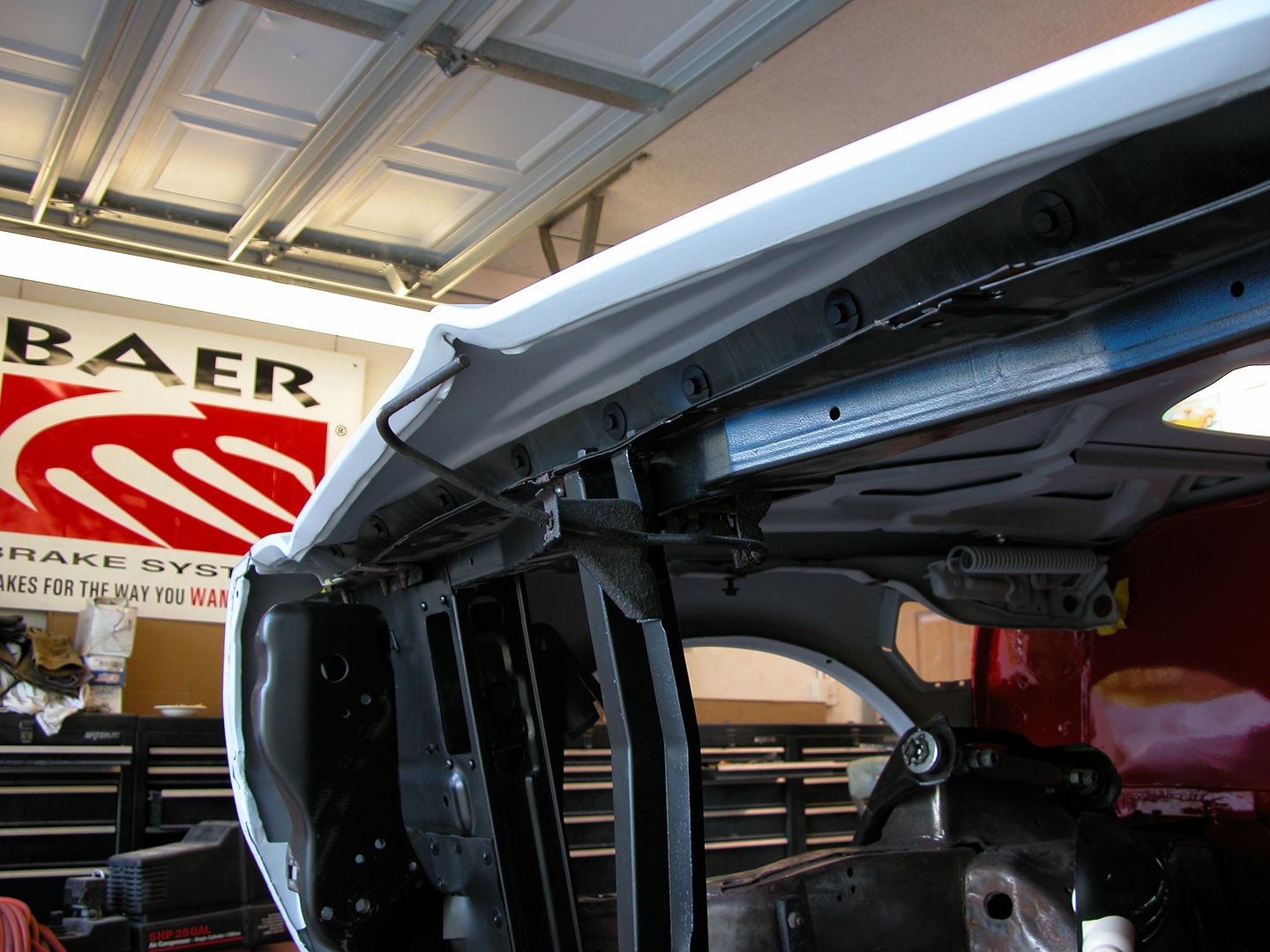 [/URL]


 [/URL]
 [/URL]
 [/URL]

 [/URL]
 [/URL]
 [/URL]
 [/URL]
 [/URL]
 [/URL]
 [/URL]
 [/URL]
 [/URL]
 [/URL]
 [/URL]
 [/URL]
 [/URL]
 [/URL]
 [/URL]
 [/URL]
 [/URL]


