Now that I have this big ans versatile hammer we call an Arduino, everything is starting to look like a nail.
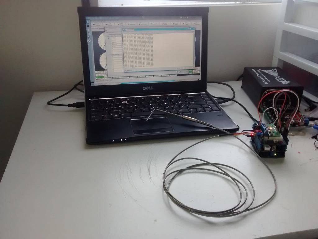
This week I decided to implement EGT sensing. I picked up a Quad MAX31855 thermocouple breakout board for 5V systems (type K) from Ebay. I already had an Arduino Uno, CAN Bus shield from Seeedstudio, and MakerShield from MakerShed with a breadboard adhesived to it from another project. I assembled these and grabbed a K-type EGT probe from Auber Instruments.
The code was easy and I quickly had my Arduino sending EGT and my MS3 receiving it.
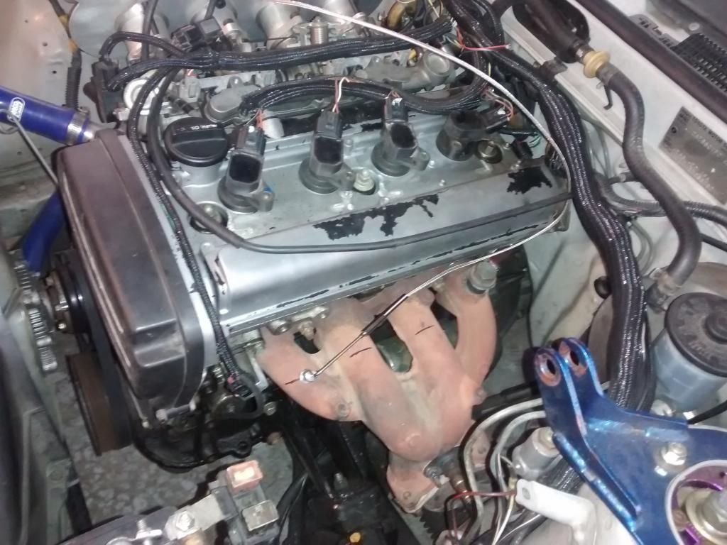
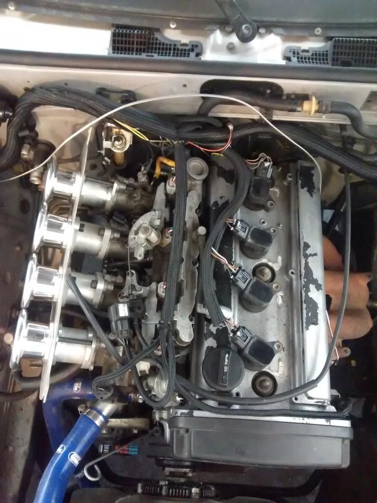
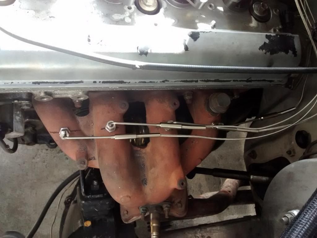
I then went ahead and installed the EGT sensor on my AE86 corolla
I'm confident in this, so I went ahead and ordered 3 more EGT probes, some stripboard, and an enclosure. More to come!
Just out of curiosity, what do you plan on doing the the EGT information?
alfadriver wrote:
Just out of curiosity, what do you plan on doing the the EGT information?
With the 4 EGT sensors I'm going to implement individual cylinder trim.
Looks like your engine setup is somewhat similar to what I'm working on. Is that a Silvertop with the original AE86 exhaust header modified to fit? And are those 1NZ CoPs just plugged onto the spark plugs? I got a set of those myself to run later.
GameboyRMH wrote:
Looks like your engine setup is somewhat similar to what I'm working on. Is that a Silvertop with the original AE86 exhaust header modified to fit? And are those 1NZ CoPs just plugged onto the spark plugs? I got a set of those myself to run later.
Blacktop with silvertop ITBs. 1ZZ coils. I have rails to weld to the valve cover to mount the coils, but had them backwards when I tried the first time. you can see where they were. Just need to reweld them.
burdickjp wrote:
alfadriver wrote:
Just out of curiosity, what do you plan on doing the the EGT information?
With the 4 EGT sensors I'm going to implement individual cylinder trim.
Kind of a rough trimming system, seems.
Plus, the gas temps are very confounded by the spark timing- you'll see a change from cyl to cyl if the spark isn't right, too.
Especially for a port throttled set up like that- what is the temp difference cause by: 1) different airflow due to throttle imalance but injecting the same fuel, 2) different fuel flow, 3) different delta from MBT spark due to a 1 and 2, or 4) all of the above and then some? Lots of things go into exhaust temps, not just combusted a/f. Where as an O2 sensor is just measuring a/f.
good luck with it.
Thermocouples came in and got installed.
I dropped the Arduino stack into my "universal enclosure"
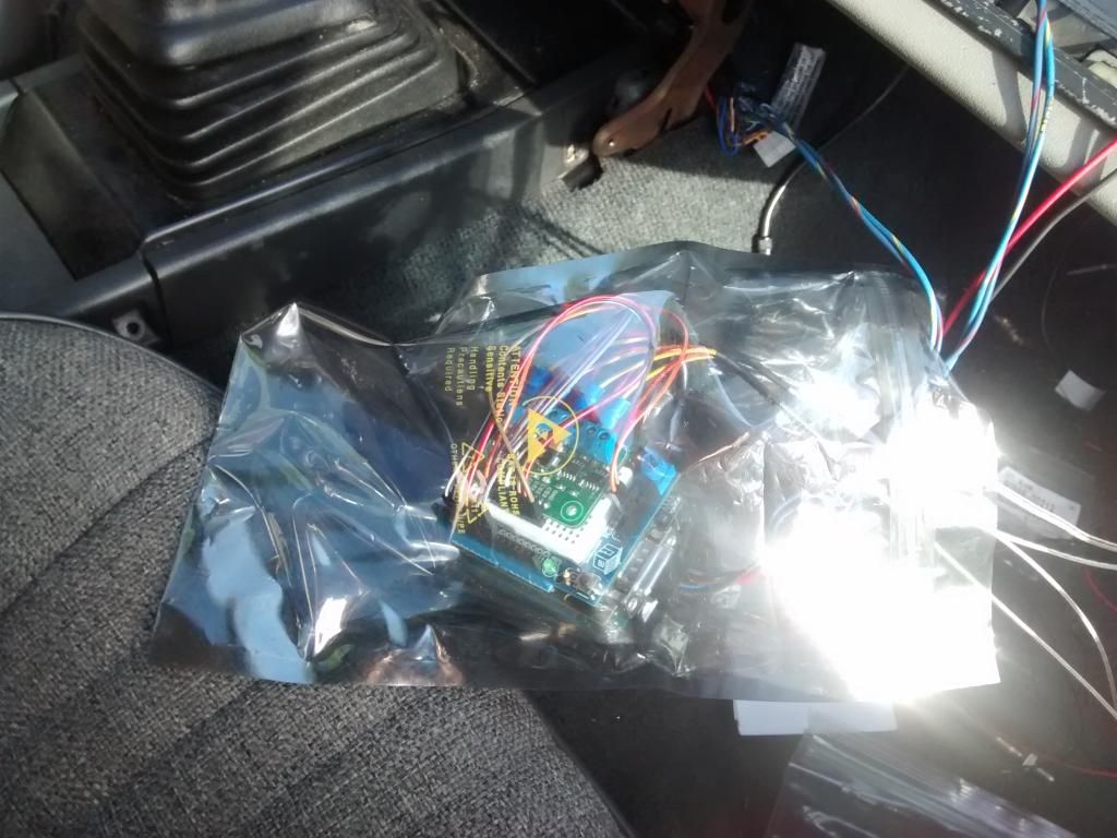
Now I've got 4 EGT logging!
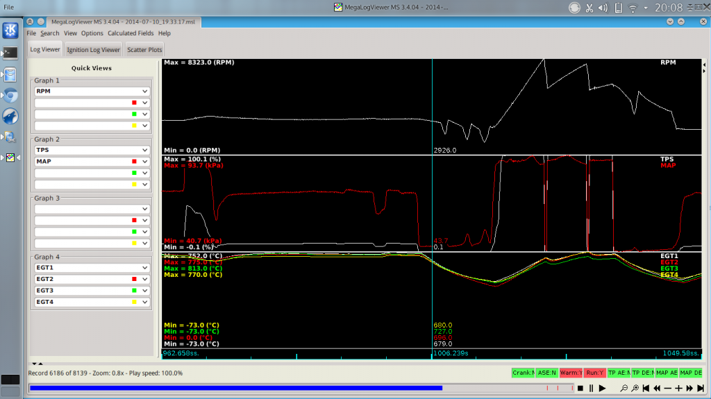
Seems to work reasonably well, but I haven't gotten to play with it TOO much.
Pretty cool. I'm surprised how close they are actually.
I agree with what was said above about it not being practical to predict fuel trim but it's a good sign they are so close. It likely means that air flow, fuel flow, timing etc are all pretty even among cyls.
This is a relatively modern motor as far as combustion chamber and port design goes. They flow rather regularly from cylinder to cylinder.
My next goal is to balance as much as I can from cylinder to cylinder and/or averaging from what I have. To begin with I will balance ITBs

russian
New Reader
7/13/14 5:20 a.m.
You should publish the source code somewhere, it's a cool project :)
Thank you for sharing the information! I have gone ahead an ordered the thermocouple board. Will have a crack at the code since I like to get to know the CAN code for MS. It would be nice if you could share the code you have as well!
Cheers.
Here's the sketch:
http://pastebin.com/C3Gepk0g
I'm using MS3 1.4 Alpha 3, as that has the necessary CAN stuffs. The prior CAN stuffs has a WHOLE LOT more overhead, but people have figured it out with Arduino (obviously). I think for MS2 it requires MS2Extra 3.4 Alpha 1 or later for the same reason.

bcrx7
New Reader
8/15/14 6:35 p.m.
Awesome, THANKS! I am running MS3 1.4 as well!
bcrx7
New Reader
8/18/14 6:12 p.m.
Don't want to bug you too much, but I can't really wrap my head around that code. Is that the code you have been running on your system?
I though the MS is the master unit (id 0), but this code: CAN.sendMsgBuf(0x00, 0, 8, stmp); sends the CAN msg from id 0 (0x00) which is the CAN-BUS Shield. Am I just totally out of the park with this one?
This is my first work with CAN and just don't want to start heading down the wrong road!
bcrx7 wrote:
Don't want to bug you too much, but I can't really wrap my head around that code. Is that the code you have been running on your system?
I though the MS is the master unit (id 0), but this code: CAN.sendMsgBuf(0x00, 0, 8, stmp); sends the CAN msg from id 0 (0x00) which is the CAN-BUS Shield. Am I just totally out of the park with this one?
This is my first work with CAN and just don't want to start heading down the wrong road!
This does not use the old Megasquirt CAN bus protocol. It uses new code implemented in the mentioned firmware. This code was originally implemented to interface with dash loggers.
As I understand it, Megasquirt's old CAN bus implementation was very much not standard, making it difficult for other CAN devices to interface with it. This new code is more standard and easier to inteface with.
bcrx7
New Reader
8/19/14 12:19 p.m.
I have been using that latest code with a digital dash, but didn't realize it was that simplified! Thanks for sharing that! I was looking at all the id's and so on from the previous code's CAN and was already getting confused.
I've been looking all over the web for a how-to on this and I didn't know it would be that easy? But I have to ask, did you do any cutting or soldering to the CanBus Shield? I have the same one and the Seeedstudio CanBus Shield wiki page says something about cutting and soldering some pins.. I wanna make sure before i even connect this to the megasquirt, don't wanna short anything out.
Joeldc510 wrote:
I've been looking all over the web for a how-to on this and I didn't know it would be that easy? But I have to ask, did you do any cutting or soldering to the CanBus Shield? I have the same one and the Seeedstudio CanBus Shield wiki page says something about cutting and soldering some pins.. I wanna make sure before i even connect this to the megasquirt, don't wanna short anything out.
Nope. Ran it just like it came.
For my digital dash and rebuilt the CAN circuitry from scratch, I did a mash-up between the SeeedStudio board and a couple of other schematics. It ends up there's a couple ways of doing it with the same hardware, so I don't think you'll screw it up too much.

NOHOME
SuperDork
12/24/14 6:29 a.m.
Quick question. How do you go about calibrating the temp signal? Are you just using the sensitivity spec of the thermocouple? I am going to guess that temp accuracy is not that critical anyways as long as they are matching cylinder to cylinder?
NOHOME wrote:
Quick question. How do you go about calibrating the temp signal? Are you just using the sensitivity spec of the thermocouple? I am going to guess that temp accuracy is not that critical anyways as long as they are matching cylinder to cylinder?
In what regard? K-type thermocouples produce a predictable microvoltage for a given temperature. These claim to be accurate within a rather narrow range, much narrower than acceptable cylinder to cylinder temperature differences. When sitting ambient they're very close. When gripped in a fist they rise together closely.
Maybe I should boil some water ...
NOHOME
SuperDork
12/24/14 7:30 a.m.
burdickjp wrote:
NOHOME wrote:
Quick question. How do you go about calibrating the temp signal? Are you just using the sensitivity spec of the thermocouple? I am going to guess that temp accuracy is not that critical anyways as long as they are matching cylinder to cylinder?
In what regard? K-type thermocouples produce a predictable microvoltage for a given temperature. These claim to be accurate within a rather narrow range, much narrower than acceptable cylinder to cylinder temperature differences. When sitting ambient they're very close. When gripped in a fist they rise together closely.
Maybe I should boil some water ...
I figured you were using the output spec for the slope determination. Should be close enough. I live in a world where everything has to be verified with NIST traceable calibrators, so tend to go overboard.
Is there an absolute EGT that you want to see or is it more about matching the cylinders? My only experience with EGT is when I use a handheld IR thermometer to find dead cylinders by pointing at the exhaust outlet.
I read the title, and I was all like "post things in English man!"
burdickjp wrote:
...
In what regard? K-type thermocouples produce a predictable microvoltage for a given temperature.
...
Yeah, the voltage/degree is an inherent physical attribute of the two metals used in the thermocouple.
There might be some deviation created by the interface electronics, especially if it uses an individual IC per channel.
I have been researching a lot and finally have my hands on a Megasquirt 3 w/ the MS3X expansion and connected to an Arduino UNO w/ the CAN Bus shield from Seeedstudio as well and have been trying to configure the CAN Receiving window on Tunerstudio to be able to receive the CAN messages but I'm a bit lost.. I don't know what exactly to put on the offset and size tabs. Can you help me out? Thanks in advance!


