burdickjp
burdickjp New Reader
6/17/14 9:54 p.m.

So the gauge cluster in my Corolla no longer agrees with the engine I put in it. The tach only goes to 8k and is incompatible with COP ignition, and the speedo is cable driven. I decided I wanted a new cluster.

My first intention was to use an S2000 cluster. Picked one up on ebay, bought connectors and pins, and started looking at what would be involved in mounting it and driving it. There's a company called JSP Fab who makes a mounting bezel, but it puts I'm not happy with it. Driving it would involve something like an Arduino to convert inputs into something the cluster can talk to. After some soul searching I decided to build my own dash with the arduino and some displays.

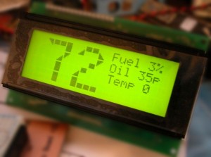
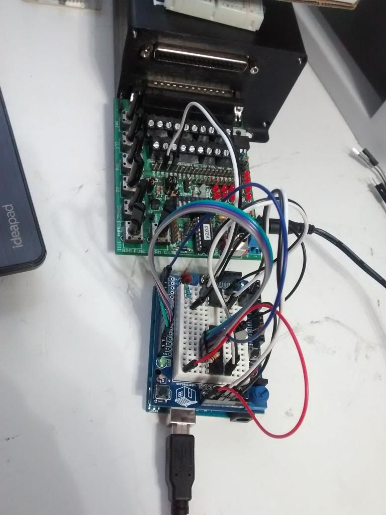
A few days later, here's a functioning prototype:

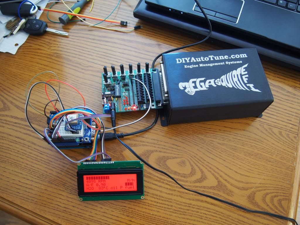
The wirey thing on the left is an arduino uno with two shields on top of it. You can kinda see that it's a stack of three PCBs. The middle shield is a CAN Bus shield from Seeedstudio and on top of it is a MakerShield from MakerShed with a breadboard adhesived to it. On top of the breadboard is an Adafruit Ultimate GPS brekout board. It is what I'm using to read my speed. The display is a RGB backlight positive 20x4 character display. Right now the assembly is being driven by my Megasquirt 3 hooked up to a JimStim. The Arduino talks to the Megasquirt via CAN Bus, which means there are only two wires connecting the arduino to the Megasquirt. Any data the Megasquirt sees or generates can be sent over CAN Bus and read by the Arduino. Right now it is reading RPM, lambda (air to fuel ratio), and water temperature. The GPS sends the Arduino position and speed information over a two wire serial connection. It takes it a bit to get a fix, so I'll probably be putting in a battery backup for the GPS unit and also getting a digital speed sensor for the transmission. Fuel level comes from the regular fuel sender. If I ever have to open up the fuel tank I'll try to install a strip level sensor.

The screen is about 3 in long and 1 in tall. Right now the bar at the top is RPM, with 0 on the left and redline on the far right. Below that on the left is a numerical RPM read out. On the right is speed. There's nothing there until it starts moving, so it's blank right now. Below that is lambda, next to it is a bar read out for oil pressure and then fuel level. At the bottom is water temperature.

I'm thinking about having a larger screen for the tach and speedo only. It would be a 40x4, so it would be the same screen, only twice as long. The current screen would then be only for ancillary information. I'm also thinking of switching to a full LCD.

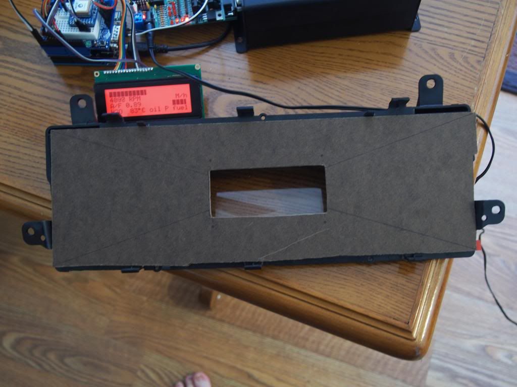
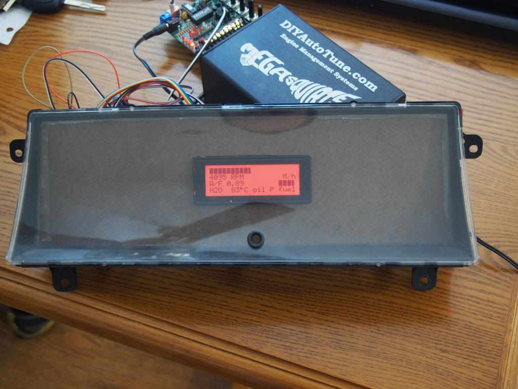
To temporarily mount the screen I grabbed a piece of masonite, pulled the bezel off the original gauge cluster, and used some double-sided tape.

I need to put some warning and indicator lights. I would like lights which have the proper symbols. I saw a bunch which would work well from UK vendors like these. I'm curious if anyone has found anything here in the US which would work.

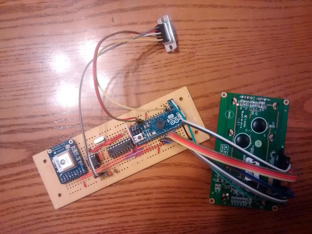
The next step for me will be smooshing all of that Arduino into a case so I can continue prototyping on the car without risking losing a connection. I ordered DIP sockets and CAN Bus chips. I'm going to pair those with an Arduino Micro. Here are the major components in an enclosure I have on hand. 
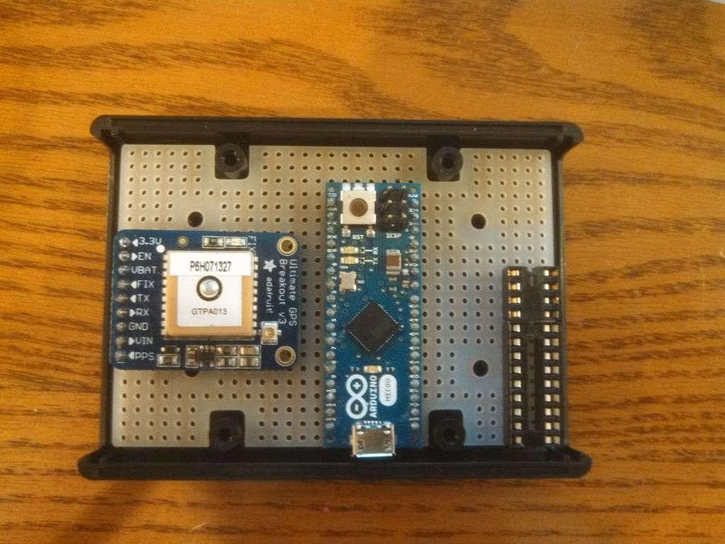
It looks like everything will fit ncicely. I should have room for DB9 or DB15 connectors between the enclosure and the chassis harness and the enclosure and the display.

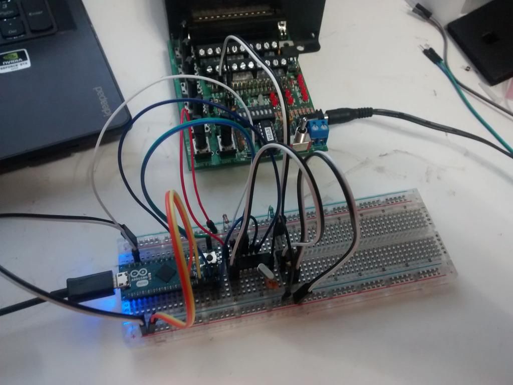
So I went back and started putting my circuit together with the components I'm going to use on a breadboard.

RossD
RossD PowerDork
6/18/14 7:53 a.m.

This is neat!

GameboyRMH
GameboyRMH MegaDork
6/18/14 10:11 a.m.

Nice project! However I'm going to be in a similar situation with a Corolla tach soon, and from what I understand the MS can output a square wave signal (with 1 pulse per rev based on a trigger wheel input) that could drive the stock tach. Did you try this? Just wondering if you found a problem with this approach.

Edit: Here's someone running a setup like what I'm talking about on a 1jz:

http://www.msextra.com/forums/viewtopic.php?f=131&t=48120

Another on an AW11 w/ 4AGE:

http://www.msextra.com/forums/viewtopic.php?f=101&t=45384

Mezzanine
Mezzanine Reader
6/18/14 10:13 a.m.

Great project. I'm in a similar boat where the gauge options available to me leave me dissatisfied. I've considered Arduino, but have no experince with it. More details please, and keep up the good work!

burdickjp
burdickjp New Reader
6/18/14 8:17 p.m.

In reply to GameboyRMH:

I had seen some of the solutions for driving the OEM tach. I was getting annoyed with the cable speedo as well. I also have some future plans for this which go beyond the character display. This is 'version 1' so to speak. I'm trying to follow the philosophy of 'do the simplest thing that will work' and continue iterating in that manner until I have something I'm proud of and happy with.

In reply to Mezzanine:

I had absolutely no experience with an Arduino or C-based languages prior to this project. I had done some work in Python, and was very comfortable in it, but had no formal training in it. That was the extent of my programming knowledge. Two days after starting the project I had it doing basically what I wanted, and two days after that I was rather happy with the code as well. I'd be more than happy to answer any questions, but can't say I'd be as much help as the Arduino forum and existing documentation.

jpnovak
jpnovak Reader
6/18/14 9:13 p.m.

Nice work. Are you polling the serial data packet using the (a,0,6) command?

I made something similar based on the mbed platform.

Mine has a display, 10Hz GPS, accelerometer and SD card datalog.

jpnovak
jpnovak Reader
6/18/14 9:13 p.m.
series8217
series8217 Reader
6/19/14 1:47 a.m.

Very cool! Also very familiar.... Back in 2006 I built the same thing for GM ALDL/OBD I:

burdickjp
burdickjp New Reader
6/19/14 8:20 a.m.
jpnovak wrote: Nice work. Are you polling the serial data packet using the (a,0,6) command?

No. I'm communicating with the megasquirt entirely with CAN Bus. MS3 1.4 has a really slick CAN Bus implementation which makes this a breeze.

series8217 wrote: Very cool! Also very familiar.... Back in 2006 I built the same thing for GM ALDL/OBD I:

Very cool! I'm looking into various large character methods to see how I want to do that when I eventually do.

jpnovak
jpnovak Reader
6/19/14 8:40 a.m.

Cool. My ms2 does not have CAN enabled.

burdickjp
burdickjp New Reader
6/19/14 8:45 a.m.
jpnovak wrote: Cool. My ms2 does not have CAN enabled.

I'm looking at using an Arduino for more I/O for the Megasquirt via CAN Bus.

MadScientistMatt
MadScientistMatt UberDork
6/19/14 9:22 a.m.
jpnovak wrote: Cool. My ms2 does not have CAN enabled.

That just takes two jumpers unless you have one of the very rare green MS2 daughterboards.

burdickjp
burdickjp New Reader
6/19/14 11:15 a.m.
MadScientistMatt wrote:
jpnovak wrote: Cool. My ms2 does not have CAN enabled.
That just takes two jumpers unless you have one of the very rare green MS2 daughterboards.

I had to go back and enable CAN on my MS3. As stated, two jumpers.

KevinGale
KevinGale New Reader
6/19/14 4:51 p.m.

In reply to RossD:

To people asking about an analog tach solution check out this link. I was the one who wrote the code. The solution shown is for a speedo but converting to to a tach would be simple. The code just drives a stepper motor a specific number of degrees based upon the frequency of an input.

http://hillclimb.org/forum/viewtopic.php?f=16&t=1133&p=11148&hilit=Arduino#p11148

burdickjp
burdickjp New Reader
6/19/14 6:33 p.m.
KevinGale wrote: In reply to RossD: To people asking about an analog tach solution check out this link. I was the one who wrote the code. The solution shown is for a speedo but converting to to a tach would be simple. The code just drives a stepper motor a specific number of degrees based upon the frequency of an input. http://hillclimb.org/forum/viewtopic.php?f=16&t=1133&p=11148&hilit=Arduino#p11148

That's awesome and fantastic and would allow me to completely retrofit my OEM cluster if I (or anyone else) so wanted. Especially awesome is finding the stepper motors used in clusters. Thank you very much!

KevinGale
KevinGale New Reader
6/20/14 9:14 a.m.
That's awesome and fantastic and would allow me to completely retrofit my OEM cluster if I (or anyone else) so wanted. Especially awesome is finding the stepper motors used in clusters. Thank you very much!

I'm willing to provide some help with coding issues. Walter (referenced in the hillclimb.org thread) is the hardware guru and will probably be happy to help there. Walter did all that documentation and I commented the code extensively so people could reuse it.

Giant Purple Snorklewacker
Giant Purple Snorklewacker MegaDork
6/20/14 9:19 a.m.

Hey! I did one of those too!

Data logging dash with 3 axis accelerometer. Driven directly from regular gauge senders. This one is not Arduino based - it uses an Atmel 168 and discreet/logic components directly.

Five step programmable fuel gauge that blinks one lap (the programmable part) before it's time to pit. This one uses an Arduino Uno.

chknhwk
chknhwk HalfDork
6/21/14 9:54 p.m.

This is so far above my pay grade it's not even funny. Subscribed because I have no idea what's going on!

burdickjp
burdickjp New Reader
6/26/14 7:03 a.m.

I was having trouble getting CAN Bus to work off the shield, so I went back and put the circuit together on the breadboard shield:

That worked. So I copied the circuit over to the Arduino Micro:

That also worked! Now I'm assembling the rest of the circuit on that breadboard before moving it to the enclosure.

burdickjp
burdickjp New Reader
6/27/14 10:22 p.m.

So it turns out laying out circuits on a perfboard is something I suck at. Even if it's paired pads. I ended up taking a Radioshack Coupon I had and picking up a cheap perfboard which is laid out similar to a breadboard and building my circuit on there. It works, but it isn't pretty, and I don't have an enclosure for it. I'll just attach it to the back of the bezel with some stand offs or something like that.

Either way, there's version 1. Next is adding warning/indicator lights. I still don't have a good solution there. I'll also be rebuilding this circuit on some stripboard in a nice enclosure. I think I'll make some breakout boards for the CAN Bus interface, as it looks like I'll be building a bunch of these. That's something I can have made up on a few PCBs, maybe even sell a few over on the Megasquirt forum.

stefanst
stefanst
6/30/14 1:08 p.m.

Great work!

I have just ordered a CAN bus shield for my Arduino, planning to do essentially the same thing. The only difference is that I want to run my cluster with some of those GM instrument steppers, giving me a fully analog display. Running the steppers is pretty easy, but I'm having trouble wrapping my brain around the Megasquirt implementation of the CAN protocol. Would you mid posting the code you're using for extracting the information from the Megasquirt? Any details like the library used and the Arduino IDE version etc. would also be helpful...

Thanks!

burdickjp
burdickjp New Reader
6/30/14 8:17 p.m.
stefanst wrote: Great work! I have just ordered a CAN bus shield for my Arduino, planning to do essentially the same thing. The only difference is that I want to run my cluster with some of those GM instrument steppers, giving me a fully analog display. Running the steppers is pretty easy, but I'm having trouble wrapping my brain around the Megasquirt implementation of the CAN protocol. Would you mid posting the code you're using for extracting the information from the Megasquirt? Any details like the library used and the Arduino IDE version etc. would also be helpful... Thanks!

It'd be easiest to run one of the newer firmwares which supports CAN broadcasting. I've got an MS3, so I'm running 1.4 http://www.msextra.com/forums/viewtopic.php?f=125&t=53354

It sounds like there's similar code for the MS2. After that it's really freakin' easy.

Here's a paste of my sketch http://pastebin.com/nA34ZM3b

You'll need to log in to post.

Our Preferred Partners
gkeaDXS0YcxCEwXkQd3o7mUjsF6zfT1g8KwlBzHSRe0hZJYYd1hX8dVhM2nyzToM