


In reply to Keith Tanner :
Trippy Needles sounds like a bunch of kids in the 90's heard the Velvet Underground for the first time & decided to start a band. :)
I really like the way this is turning out!

In reply to Keith Tanner :
Trippy Needles sounds like a bunch of kids in the 90's heard the Velvet Underground for the first time & decided to start a band. :)
I really like the way this is turning out!

Progress on the VSS and tach reading, so we're moving along. Lots of interesting possibilities to play with, that's for sure.
Okay, so moving along with my plan of making this a peripheral...
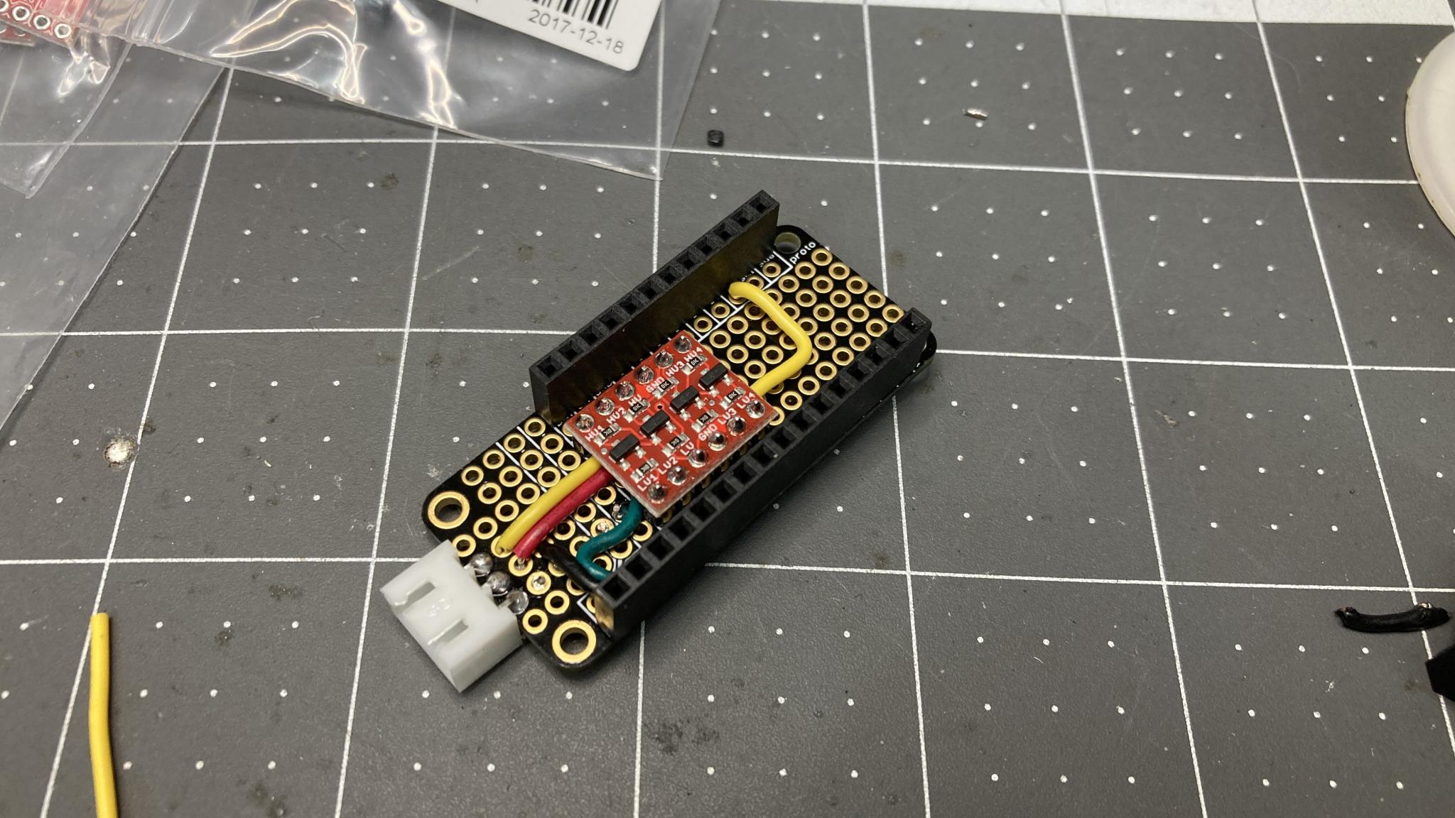
We have the LED ring pretty much nailed, I think. The next step is to come up with a plug-in driver board for it. The LED uses 5V logic but a lot of microcontrollers use 3.3V. So that means a level shifter. Didn't take long to put this together. The level shifting breakout is actually capable of handling four channels but that's all I had :) My prototypes are being made out of easy-to use modular pieces called breakouts, that's one in red. Red means I sourced it from Sparkfun, who happen to be in CO so shipping is super-fast.
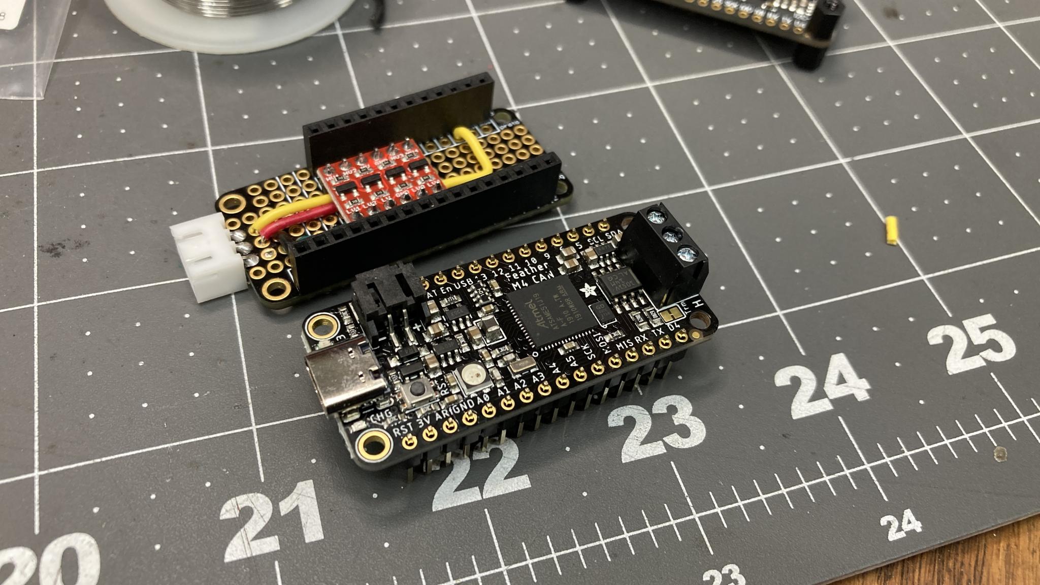
And, uh, if you have a CAN-equipped car this is all you need. An M4 CAN "Feather" from Adafruit ($25 these days), my level shifter board and the LED PCB that's currently installed in the cluster. That's the same microcontroller that's running everything in my current cluster. It literally plugs into my level shifting extension board, which is what Adafruit calls a "FeatherWing".
Sweet. But the goal is to have this thing read the signals coming into to a stock cluster. So I spent some time finalizing my inputs and outputs. I ended up with 4 analog 0-12v inputs (dash lighting, coolant gauge, fuel gauge, oil pressure for example), 2 digital 12v (ie, the tach) and 2 digital 5V (vehicle speed). The 0-12v analog inputs are actually more like 0-15v just in case the alternator gets a little excited.
Only 4 analog inputs? That's the limit on the RP2040 Feather I'm using for testing. With the standard Stemma QT connector on the Feather, I can add more inputs with little daughter boards but this will work. AFR and boost level are the most common requests, and it looks like the standard GM 3 bar MAP sensor has a 0-5V output while most widebands have a 0-5V. One $10 ADC (analog to digital converter) that handles 4 channels up to 5V, plug it in and voila.
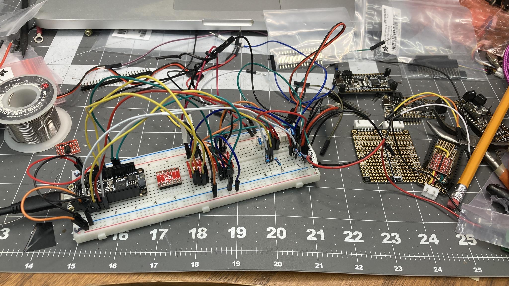
Time to use the breadboard for a gut check. This always looks like mayhem. But we've got three voltage levels (3.3V, 5V, 12V), 8 inputs, a couple of outputs and other random stuff going on.
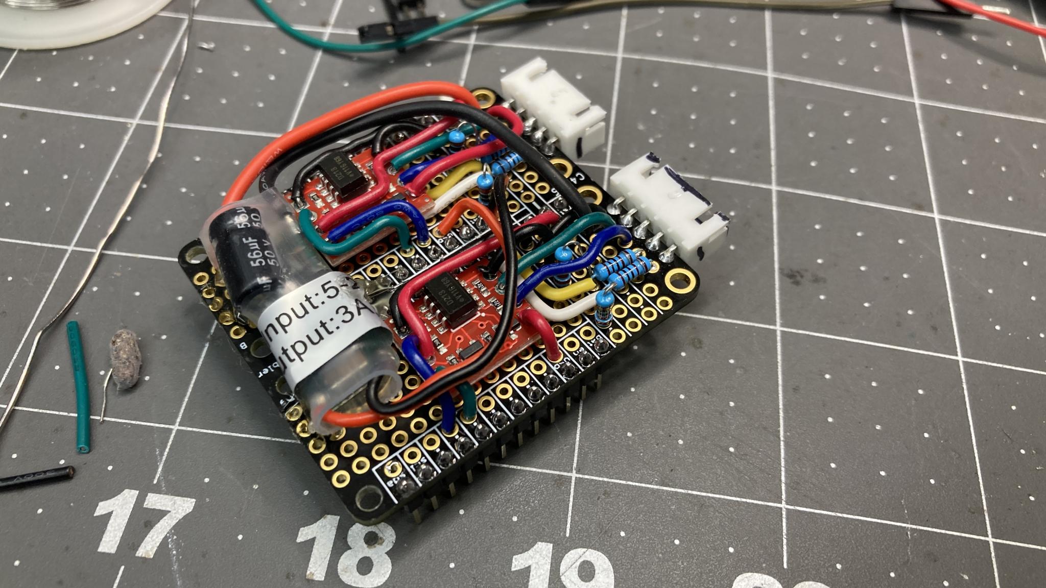
For the prototype, I had to go with a double-wide Wing footprint in order to fit everything in. That's the penalty for using nice neat breakouts. I spent some time paying attention to wire routing as a reaction to looking at the breadboard :)
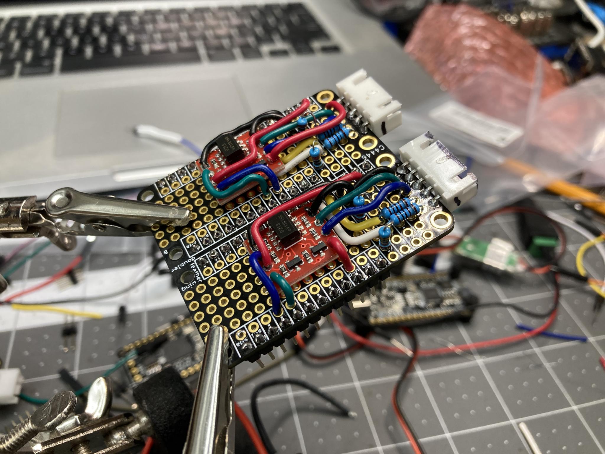
And voila, all complete including an onboard voltage converter that provides enough 5V juice to feed the LED array at full blast. I managed to get everything into the footprint which is yay.
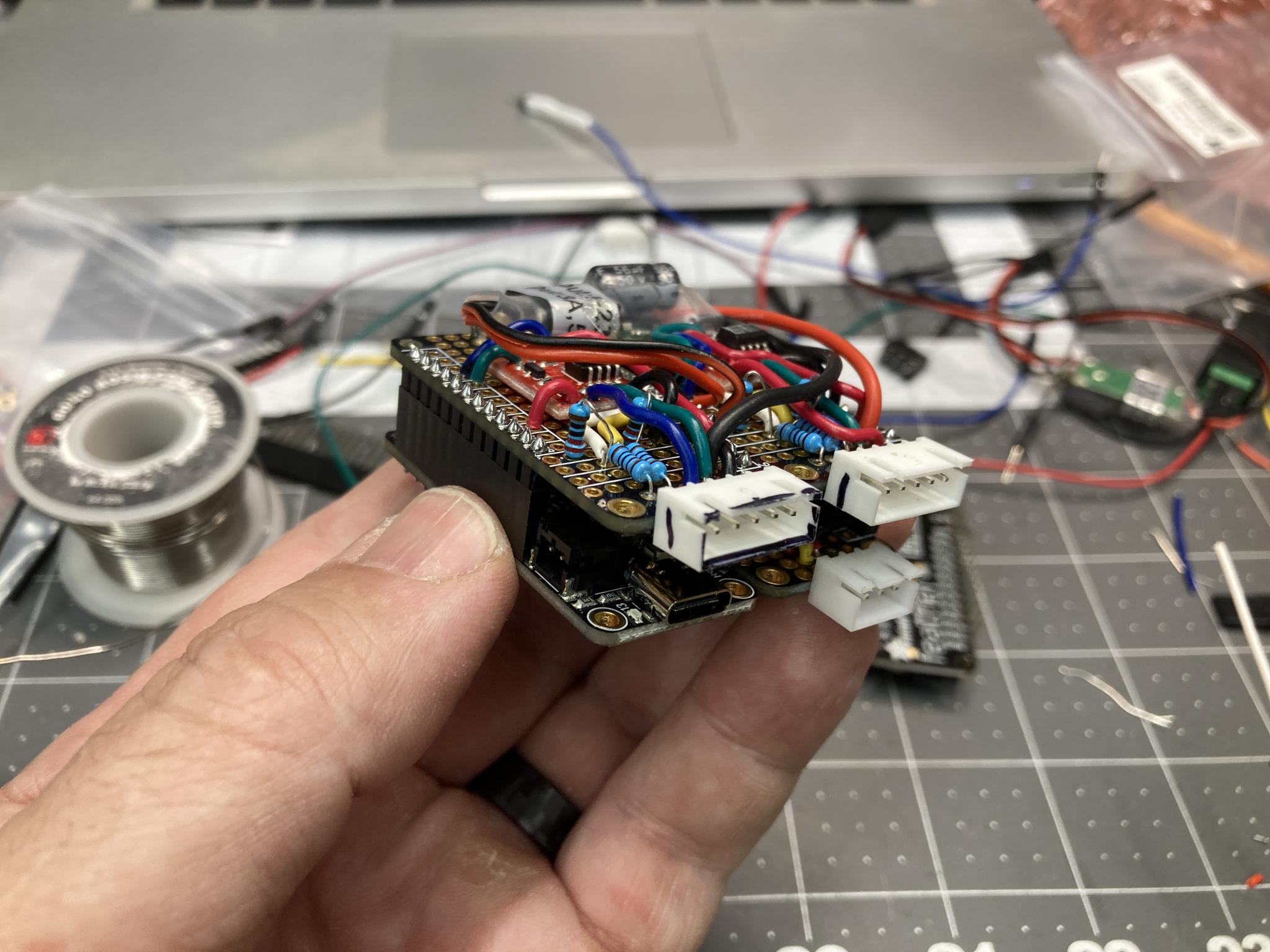
All assembled with a Feather (a $12 RP2040 unit because we don't need CAN), the level shifting Wing and the I/O double Wing. This should be everything I need to run a single LED ring like in the previous demo. If I wanted to run two (one behind the tach and one behind the speedo), I'd have to watch my power consumption. Each of those clusters can pull almost 3A. I never came close in my demo, probably less than half that.
Cute little thing. Not bad for a hand-soldered prototype. If I wanted to add control of the two needles, I could simply plug in a $20 motor control board. That's what I did on my own dash.
Next step is to actually hook it up to a cluster and make sure it works. It's all good on the bench so far, but you know how that goes.
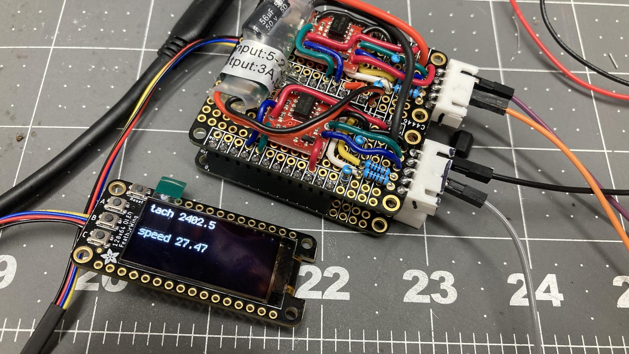
A couple more bench tests to make sure it's working the way I think it should. Here it is living with nothing more than 12v, ground, VSS and tach. The screen is plugged in temporarily to make it easy to ensure everything is working, but it does a good job of illustrating the modular nature of what we're working with.
Next step is to turn those hand-built prototypes into proper circuit boards. I'm starting to learn how to use KiCAD, which is a whole new adventure!
Heads up for those who are interested - I'm doing another video on the progress, mostly because I'm scheduled to do a video and I'm more excited about this than anything else I'm working on. Besides, it has blinky lights and cool pieces of equipment.
If you want to watch it live, tune in to Flyin' Miata's Facebook page at 2:00 PM Mountain on Thursday and you can ask questions in real time. We'll post it to YouTube the next day and I'll link it here.

Keith Tanner said:Heads up for those who are interested - I'm doing another video on the progress, mostly because I'm scheduled to do a video and I'm more excited about this than anything else I'm working on. Besides, it has blinky lights and cool pieces of equipment.
If you want to watch it live, tune in to Flyin' Miata's Facebook page at 2:00 PM Mountain on Thursday and you can ask questions in real time. We'll post it to YouTube the next day and I'll link it here.
In for the blinky lights.

I'll have to take another look. The Dart's speedometer is not working (come to think of it, neither is the fuel gauge or ammeter, although the last one is bypassed due to wiring mods), and I'm considering replacing the needle with a LED sweep at this point.

I hope this hasn't been brought up but our own Calvin Nelson has a digital dash in his Studebaker. But I love the idea of a Chronometric tach. Is this something we can talk Megasquirt into doing for us? Heck I'd pay for that feature.
I have accidentally created the chronometric tach a few times when I've done something with the coding that's overloaded the processor. The refresh rate drops way down and voila, chrono tach :)
It actually would be pretty easy to emulate. My current setup is reading the tach pulses and driving the LEDs in response, but I could easily have it drive the needle as well using the standard air core gauges. Just drop the update time to 500 ms instead of 12.5ms like I'm using and voila. Although IIRC they acted slightly differently going down than up, right?
If you wanted to emulate a chronometric tach from a functional air core one, I can give you a parts list and some code. It'll cost about $25 to buy the parts if memory serves. Might be $35.
Duh, it's not even that hard. I forgot a friend and I were working on that on the side. Watch this space :)
As promised/threatened. Lots of questions (in later FB comments, post-broadcast) about MS2 compatibility, so I guess I need to make a very clear guide on how to get this working with whatever the MS2 CAN implementation is. Matt, help? ;)
In reply to Keith Tanner :
Best bet is to use 11 bit CAN broadcasting. There's also a 29 bit protocol, but it's a bit weird, uses part of the address as an instruction. Here's specs on 11 bit.
http://www.msextra.com/doc/pdf/Megasquirt_CAN_Broadcast.pdf
There is also a third party Arduino library out there that may help.
https://www.msextra.com/forums/viewtopic.php?t=73129&hilit=Arduino
I just needed the message definitions, listening to an 11 bit CAN network is pretty straightforward. Thanks!
Keith Tanner said:I just needed the message definitions, listening to an 11 bit CAN network is pretty straightforward. Thanks!
You're welcome. The end user just needs to make sure 11 bit broadcast mode is turned on in TunerStudio, and stay away from the 29 bit mode if you want to keep your sanity.
Hey, remember this? I've been doing new stuff!
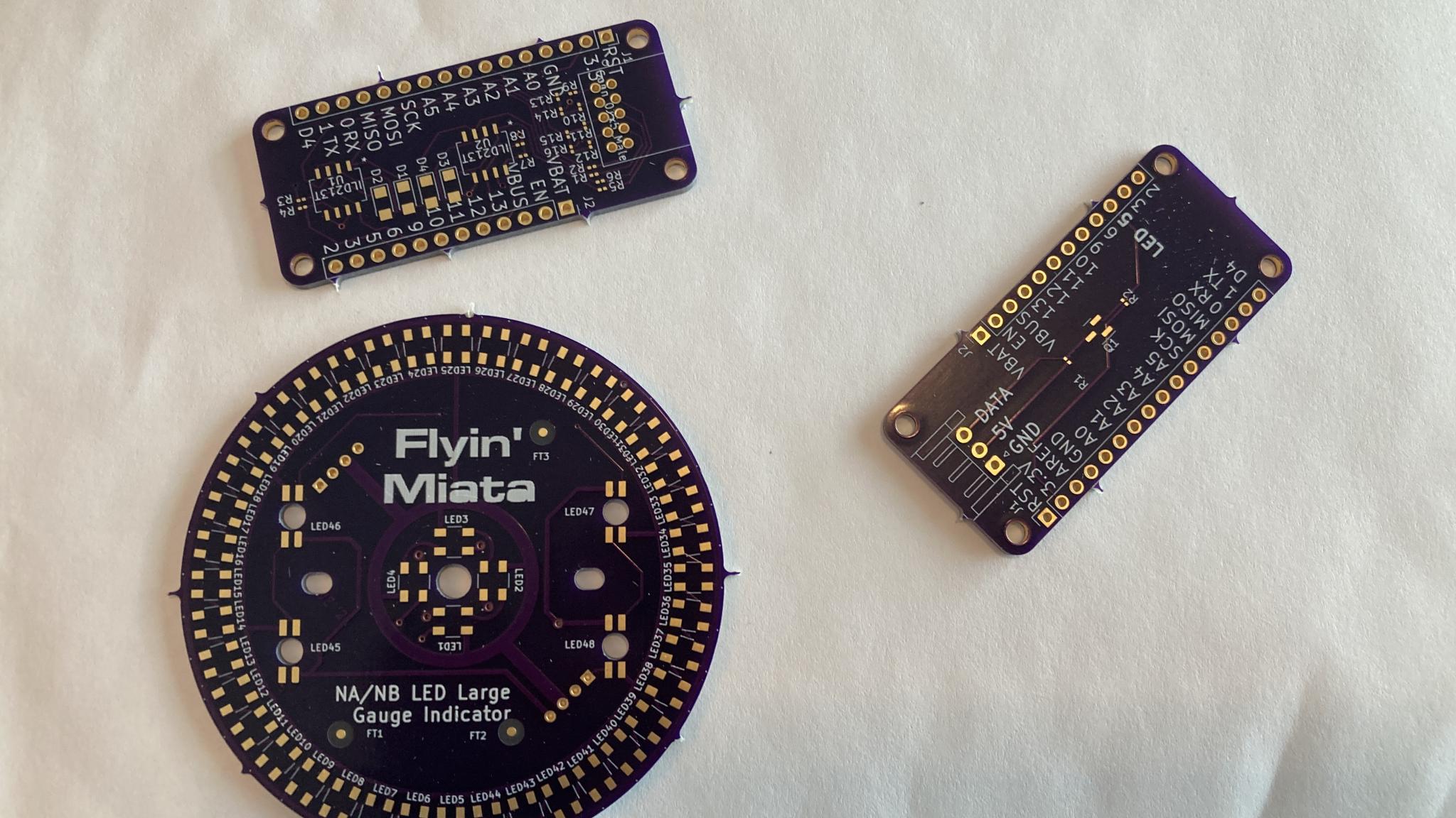
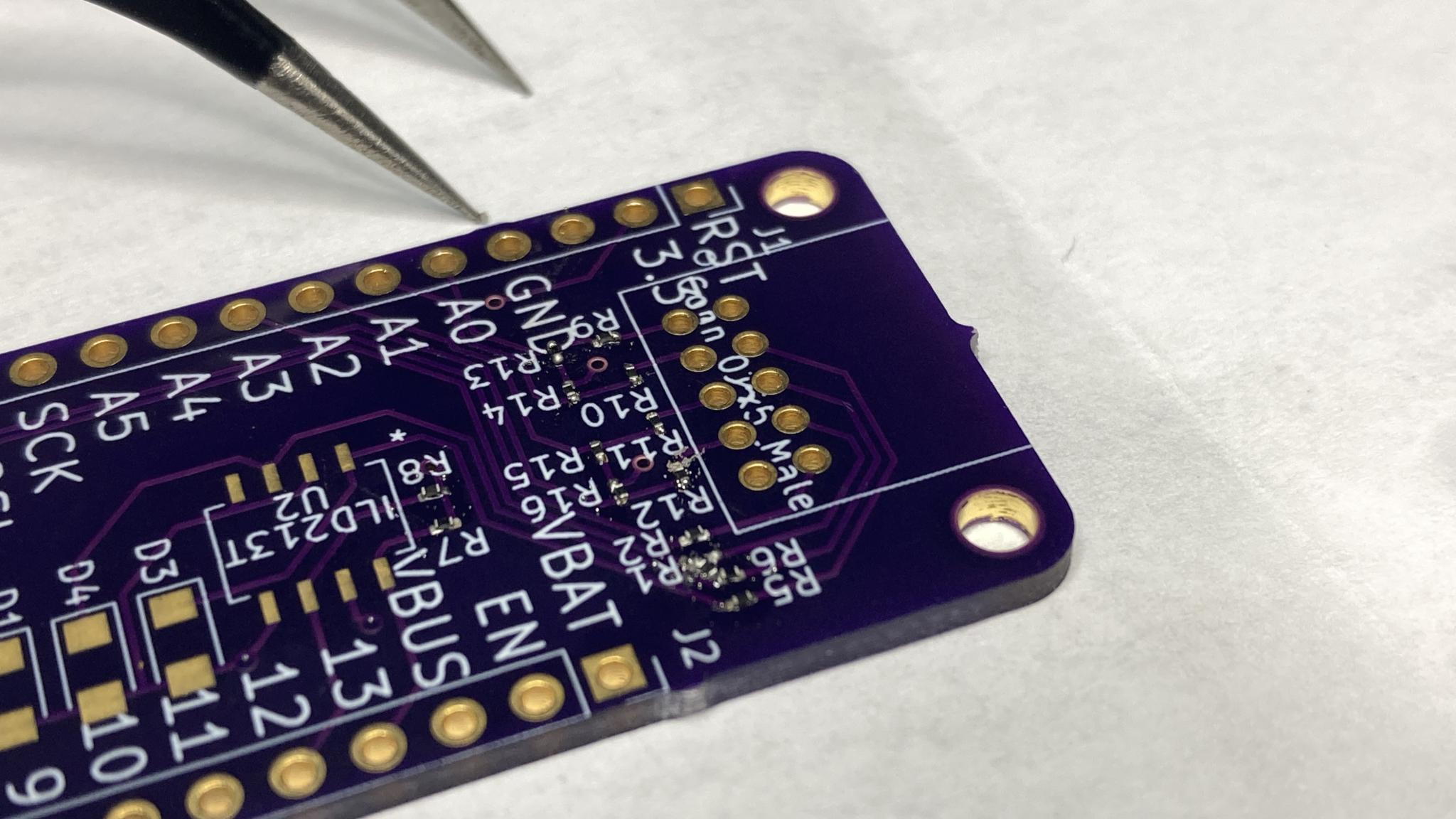
First was learning how to lay out circuit boards, then sending the designs off to OSH Park for fabrication. This was a new thing for me, and they're cheap! $27 for three copies, and I have three designs. So much easier than trying to do it at home - and OSH is the winner when it comes to customer communication. I've never had so many status updates on an order. Opening the envelope was like Christmas, I feel like I've unlocked some sort of nerd achievement level. So cool.
The rectangular ones are my work, the round one was done by the EE we were working with. I've since redrawn it so I can make some tweaks.
Next, I needed to populate them. I've done some fairly complex boards in the past but only using through-hole components and not the sexy new SMT stuff all the kids are using these days. And I very cleverly used the default 2mm resistor size in KiCad. A 2mm resistor is really small. Like, it took me a couple of tries to learn how to get them off the tape without losing them. I'm using solder paste and a hot air gun, which is a new technique for me. So much learning.
Can you see the resistors in place here? This was pretty early in the learning curve, they're all good connections but messy. I started with the resistors so it only got easier, and it's really easy to check function with a multimeter.
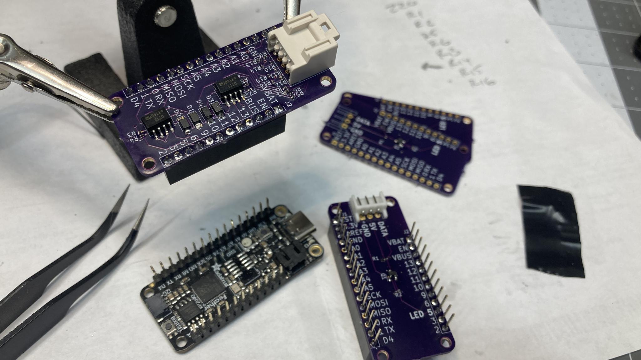
Progress. This is my I/O board, designed to receive the noisy signals from the car and turn them into nice pretty digital.
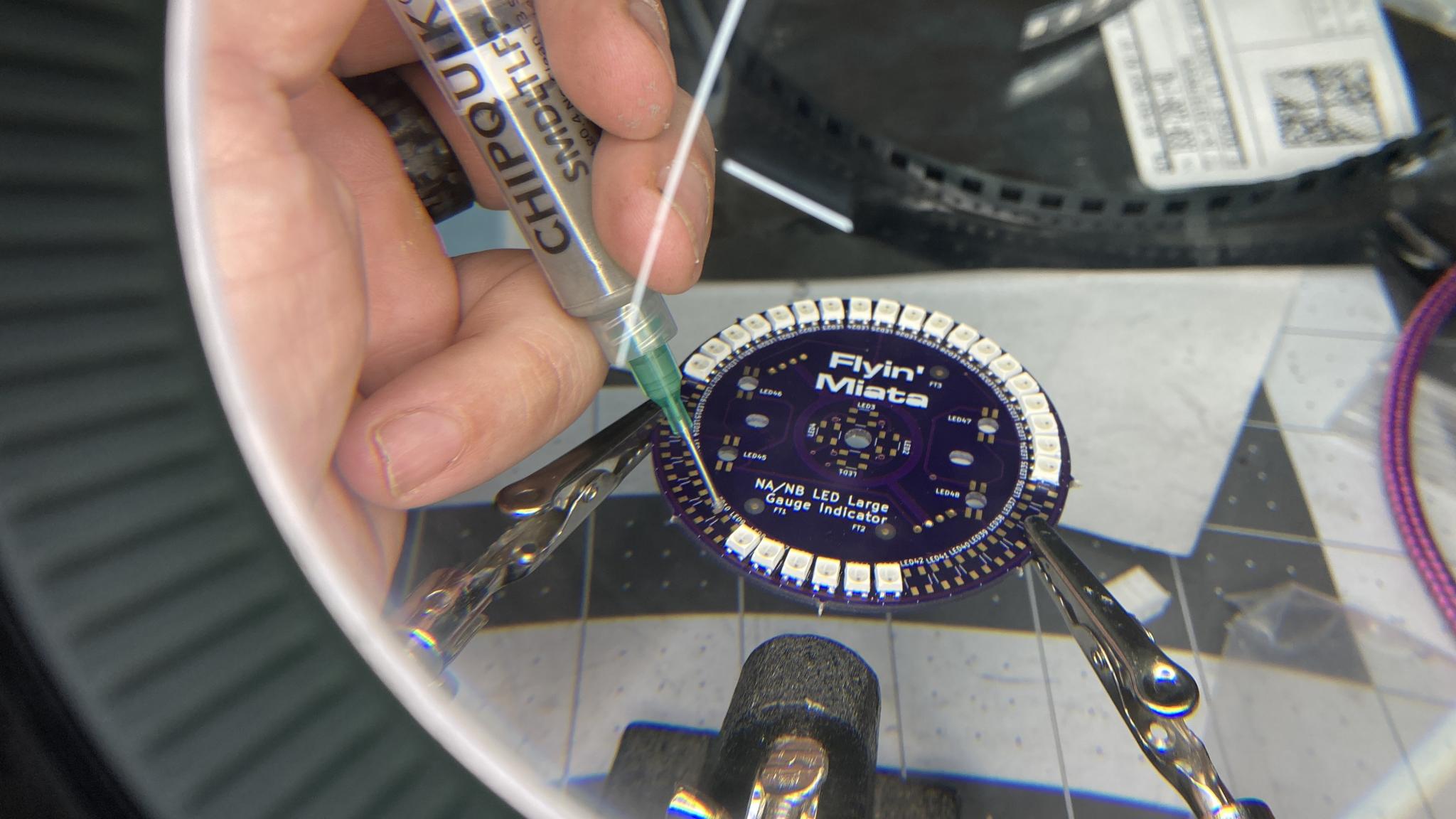
The LED ring was fairly straightforward but has a whole lot of connections that have to be right - 4 per LED with 48 LEDs, and if any one of them is bad it kills the remainder of the chain. The syringe is used to put down the solder paste. It's good practice and I'm getting the technique down.
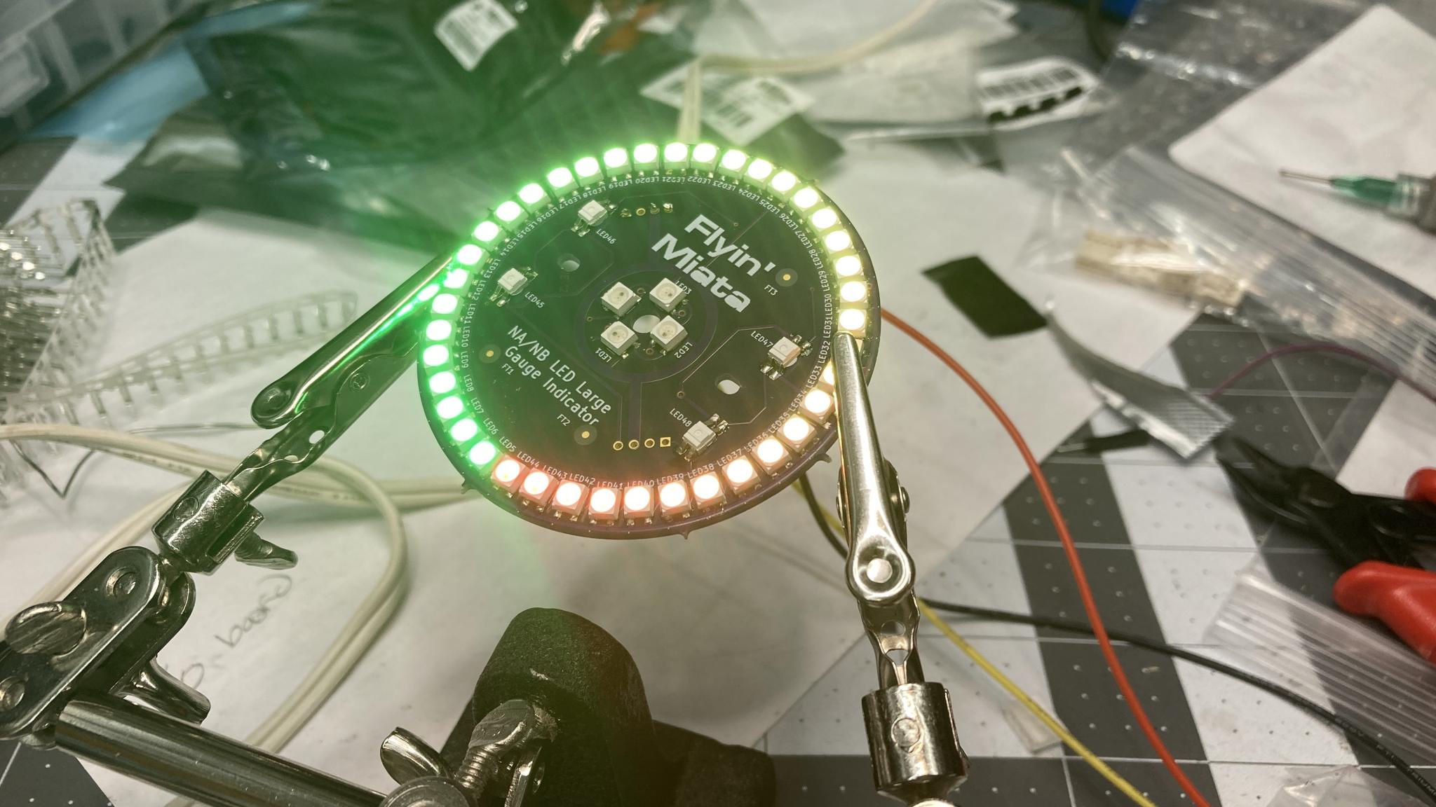
Success!
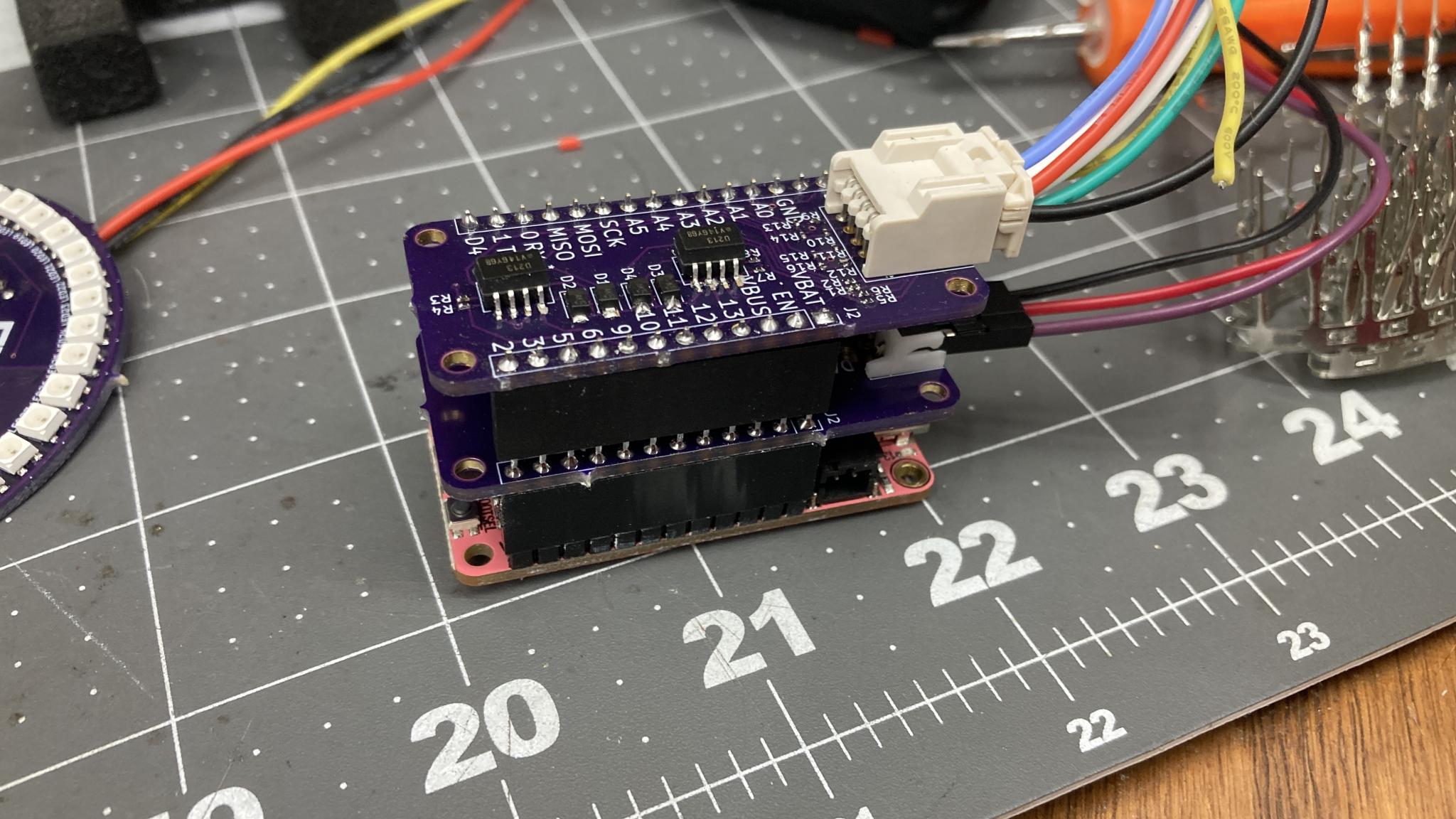
After all that, here's what the full stack looks like. That's the I/O board on top with the big connector - it can take 4 digital channels and 4 analog, with a voltage range of 0-18v for a bit of safety. The one in the middle is the LED driver, the bottom is the microcontroller board. The scale is in inches.
What followed was some gradual testing, making sure the driver could run the LEDs and then testing analog inputs and digital inputs. The circuits should be the same as my original prototypes but between the printed boards and the SMT soldering, success was not a given. But eventually, I got to this.
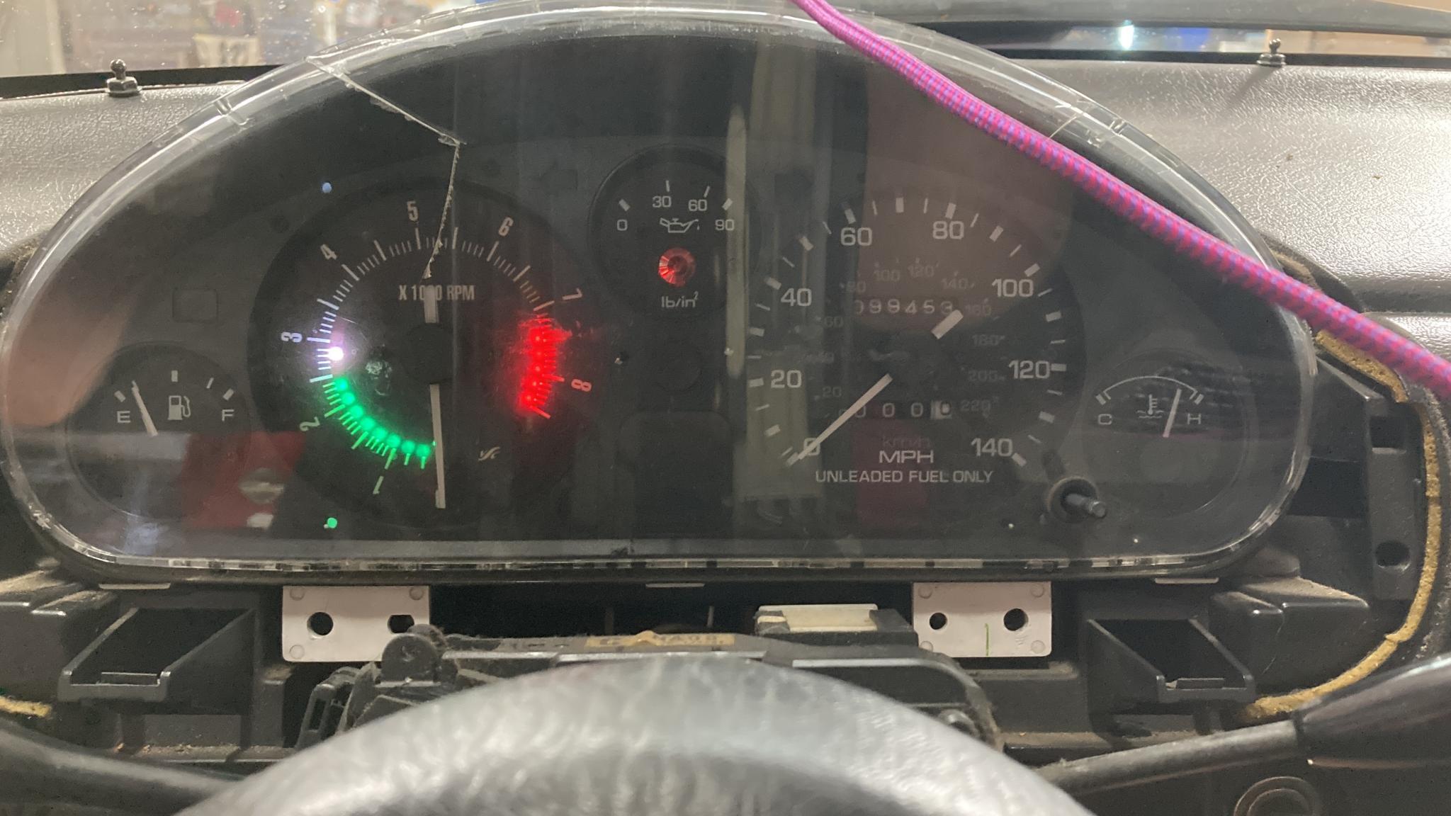
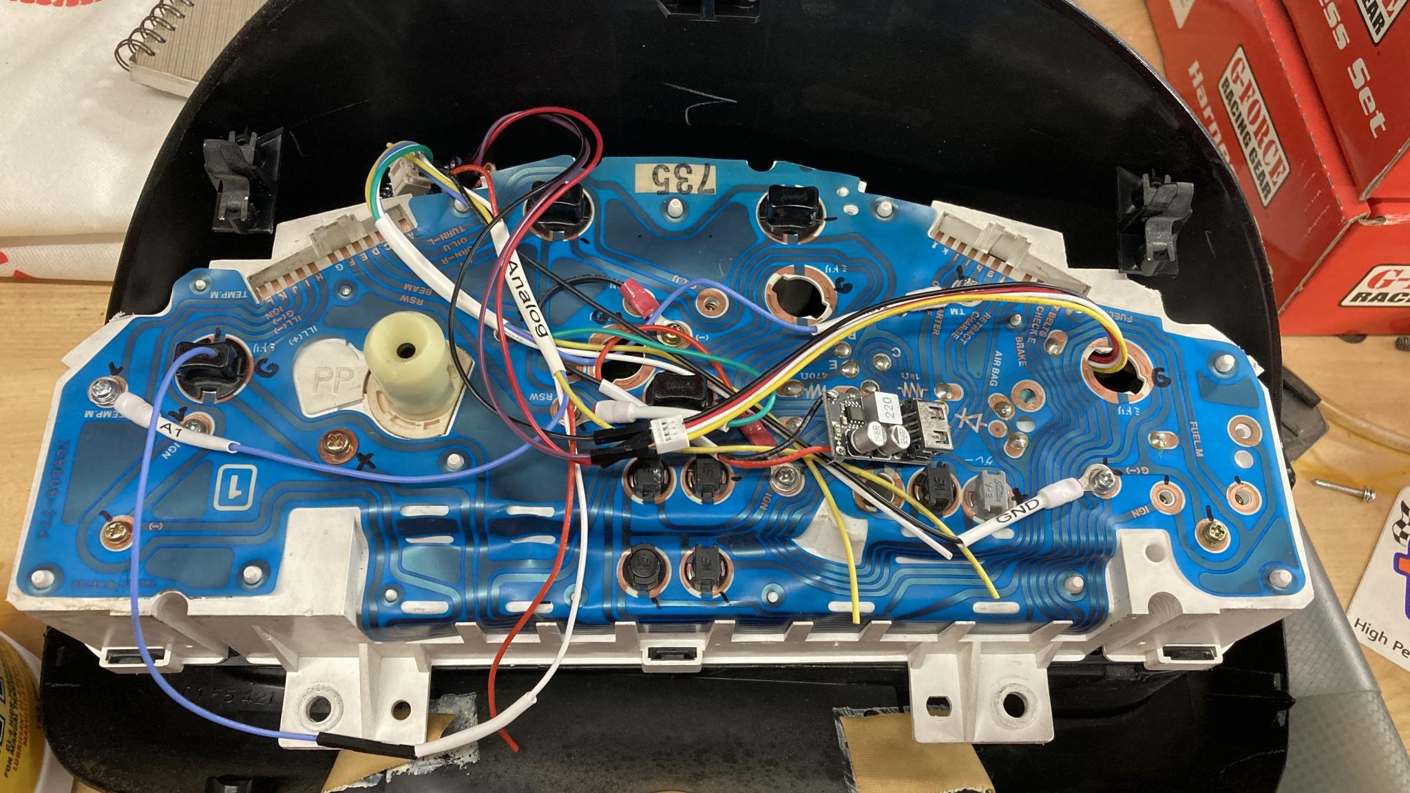
That's something we've seen before. But what makes it very cool is that this is a bone stock 1990 Miata. No cheating with CAN signals or anything, it's reading everything off the back of the cluster - lighting, vehicle speed, tach and coolant temp at the moment. All the connections but one are done with ring terminals. in this picture, the circuit boards are sitting on top of the cluster where there's room for it to tuck under the cover. It looks a little messy but there are only four connections - there's also a USB power supply tapped in there that's not currently being used.
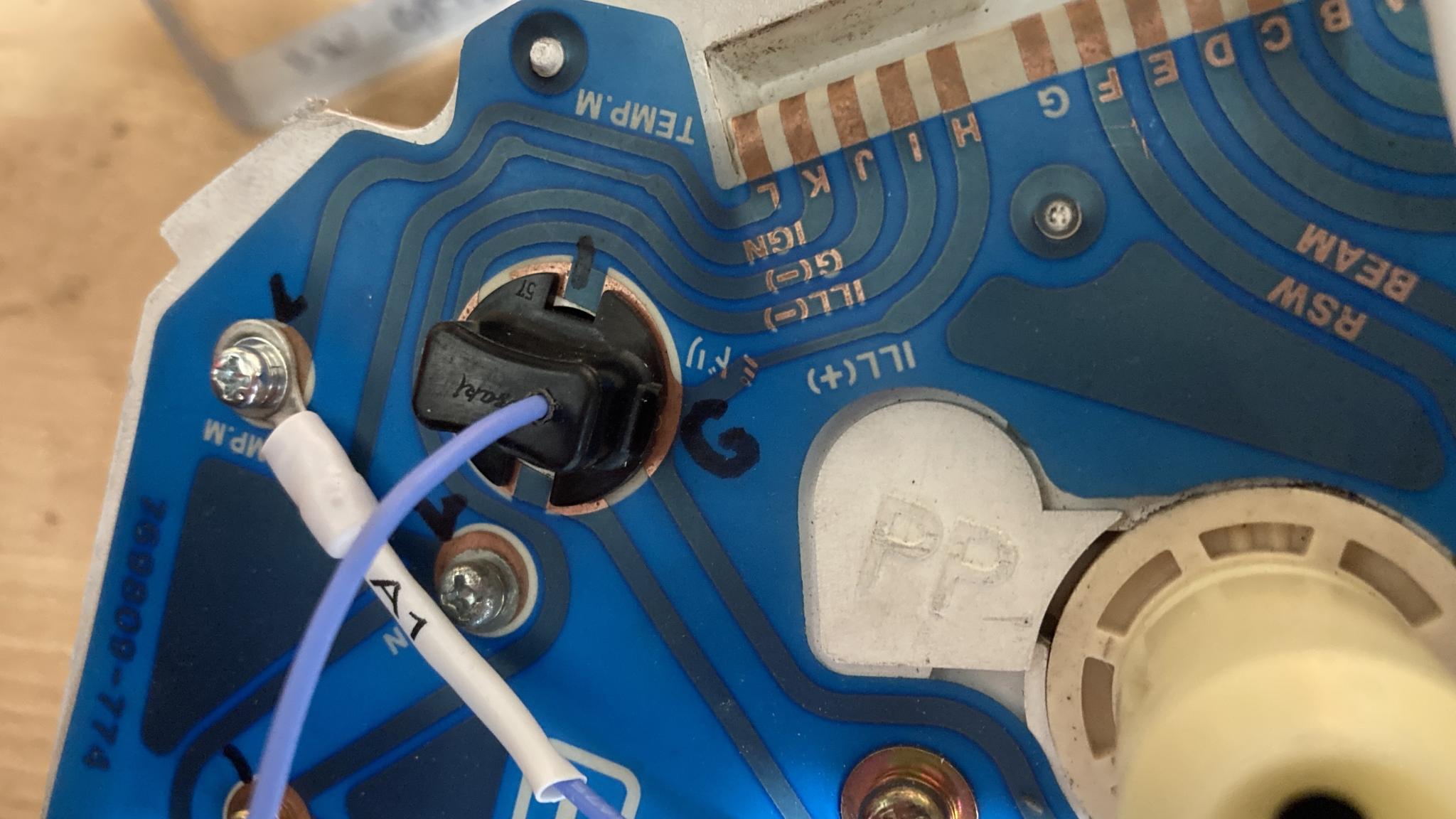
Here's the one connection that wasn't done with a ring terminal. I needed a way to tap into the lights so I can dim the LEDs when needed. I modified a lightbulb holder.
Wooo! Big progress here. It's not perfect - I'm seeing some glitching in the tach readings so I need to fix that up, and the tach needle went dead when I hooked this up so I think there's a diode required here - interestingly, that didn't happen on the bench. I also need to finalize some details like connector types. A set of "real" gauges are being designed by Adam at Revlimiter - I sent him an LED ring and a little controller that will just perform a repeating demo so he can confirm they work before he sends them to me. Watch this space!

Wow. Again, very impressive. It's cool to see this progressing along.
So, this is not a dead project. I've been through a couple of revisions of the boards. One of them was to make the tach needle work properly, the others were to make them easier to produce. I also beefed up the backlighting. Adam hasn't had the chance to get the gauges done yet, because apparently there's quite a science to the masking on the back to avoid hot spots - not all aftermarket gauge faces have this level of attention to detail, but Adam is wired to do the best possible job. I'll have the final final FINAL (1) versions of the boards in hand in the next couple of days, then I'll be putting a few clusters in staff Miatas at FM for road testing and more user input.
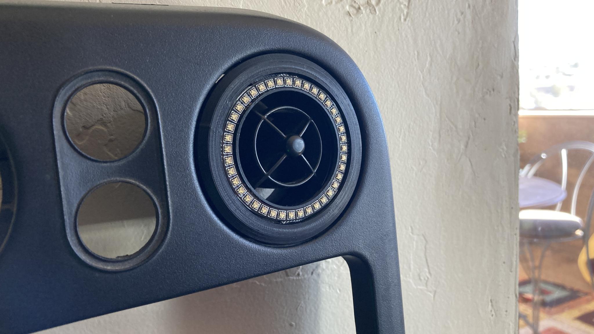
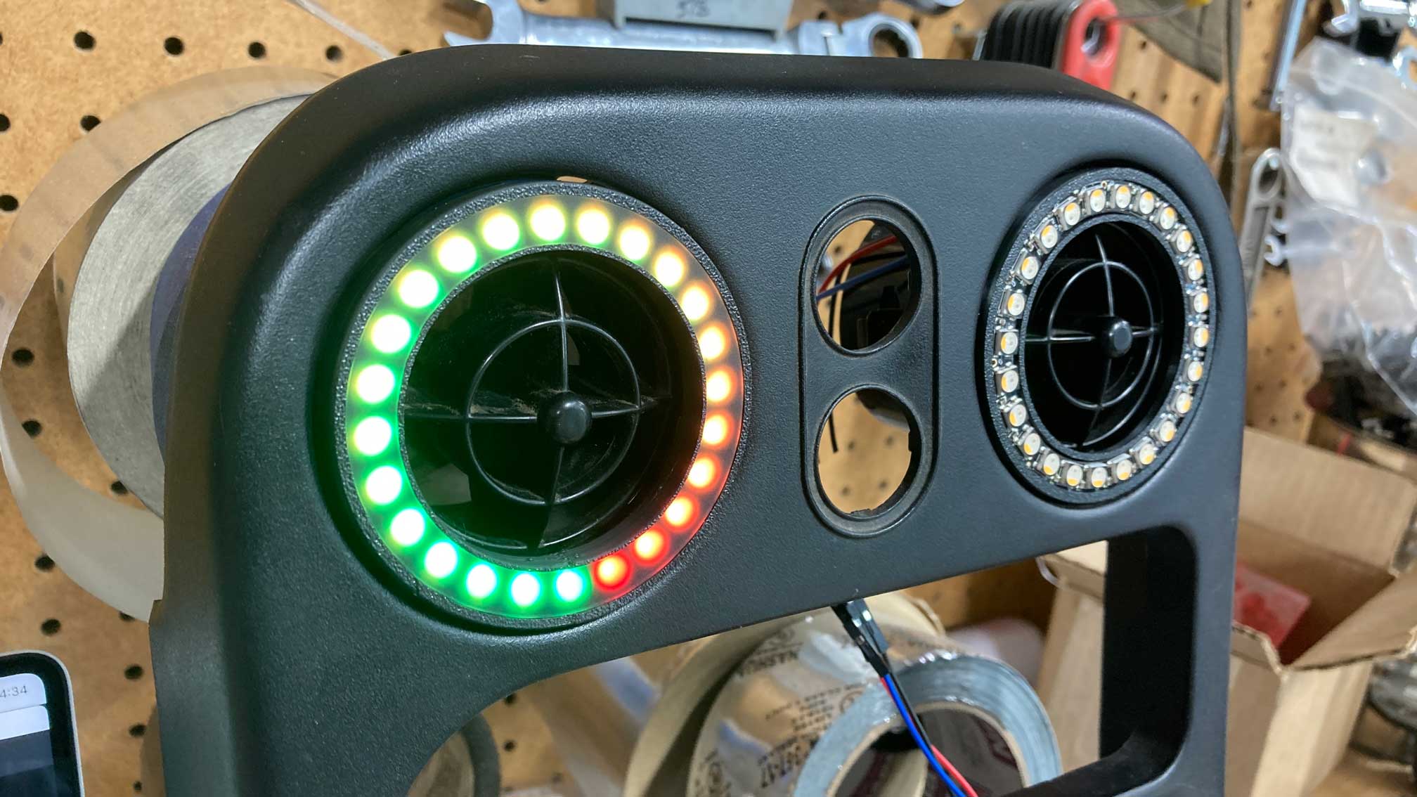
But I got distracted this week. I'd built a thing to put a clock in the "eyeball vent" on the Miata dash - people have been putting gauges in there forever because they fit really well. And one onlooker opined that it was silly to block a vent with a gauge and that he could look at his phone instead of a clock. Obviously, I do not agree. But the design process for the mount had me thinking about it, and digging through my LED stash I came across a ring of LEDs that happened to be a very convenient size.
So this happened. Version 1.
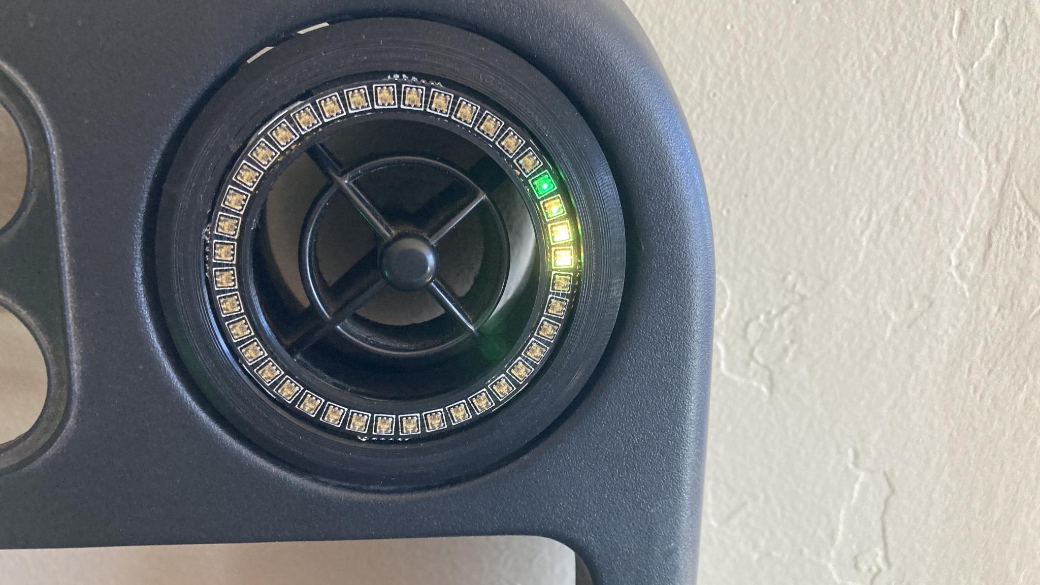
And then, a little prettier, version 2. It has better wire routing, does not require any modifications to anything to install and does not impede the movement of the eyeball in any way. This is running my "friction circle" code that ported over very easily.
Why did I put this in the race dash build thread? Well, the way I built out the components, I could use them to run one of these. I've already had a lot of questions about "what can you make it do?", mostly from people who want a shift light. I have some new components on the way that will make them easier to run off the race dash parts. Thanks to all the R&D and learning on the race dash, it was really easy to implement.
Now that's cool.
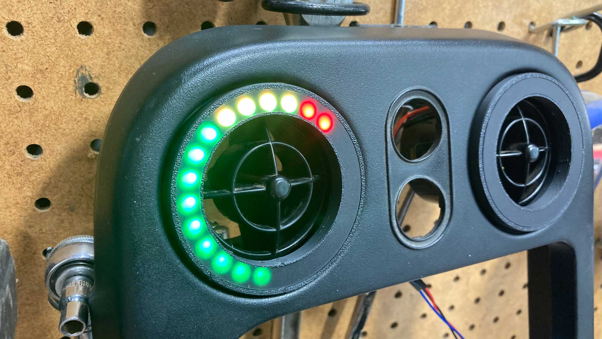
Next version with a different LED ring and (optionally) some diffusion plastic. This one uses the same sort of LEDs as the production race dash, so it can run off the same electronics. I'll have this in a car probably tomorrow.
Awkwardly silent video.
Heh heh.
This actually proving that my choice of architecture was good. The code is basically the same as the race dash. The microcontroller, i/o board and LED driver board are the production units for the race dash. Even the keyboard literally plugs in and is activated with about three lines of code.
You'll need to log in to post.


