1 2 3
bluej
bluej SuperDork
8/12/15 10:16 a.m.

Next time out, or even just driving around the hood of your shop, I'd love to see a video of what the rear suspension/subframe is doing. Something like a gopro mounted to the back of the main vertical rollbar right behind the drivers shoulder and angled down.

jpnovak
jpnovak Reader
8/13/15 9:01 p.m.

Just watch the video link and look in the Pass mirror. Good shot of top of tire, spring and overall suspension loading.

Looks like a fun little car. I might have to check it out next time I drive up to the Metroplex from Austin.

adoyle88
adoyle88 New Reader
8/15/15 3:38 p.m.

In reply to bluej:

We will try to get all kinds of camera angles next time. The plan was to get several different angles last time but with it being the first track day, we were pretty scatterbrained.

In reply to jpnovak:

Definitely contact us before your next trip up here. Maybe you could catch us on a track day. Also, we have tentatively scheduled to drive down south to show the car at the Houston Autorama. That is still a good drive for you but I just wanted to let you know.


We had planned on going to an autocross or track this weekend but decided we should work on the shop instead. Yesterday, in preparation for the track, we machined some pieces to help improve the rear suspension.

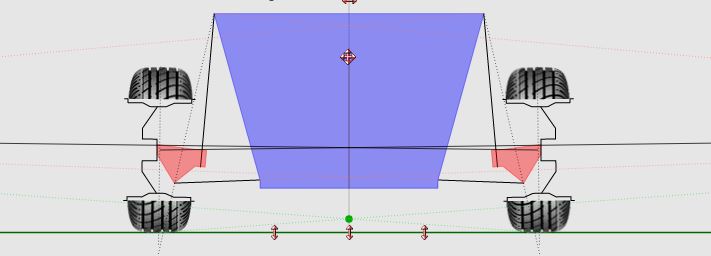
The main problem we had out at the track was that the rear wanted to rollover way too much. Drawing the rear suspension on a web app called VSusp, we found out that our roll center was far too low, creating a large roll couple. To make matters worse, as the rear rolled over, the roll center took off vertically and laterally, making the roll couple even worse. This explained the excessive roll.

To remedy the situation, we decided to lower the ball joints attached to the bottom of the suspension uprights. This would raise the roll center, make it migrate less during roll and angle the lower control arms in such a way to increase camber gain.

Before lowering the ball joint (roll center height: 2.5 inches): DF Goblin Prototype 2 old roll center

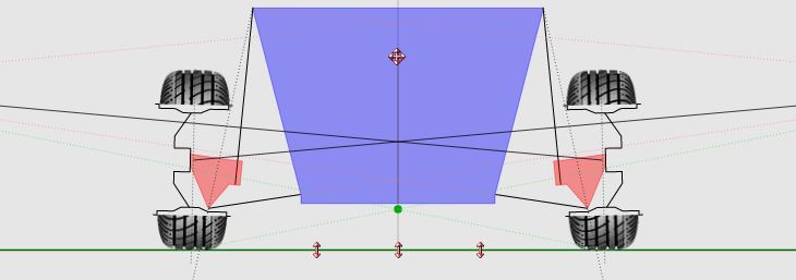
After lowering the ball joint (roll center height: 6.5 inches)(we also adjusted the height of the strut towers for stiffer springs): DF Goblin Prototype 2 new roll center

We were afraid of simply extending the ball joint mount down below the original because with the added leverage, we were concerned about the strength of the knuckle. Instead, we decided to make a piece that connects to the knuckle in 3 places to distribute the increased load. Here's what we ended up making:

DF Goblin Prototype 2 roll center adjuster plates

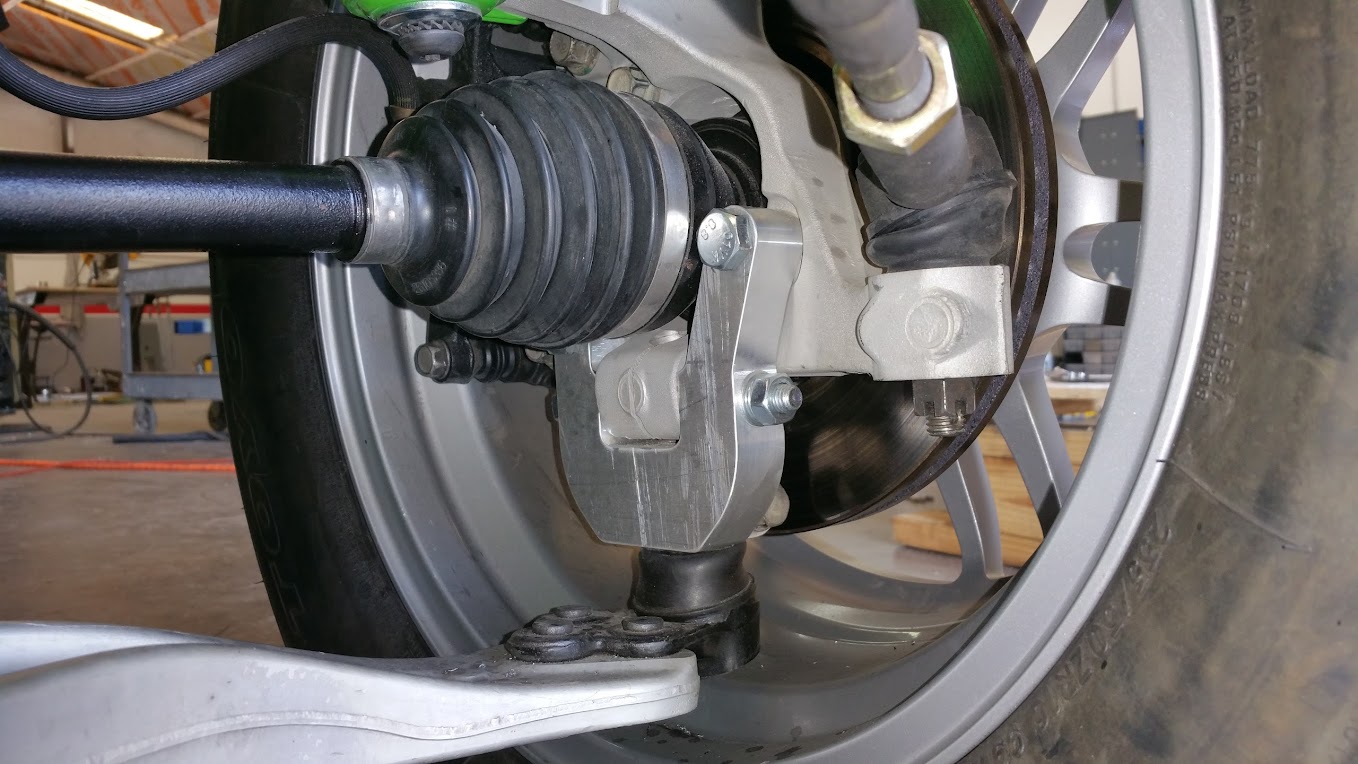
We later found out that many people use extended ball joints called roll center adjusters that appear to not break the knuckle, but we feel safer with the plates we made.

Before adding the roll center adjuster plates, we did a big left hand circle in our parking lot at a controlled speed to see how much it rolled over. The right strut compressed 3.375 inches just doing this. After adjusting the roll center, we did the same test and it only compressed 2 inches. Finally, we added stiffer rear springs and the strut compresses 1.5 going pretty hard in the parking lot.

We feel like the rear is way more under control now and the car should perform better the next time we get to the track.

burgerga
burgerga
8/20/15 5:57 p.m.

Looking awesome! Hope to see more track results soon

Stumc
Stumc New Reader
8/24/15 5:25 a.m.

Wow! Amazing progress in such a relatively short time, you guys don't piss around.

I'd really like to scratch build myself a mid engined space framed something or other kindof like this in the next couple of years, but this looks so much easier, it's almost simple to a fault if that can even be a thing haha!

Just curious, would you consider an option for a different rear suspension setup in the future? Double wishbone, pushrods/inboard dampers etc etc, Something with more adjustment for those people who might want to be able to play around a little and dial in the car to their preference. Allow people to have some input into the feel of the car, for better or for worse, if they wanted to.

What's the deal with getting this thing approved for racing, in hill climbs or time attack etc, just thinking specs for roll ages or whatever? Have you guys gone that far yet?

Flight Service
Flight Service MegaDork
8/24/15 5:50 a.m.

I have questions about your jig/flat surface

How flat is it?

Nice build all the way around

adoyle88
adoyle88 New Reader
8/26/15 5:03 p.m.

In reply to burgerga:

Thanks. We'd like to hit some more track days soon to test out some changes, but those days sure do eat up a lot of time. We've got to make sure each trip counts so we need to have all of our ducks in a row. I'll let you all know the next time we make it to a track.

In reply to Stumc:

We will definitely provide an optional upgraded suspension for the rear eventually. We aren't yet convinced the rear suspension we have now can't meet our needs with some tweaking but it is obvious that a double wishbone suspension would be far more adjustable for the track minded drivers.

I'm not sure about the car being approved for all of the various race groups but we built the cage out of 1.5 inch x .095 wall DOM following the guidelines in the SCCA and NASA books. I know some groups require fuel cells with bladders, so we would have to look into getting custom bladders made up for our fuel tank.

In reply to Flight Service:

We used a machinist's level to check the important surfaces of the chassis jig and we throw the level back on the tubes as we go. The front suspension is held to the jig with an aluminum framework that keeps all of the suspension mounting points in the right spot (this aluminum frame also locates the dash and dash accessories). The rear strut mount locations are set with a steel framework.


I don't really have an update about the prototypes at the moment. We've sold a few kits online since opening up for orders a week and a half ago. This has made us shift our focus to preparing the shop.

We've built a large chop saw table to make handling and chopping the tubes a lot more manageable. We also built a roll around cart to hold the material before chopping. We will eventually make some carts to move the tubes from station to station but at first we are probably going to do it all by hand.

We flat patterned all of the models for the brackets and mounts we use on the chassis. These were sent with some sheets of steel to the sheet metal shop to get cut out. We also ordered tubing. We are collecting enough tubes and parts to build up 10 frames.

1 2 3

You'll need to log in to post.

Our Preferred Partners
R7yoQQSjsGH26ibDNsDeQNRl2iMSAJKCXVCsyaZGFiRx7chexvgg7EYj9w8vKHxH