


When you put it that way, it seems so obvious! ![]()

When you put it that way, it seems so obvious! ![]()
This weekend started out with more unconventional jigging.
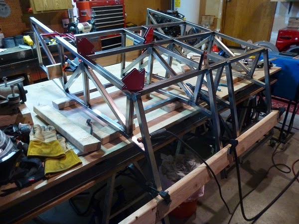
Once the tubes were all tacked in place, I had to try to figure out how to get the damn thing flipped and rotated to a more useful position. Needless to say, it doesn’t look like I’ll be able to maneuver the frame around for very much longer, without the assistance of my hoist. I would dare say that it’s almost starting to look like a real chassis.
One decision I’ve been mulling over, is how to build the upper portions of the foot wells in such a way that the transmission can be reasonably installed or removed.
![]()
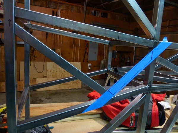
As you can see, the shifter stub protrudes up a bit and will probably require a considerable amount of jockeying to get it in and out even as shown with the transverse tube an inch higher than it would ideally be. One alternative is that once the final transmission tunnel tubes are in place, any tubes in the shifters path be removable. Eliminating them might work, but would be less elegant as it would require ‘creative’ bracing for the load paths to return to the tunnel behind the transmission. Getting the forward tunnel tubes cut and put in place should give me time to formalize a plan of action.

Looking good! Can you throw a measuring tape at that tranny and tell me what the bell housing to shifter length is? Also, over all length and width of the gear cluster section and the height of the shifter?
I'm going to flip a coin on keeping the T9 in my Spitfire build. Lot of people telling me the combo I have is probably worth more to someone building a "7" with the limited space. As much as I'm cutting on the Spitfire the MX5 trans may be just as easy for me.

Cut the tube below the transmission and make a bolt in brace.
In reply to jgrewe:
It's 18-3/8 From bellhousing face to center of the shift sub in neutral. From the front of the top cover to the beginning of the tail housing is 13. The width envelope is right about 9. The height at the shifter to the top of the shift plate is just under 13, and the shift stub protrudes just under 2 from there.
.
In reply to bgkast:
Interesting idea to make the underside removable, rather than the top side. Thanks opening another option!
As I sat in the chassis contemplating how to proceed, I couldn't help myself. I had to take the obligatory "vroom-vroom" pics:
Heading down to the local cruise night.

.
Chasing a Corvette through "The Kink" at Road America.

My brain is probably stuck on dropping the drive train out the bottom, since that's what I had to do on my build. ![]() in your case I envision you pulling the engine out the top by sliding it forward slightly, then using a load leveler to angle the engine up and the transmission down. That would make the lower bar in the way.
in your case I envision you pulling the engine out the top by sliding it forward slightly, then using a load leveler to angle the engine up and the transmission down. That would make the lower bar in the way.
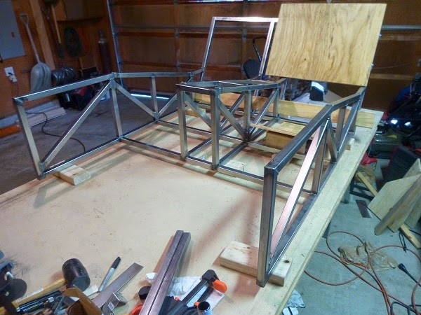
Two weeks have passed since the last update, and as many tubes have been fitted in that time.

Before I could decide on how much to angle the forward portion of the tunnel into the foot well space, I needed to track down and pick up a "backup light switch connector" from one of the local auto parts stores. That little plug is the point of greatest interference on the driver side of the transmission. After mocking it up different ways, and spending more time than a grown man has any right to sitting on a table pretending to drive an imaginary car to 'get a feel for it', a decision was made. It'll be tight, but by offsetting the transmission (and engine) slightly to the passenger side I should be able to get away with only a 2 inch taper on the driver side. That will still leave me with a generous 15 inches of foot well width for the driver...The passenger will have to make due with a bit less. That left me with just enough time to fit the lower tube that weekend.
This past weekend I spent some time sketching out a few options for diagonals across the floor pan. I settled on one that will allow the same diagonals to be used on both sides of the chassis, and should do a good job keeping my sensitive areas well separated from the pavement. I was only able to get around to fitting one of these tubes. But with a plan in place, the next series of tubes should be able to follow a bit more quickly.

In my last update I had cut and fit two tubes in two weeks. This past two weeks I cut and fit 8 more tubes. It's hard to complain about a 400% increase in productivity!
"Nothing endures but change" - Heraclitus.
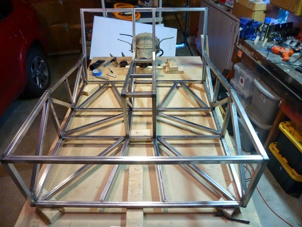
It’s been the better part of two months since my last update. This weekend was my first chance to get back to working on the car. All necessary holes for the floor diagonals were drilled, patterns were taken from the floor diagonals, and all of the floor diagonals are tacked in place now.
There is actually a very good reason for lack of progress though. Big changes have been happening around here, and I have embarked on a new ‘project’ in the weeks since my last update…
They say that good help is hard to find. I'm not sure who "they" are, but I need all the help I can get on this project. So in the Locost spirit, although anything but low-cost, we’re making our own helper.

It has already become apparent though, that she's the boss and I'm the helper.

Congrats!

Congratulations on the kiddo. She will take up more time than the build.
Love the build BTW.
Now, get back to it.
Thanks! She'll definitely be getting a lot more of my attention than the car. Luckily I have no expectation of being able to complete this build before she's old enough to be out in the garage 'helping' me anyways.
I like the "wait until the kiddos are sleeping, and sneek out to the garage" project technique. ![]()

bgkast wrote: I like the "wait until the kiddos are sleeping, and sneek out to the garage" project technique.
That's what I do - works out to about 1-3 hours per night depending on if I need just 3, or more like5 hours of sleep.

HHHHmmmmm.....Looks like a high RPM screamer to me. Bet it goes through a lot of fuel and has no pollution controls. I hear they can get temperamental with age.![]()
Congratulations on being selected as parents by what looks like a very charming young lady.
With the recent life affirming changes affecting my priorities, I think it’s going to take some time before I’m really able to get back into a consistent pattern of both progress and updates again. It’s also that busy time of year for other activities and obligations filling our weekend schedules. Another month has passed since my last update, but I am pleased to say that there has been at least some continued progress.
Three weeks ago I managed to get a handful of tubes cut. The long pair with the angled ends are the forward top tunnel tubes, the mid length pair with the squared ends are the vertical tubes on either side of the transmission at the firewall, and the short pair with squared are part of the top and bottom transmission tunnel reinforcement. My next update should be of these tacked in place.

Two weeks ago was a mini-meet of local homebuilt car (Locost) enthusiasts. There were two with completed cars that showed up, and two (including myself) that are still slaving away in our garages. I’ve seen the proof with my own eyes, that these cars CAN be completed!

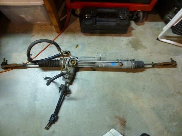
And one week ago I picked up potential steering rack, as this will be a critical component in designing the front suspension. The most readily available aftermarket production-based racks are probably the Ford Mustang units, which works well with my Ford component theme as well. It would seem that similar critical dimensions can be had with the right outer tie rod end selection on Mustang II, Fox Body, and SN95 chassis Mustang steering racks. I’ve been looking at dedicated manual racks, as the depowered Mustang racks seem to get significantly more negative reviews than positive. The Mustang II manual racks are simply too slow at 1.3 to 1.4 inches of rack movement per turn of the steering wheel. The aftermarket manufacturers have “quick ratio” manual racks for the Fox Body, but they’re still a bit on the slow side at 1.6 to 1.75 inches per turn and keep nudging the budget up. The SN95 never came with a manual rack from the factory, but also has a similar “quick ratio” aftermarket manual rack that seems to do little more than use different thread pitch tie rod ends and add cost over the Fox Body Racks.
However, I do also know that depowered racks are popular with Miata drivers and typically get positive feedback. So I when I came across an OEM power rack for a Fox Body Mustang at the right (low-cost) price, I jumped at the chance to buy it. Before making any final decisions on the front suspension design, I will be attempting to disassemble this rack to get a good look at the internals and determine what modifications might be possible to use it successfully in the depowered state. A preliminary check show that the Fox Body power rack appears to have ~2.2 inches per turn.
Somehow the acronym SWMBO (She Who Must Be Obeyed) never really seemed appropriate for my wife, so I gave her the much more deserving title of SWEETA (She Who Enables Every Thing Automotive). Maybe it was a coincidence, and maybe it was a premonition. There is no way to know for sure. What I do know is that with a baby girl in the house there is one, and only one, SWMBO...And it certainly isn't my poor SWEETA.
As weeks turned into months of virtually no progress, in the back of my mind I did start to wonder when I would ever be able to get back into the swing of things with this build. Fortunately, SWMBO has appears to have recently approved my request to exchange the previous weekend mornings for weekend nights, by regularly falling asleep considerably earlier. Additionally SWEETA has given this new schedule her blessing as well, by also choosing to go to bed at that time. Thus, for the past 4 weekends in a row I have gotten garage time!
Unfortunately, I have spent more time that I care to admit relearning some of the things that I was doing without giving a second thought before SWMBO arrived. Consequently, I have also spent far to much of this precious time redoing said things...Often more than once. As of this weekend, it feels like it's all starting to flow again though.
Current progress is limited to having tacked in the tubes from my last update, and having cut the 4 additional tunnel diagonals sitting in the chassis as pictured below. Yes the chassis as pictured is currently up on its side, so that's three bottom diagonals and one upper diagonal.

Welcome back! I so very well remember the balancing act of a new family with my need for shop time. The shop time took a back seat for a few years; still a haven, but not a priority. Somehow, mine went from newborn to 20 year old in University in the blink of eye.
I'm not sure what it is about painting supplies, but they're just so damn useful for stuff other than painting. I had previously written about using the stirring sticks for setting the angle on my band saw. Now I'm using painters tape to lay out and cut my tubes to the right...err...correct angles and lengths.
The basis of this technique is something that I picked up from forum member nocones for making compound angle cuts. However, I decided to use it to see if it might also be able to simplify cutting some types of 2D tubes as well. A diagonal tube between parallel planes in a rectangular opening is relatively easy to math it out. But it adds another layer of complexity when the opening is not rectangular, nor symmetric for that matter, and the tube is not between parallel planes. Thus I figured this would a perfect time to practice an alternative technique.
First I spent some time figuring out exactly where I want the tubes to go. These tubes also happen to be going beneath the transmission. So I had to make sure to avoid the lowest parts of the transmission, try to leave at least some emergency access to the drain and fill plugs, and adhere to my personal guidelines of avoiding overlapping weld joints and angles tighter than 45 degrees. The latter of which I forgot about last weekend until after the tubes were cut, sending me back to the drawing board...Literally. No fancy CAD programs here. Just good old fashioned graph paper, a pencil, and a ruler.

The process then starts laying painters tape across the span where the tube will go. Measure out the desired corner points based on the design, marking them with a Sharpie. After that, use a large enough straight edged device and play connect the dots.

Since the Sharpie can be seen through the tape, I find it easiest to lay the tape sticky side up on the table and align the tube on top of it. Then flip it over to clearly see where the cuts will go.

Now my band saw only angles in one direction. To cut angles the other direction, you simply flip the part over. With both cuts going opposite directions, only one of them can be cut with the tape side up. Align the cut line on the tape with the cutting blade, lock it in place, and let it rip.

With the tape having been cut as well, it now becomes the transfer pattern. To make it stick to the other side of the tube, place a couple strips of tape sticky side up on the table, lay the transfer pattern tape sticky side down on top of them, and align the tube on top of that matching up the previously cut ends. Now wrap the sticky side up tape strips around the tube to hold the transfer pattern in place. Roll the tube over to see where the cut needs to go, and using a center punch or scribe, mark the desired cut line in the tube.

At this point the tape can be removed, revealing the line to cut.

And voila, a finished tube!

Lather, rinse, repeat.

I knew from the start that this method might provide slightly less accurate cut positions and angles than I get from my hand calculations, but it proved to be quite a bit more accurate than I had anticipated. I was impressed with how easy this technique was to get a feel for, as well as how little 'massaging' will be require to finalize the tube fitment. Just remember that it's a LOT harder to cut material back onto the tube, than it is to cut more material off.
I picked up some garage essentials this weekend...Maybe this will finally solve the Sharpie-Cockroach Paradox.

Transmission tunnel triangulation tacked.
![]()

Dude! This is awesome!
How much is this chassis going to weigh?
Keep going!
I'm really not sure what the final weight will be, but with my chosen design path it will certainly not be the lightest Locost chassis. This should be the heaviest portion of the chassis, and as it sits it's up to ~90 pounds. The plan right now is that this area will be steel paneled as well. So I wouldn't be surprise if the completed chassis is in the 250-300 pound range, when all is said and done...Depending on how exactly one defines "complete".
I know you are using an alternative joint design to avoid overlapping welds, but have you considered how you will get the welding torch into some of those tight junctions? Getting good welds in tight spaces has been the hardest part of my build.
You'll need to log in to post.


