


My God![]()

My God![]()

Here is the start of my front custom suspension. There are no really good options for Insight suspension upgrades so I made my own.
Like I said in the beginning I plan to use Fortune Auto 510 coilovers. These coilovers started life as 02-05 Civic front coilovers. I am using spindles from a civic as well because it allows me to use a larger axle and brakes. From there I had Fortune install their new high range adjustment valves and 4K springs.
I used kinematic software to calculate a spring rate that would give me a decently comfortable ride as well as having the ability to stiffen up when I wanted to go roundy round. Fortunes new high range adjustment valves allow you to artificially add spring rate. This is great as it will allow me to have that smooth ride and weekend fun car with one setup.
Here are the Fortune Auto 510 coilovers.
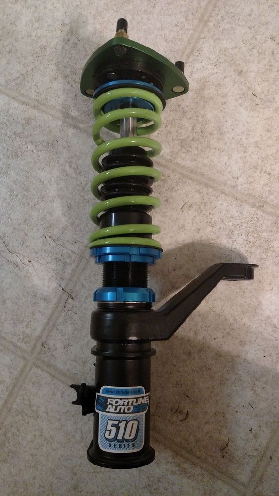
Clearly the first problem would be is that the tophat on the Fortunes are not the same as the tophat needed for the Insight. I looked around for tophat/camber plates but could not find anything for the Insight, so I decided to make my own.
This is what I came up with. This is the second version as I designed a first one and I didn't quite like the range of adjustment. You can see the difference in the comparison below.
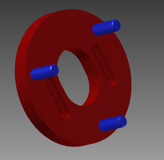
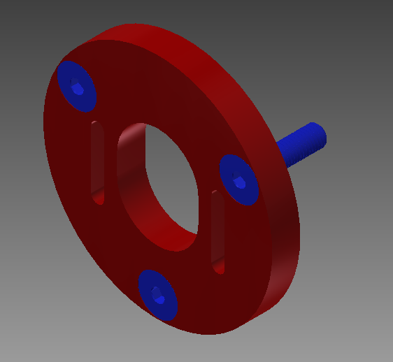
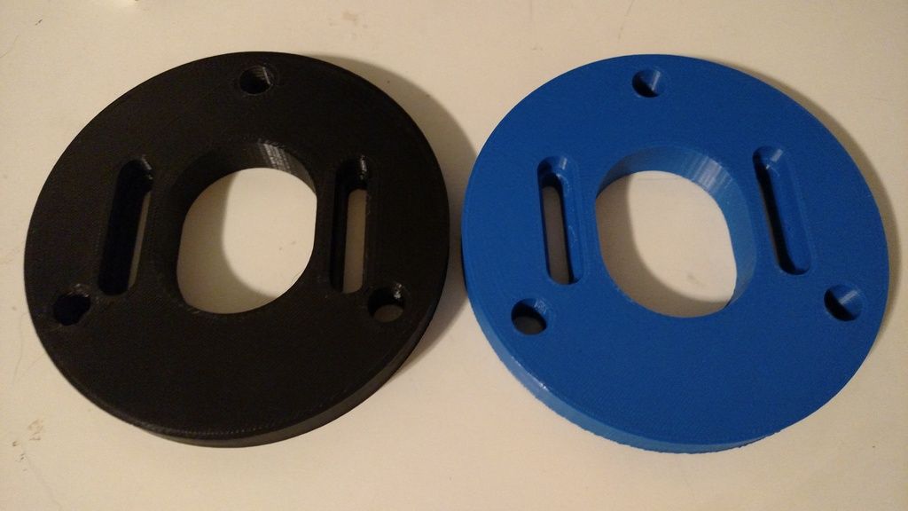
Here are the first and second design 3d printed. Black is the first and blue is the second. The adjustment slots are shifted upwards slightly and this gives a slightly higher negative camber adjustment.

This is turning out really nice. Could you email me inskeepwp@gmail.com for information on the removed insight parts. I'm in VA and can make the trip out that way.
Thanks -Paul
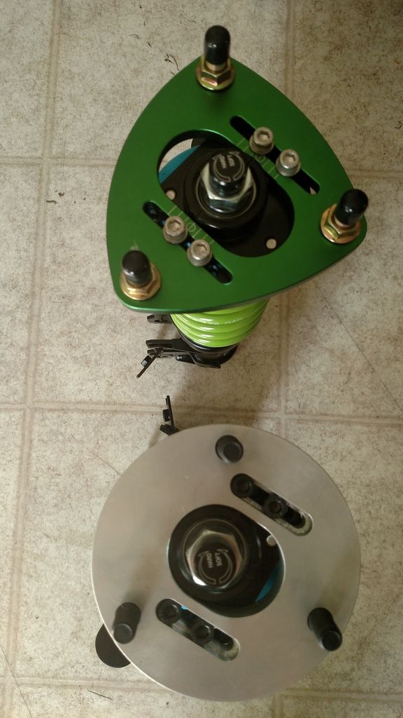
Once I was happy with the design, I had the tophats machined out of aluminum.
Here is the new tophat compared to the one for the Civic.
The next issue to tackle was the lower control arm ball joint. I have seen other setups where people weld the Insight spindle insert into the Civic Spindle. I planned to go this route but with a custom made insert.
Here is the insert I came up with. Pretty simple and easy to press into the Civic spindle and weld.
After I did this I realized that with everything installed the lower ball joint pin hits the axle. I could cut down the pin for clearance to the axle but then I would lose the cotter pin. On top of that, I thought about serviceability and I would have to remove the axle every time I had to do something with the the lower control arm, Which means I would have to remove the strut. This is why I decided to start over.
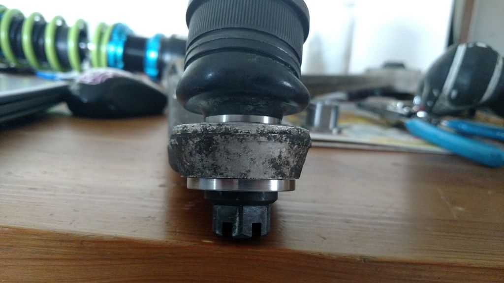
The other option would be to modify the lower control arm to accept the standard Civic ball joint. I started by removing the ball joint from the arm and facing both side flat and parallel.
Here is the arm after machining. I nicked the arm a little when I was removing the ball joint. This is just a test arm anyway.
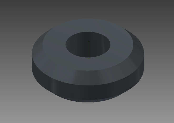
With the arm ready to accept an insert, I designed one with correct taper and came up with this.
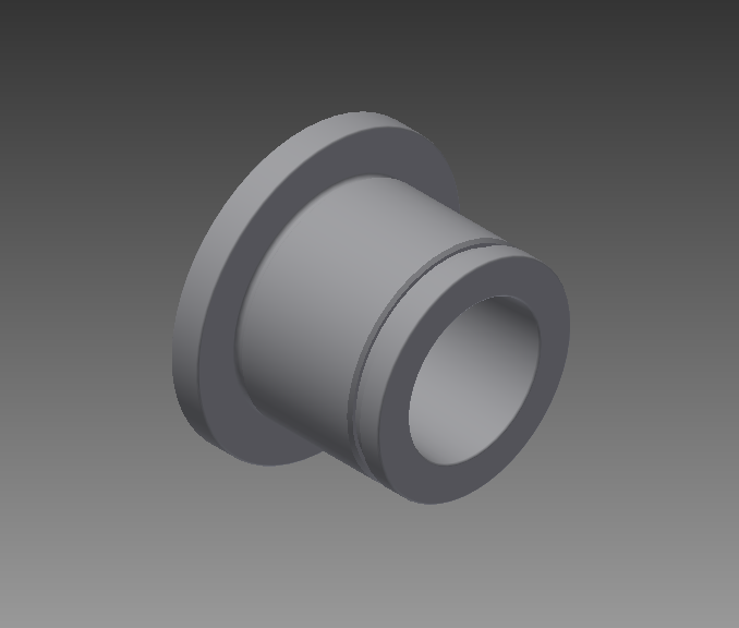
The insert will be pressed into the arm, have loctite around the OD and have a snap ring to make sure it doesn't move. Safety First
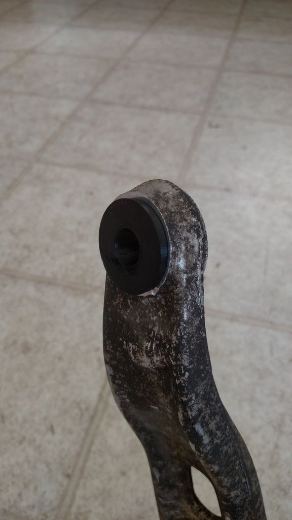
Here is the insert 3d printed and pressed into the arm. This one does not have the snap right groove but you get the idea.
I like your approaches of 3D part then final. This car must be pretty far along as this is proper R&D methods.
Keep em coming.

This is awesome. I have seen people use the Civic suspension bits but not really 'how' they did it. Thanks for the detail! Also, I think that there is a market for these parts with the insight world. There are a lot of people looking for suspension solutions and having to send their strut housings to Gaz in the UK. This is likely a better option and would end up in the same ball park price wise. If you have any interest in selling parts and want to chat about how to approach it, please hit me up. I have dabbled in this field before.
catapultkid wrote: I like your approaches of 3D part then final. This car must be pretty far along as this is proper R&D methods. Keep em coming.
3d printing the parts first has helped a ton. I find problems I may not have been thinking about and I am out very little money when I do. It also helps me improve the parts if I think of something else along the way. The 3d printed top hats were strong enough that I bolted them to the car with the strut and made sure everything fit correcly. Very Very Helpful.
singleslammer wrote: This is awesome. I have seen people use the Civic suspension bits but not really 'how' they did it. Thanks for the detail! Also, I think that there is a market for these parts with the insight world. There are a lot of people looking for suspension solutions and having to send their strut housings to Gaz in the UK. This is likely a better option and would end up in the same ball park price wise. If you have any interest in selling parts and want to chat about how to approach it, please hit me up. I have dabbled in this field before.
I went a little over the top with my designs as I plan to drive the wheels off this car and always build with racing and safety in mind. I have been talking with Fortune Auto about making a lower mount that would bolt directly to the Insight spindle, then I would provide the Top Hats to make the set complete. That is still in process so we will just have to wait and see. More people are swapping these cars now and I am sure a more comprehensive solution would be helpful. I will get a hold of you and we can talk about it.
I know I'd be interested if that materializes. I've been toying with a building a SMF insight for sometime and I'd love to be prevoked a bit more and test some parts. Plus Fortune Auto is local to me.
The real development needs to happen in the rear.
In reply to proawemike:
I really wanted to swap mine over but life happens and it is difficult (and maybe illegal) to put an infant in an Insight. However, I am hoping one with a couple 100ks and a dead battery shows up and I can snap it up for little to nothing for this very purpose.

The 3D printing is amazing. This technology really changes everything in term of hotrodding (assuming one knows how to do it).
The fabbed parts look fantastic, too!
I really want to get a 3d printer but the one I want is $600 too expensive, IE it costs $600.
singleslammer wrote: I really want to get a 3d printer but the one I want is $600 too expensive, IE it costs $600.
If you or anyone really, is looking for 3d printed parts I have two and make prototype parts for some side cash.
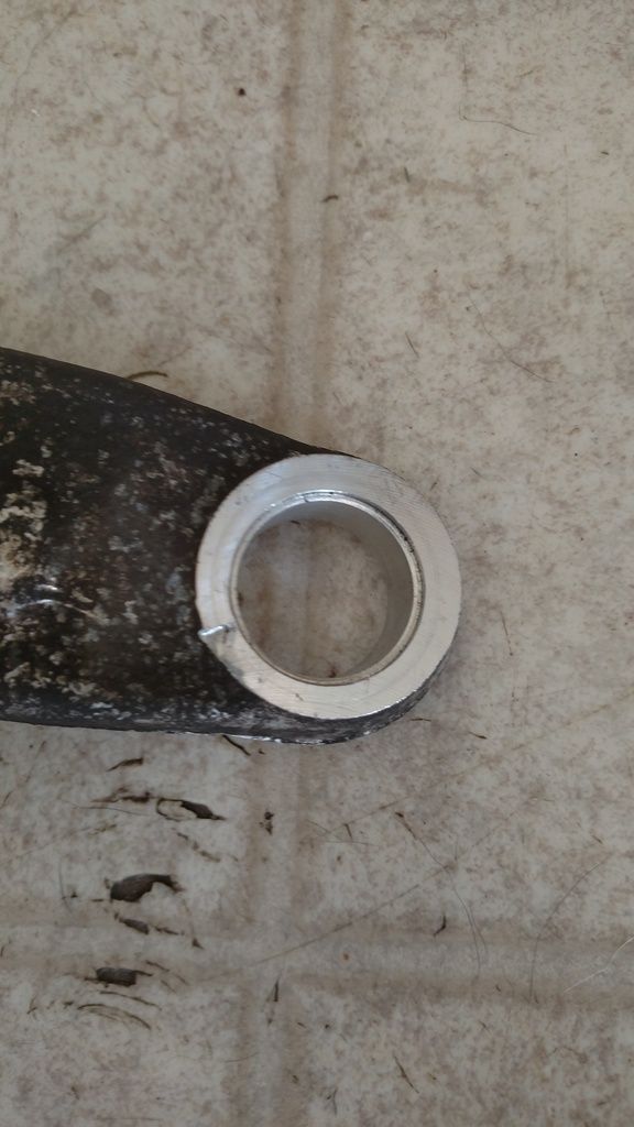
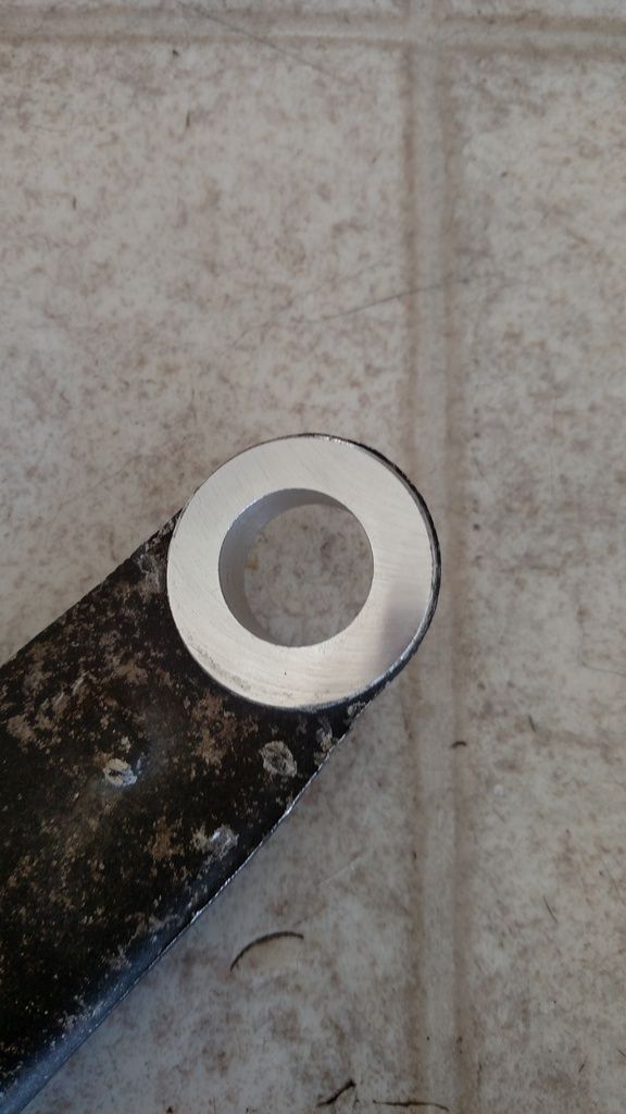
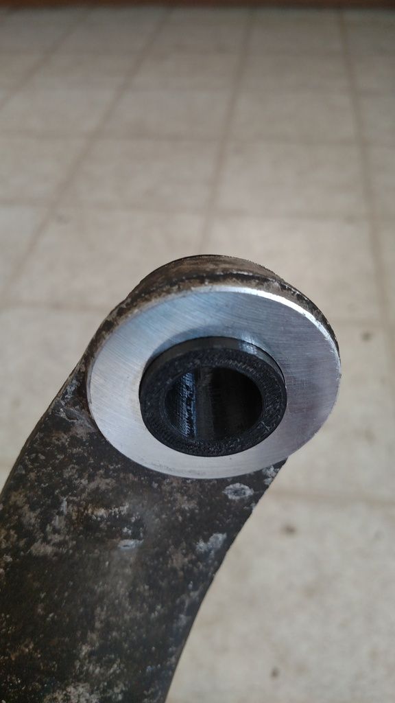
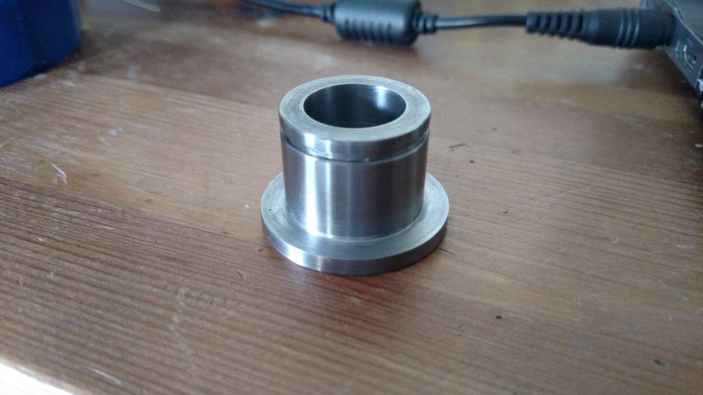
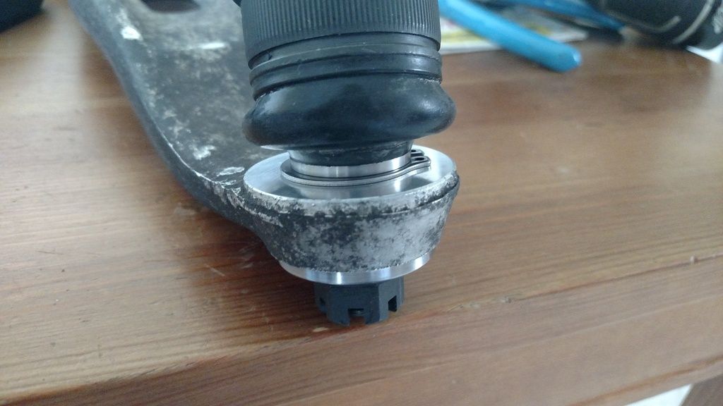
Here are some pictures of the finished lower control arm insert. It fits really well and will make sure the suspension works like its suppose to.
That is awesome amounts of home brew overkill (I say this as a completely good thing). I will keep your prototyping in mind. My issues will start higher up the 3d printing food chain since I need a file to send you.
singleslammer wrote: That is awesome amounts of home brew overkill (I say this as a completely good thing). I will keep your prototyping in mind. My issues will start higher up the 3d printing food chain since I need a file to send you.
Haha I will also do CAD work.....

That is some incredible fabrication work. I didn't really expect to come back to this thread and find that the Honda full of PO bullets riding on cut springs had become a DTM racecar in just over a week.
So today's update is going to be the install of some S2000 seats. This is going to be relatively straight forward and just house a bunch of pictures. Here is a low miles AP1 S2000 seat.

To start I Took some 1/4 steel bar and cut 2 tabs out of it for the back mounts.

Then cut some slightly longer 3/16 plates for the front and bent them to match the shape of the stock cross bar.

I measured the sliders on the S2000 seats and outside to outside they are 18.75", So I cut some 1/4 bar and some 1" tube to that measurement. I bolted my tabs down and came up with this. The 1/4" is for the front of the seat mount and the 1" square tube is for the rear to get the seat off the floor.

The rear mount toward the out side of the car was in a little divot, about 1/4", so I raised it up with a piece of 1/4" bar stock.

Next I laid the 1" tube and the 1/4" bar across the mounts and pushed them towards the center of the car as much as possible. The S2000 seats sit a little outboard naturally, so pushing them inboard is the only way to get them centered up. The S2000 rails are 15" long, front to back. The distance between the front and rear cross bars must less, around 13", in order for the sliders to sit on the cross bars comfortably.

With The cross bars tacked into place, I moved on to removing the stock mounts on the seats. Start by drilling out these rivets on all 4 mounts.

Drilled out.

For the front there is an extra little spot weld right behind the rivet that needs to be drilled out as well. For the rear you need to cut the 2 welds that run forward to back on the rails. Once those are gone just wack the tabs with a hammer and presto. Tabs gone.
Sand all rivets back and the part of the weld that is left over and prep it to be tacked to the seat mount.
I put the seat in the car and did a test fit. Found my first issue. The bottom of the S2000 seat dips below the sliders. When the seat is moved all the way back it hits my 1" tube. The only reasonable thing to do here is cut the tube, so that's what I did.

But now there is a big hole in my seat mount. Have to fill that up.

All better.Now to put the rails back in the car.


Wow...way well done build.![]()
Next part is a little hard to show but I installed the seat into the car and put them on the rails. Centered it as well as I could and tacked it to the mounts. Pulled it all out and this is what I came up with.

Here you can see the clearance that I made in the rear tube for the seat. It looks bent in this picture but I promise its not. Haha

Test fit them back in the car and all was good. Final welded it all together.


Final part of the seat install is the seat belt lower mounts. I decided to use a captive nut for this in the end of the 1" tube. Basically the whole tube and mount has to fail before this seat belt is going anywhere.
I made a 1"X1" 1/4 plate steel insert and drilled a hole for the bolt.

Welded a extra thick nut to the plate.


Then the insert would need to be welded into the end of the seat rail assembly. I tapered the edges of the insert so that I would have good penetration on the welds.

I put the insert into place and held it against the outside of the tube with a magnet.


Welded it all up and ground it smooth. Pretty

I painted the entire mount and it was ready to go back into the car.

I will post a picture of the seats and the whole interior once I get it all completed. Sorry to spoil the pay off.
You'll need to log in to post.


