1 2 3
klodkrawler05
klodkrawler05 Reader
5/24/17 2:53 p.m.

Instead of posting little bits and pieces all over various threads here I thought perhaps I should make a condensed build thread of my car in case the hive was interested (and the weather is finally such that it's bearable to be outside messing with cars)

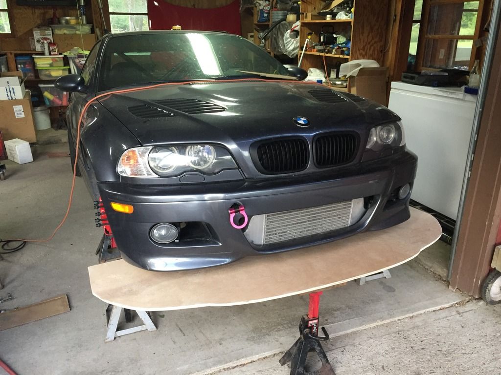
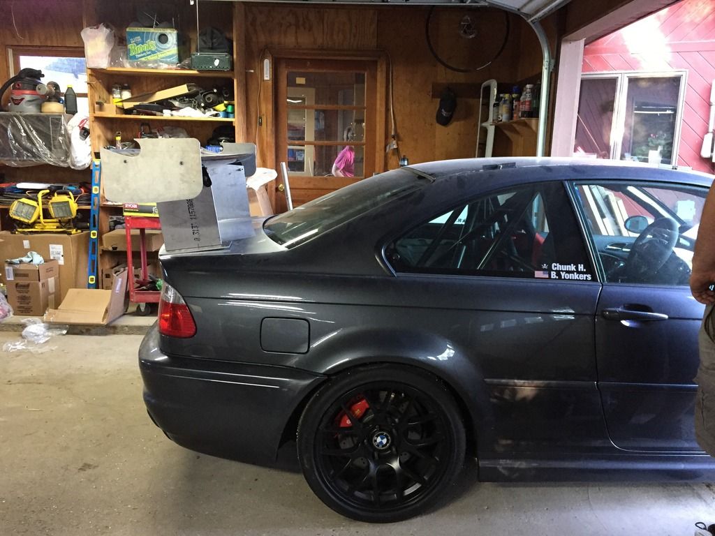
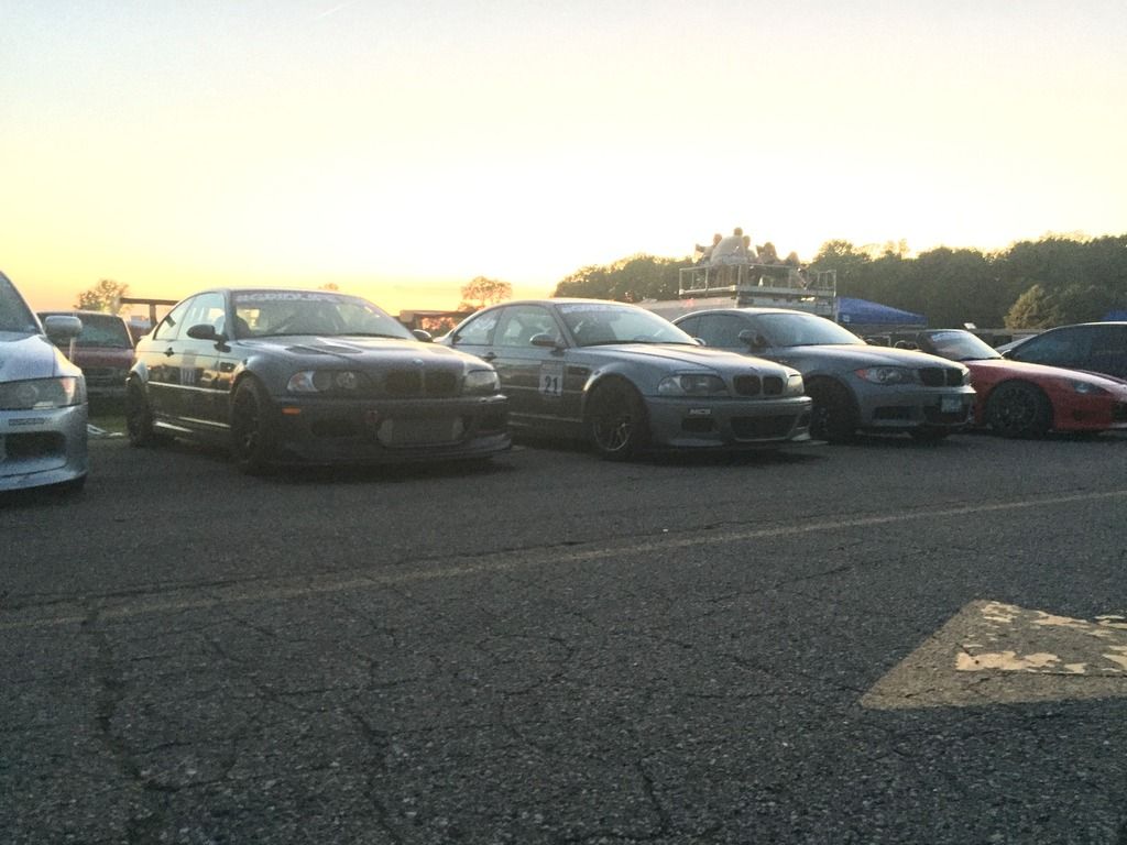
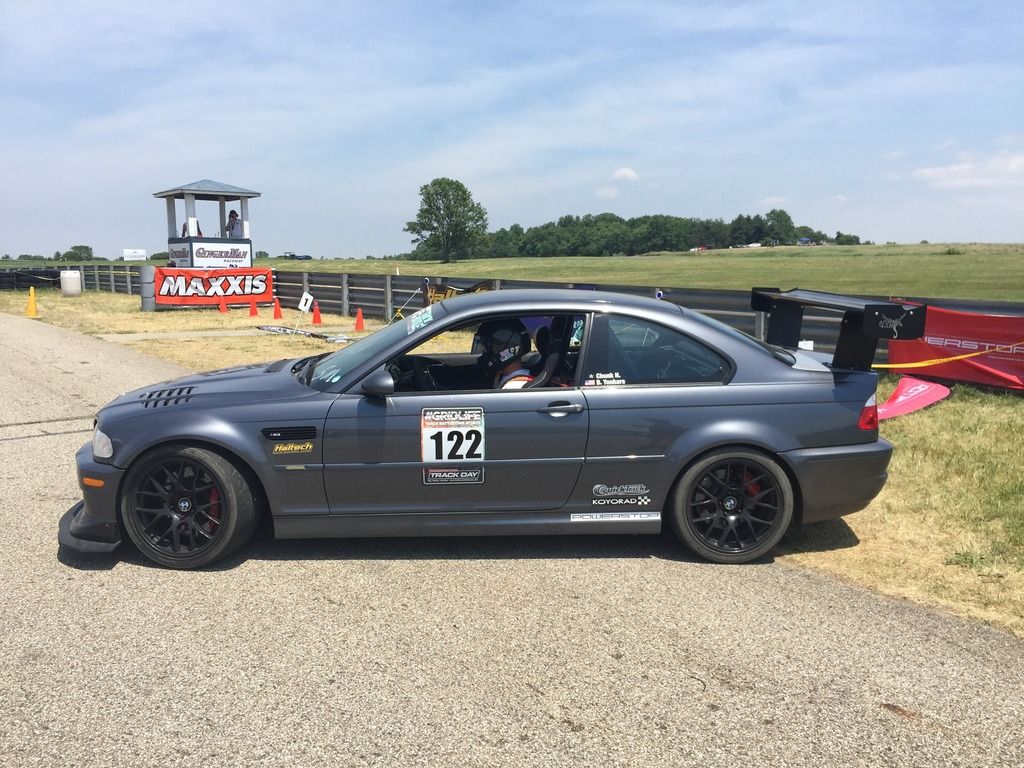
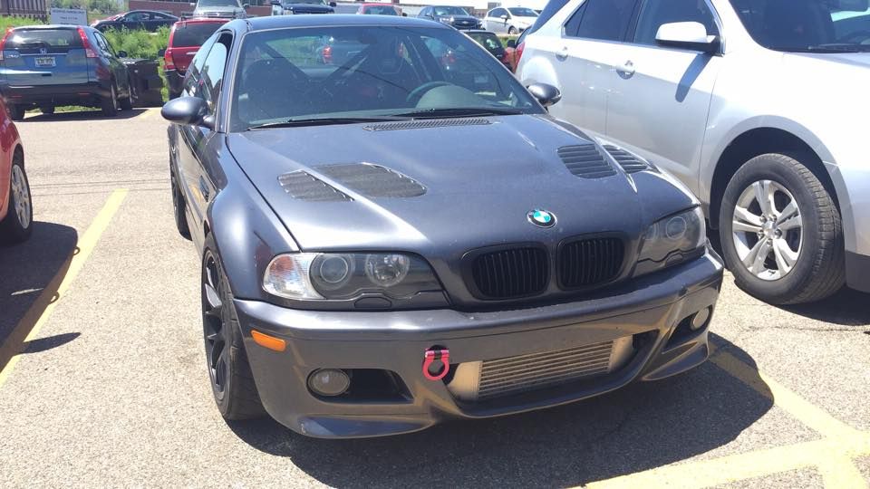
I bought this car like this:

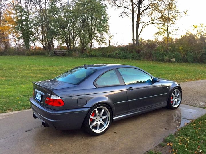
It was kind of higher miles but seemed well cared for and had every single part Dinan has ever offered for the car, which was perfect for me. Turning a stock car into a racecar means I wind up with a pile of parts nobody wants to buy that I feel bad about throwing away. Starting with a Pile of dinan parts means i've got a pile of parts I can turn into cash for racecar parts.

On that note the car did come with lots of spares, we drove my TDI jetta 10 hours away to pick up the car and then had to figure out fitting all this into the m3 and the tdi.

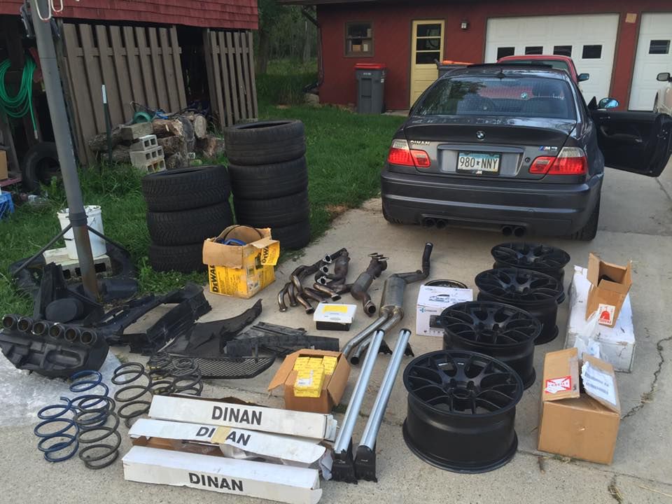
All the stock parts for the car as well as 4 snow tires and 4 used Michelin super sports. Between MI and MN I found a set of 18x10 apex ec7 wheels for sale on craigslist, I arranged for picking those up on our return trip as well because the 19" dinans on the car were heavy, expensive, and staggered

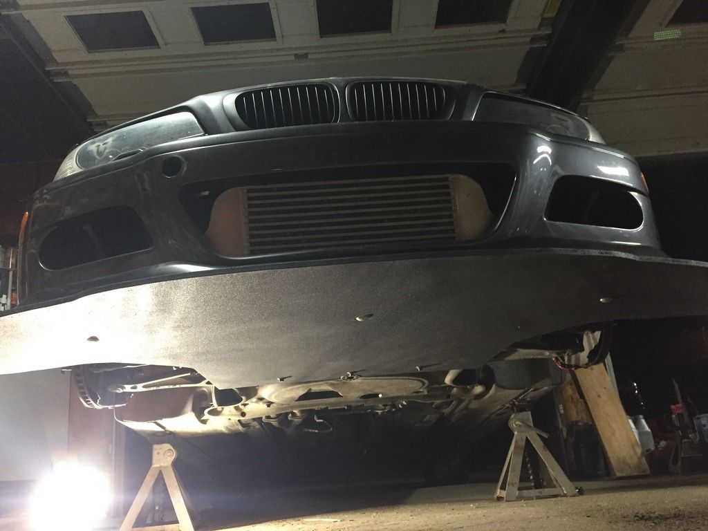
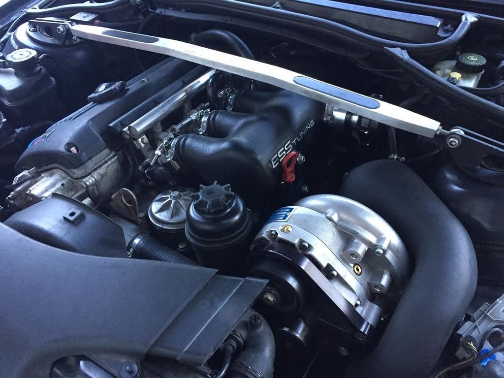
The Dinan savvy will be waiting for pictures of the supercharger, this car doesn't have that. instead it has an ESSTuning V550 kit. A fair trade off IMO, This kit has a massive intercooler and ESS tests the kits by doing hot laps at the Nurburgring so it should be fairly reliable.

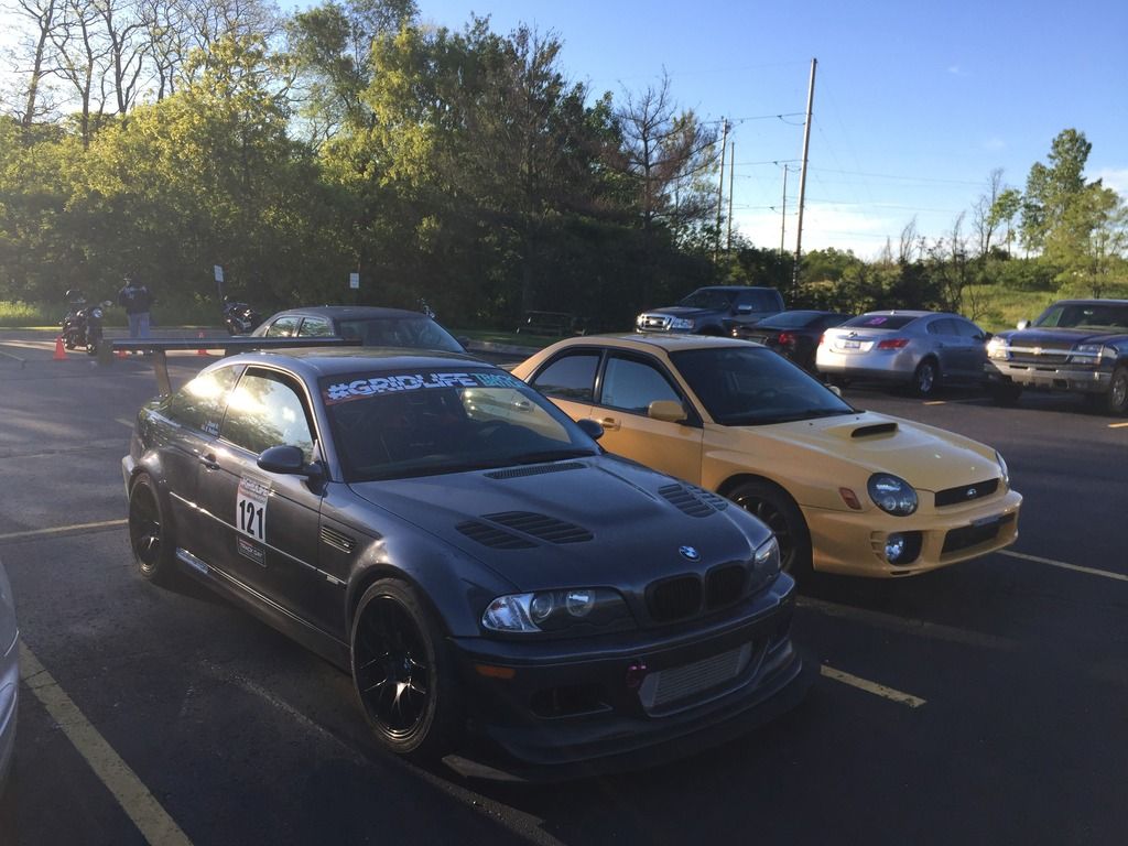
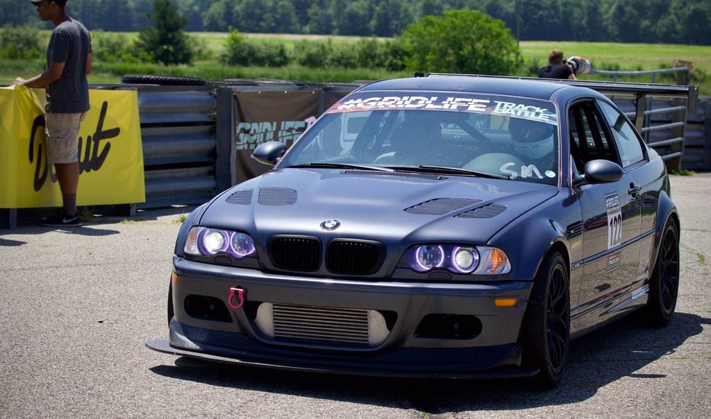
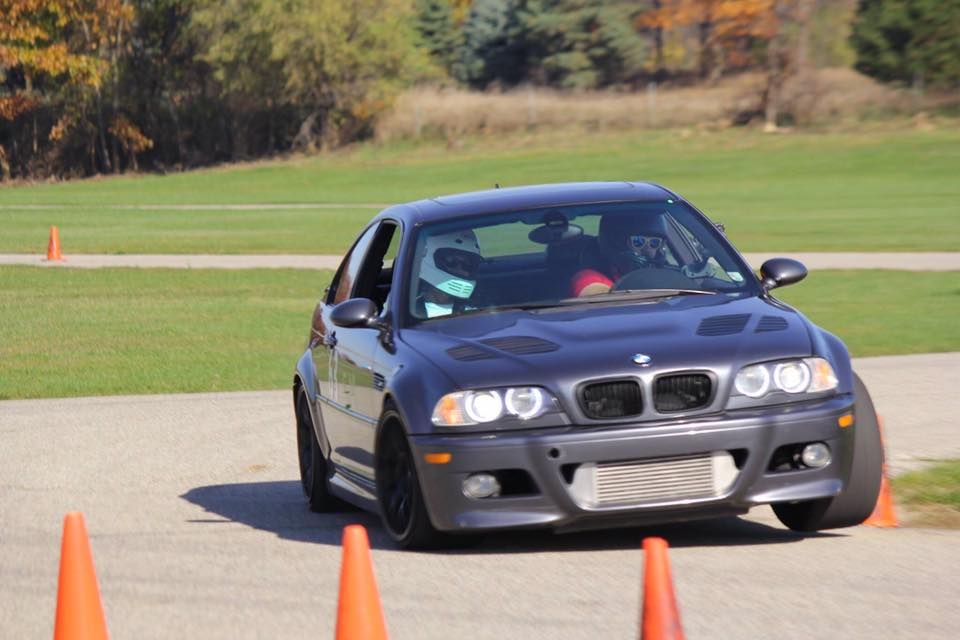
It seems I don't yet actually have a picture of the engine bay so, here is a photo from autocrossing it last fall, the 18x10's work great with 255 hoosier A7's and are plenty quick enough to contend for FTD at our local auto-x events:

I only got 1 auto-x and 2 lapping days on the car before winter hit, but that was enough to at least start a list of changes.

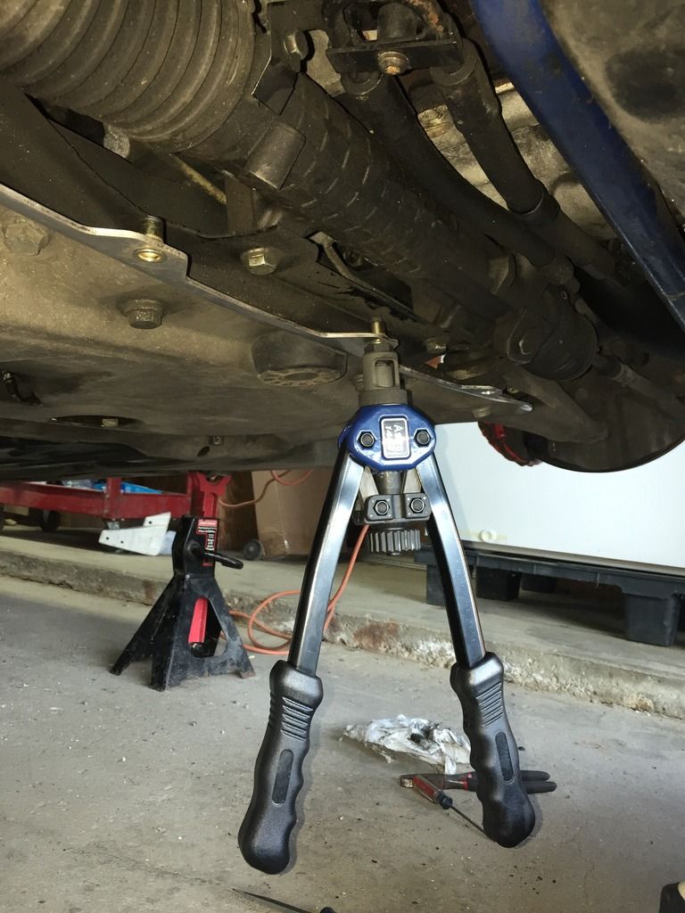
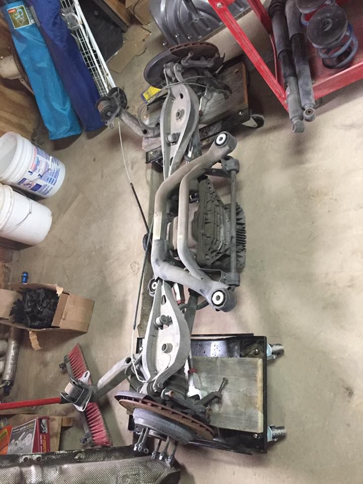
Step 1, replace the rubber rear bushings with bimmerworld sphericals, additionally while the Dinan 3.92 lsd was probably pretty nice for a stock power m3 the shorter gearing just meant you arrive at redline that much earlier for Auto-x and track days, traded for a stock diff 3.62 differential plus enough cash to cover the spherical upgrades!

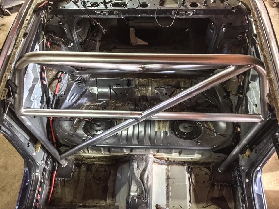
Next, the car was already fairly heavy as far as e46 m3's go, it had about every option, plus I added a roll bar which was even more weight. Note: factory seat replaced with OMP saved a few lbs:

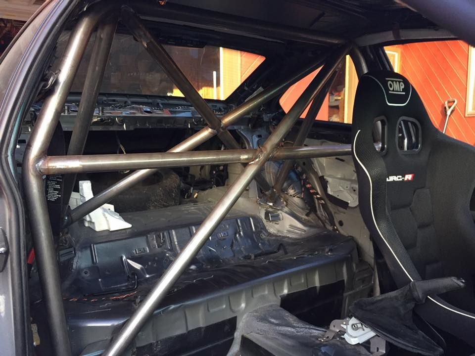
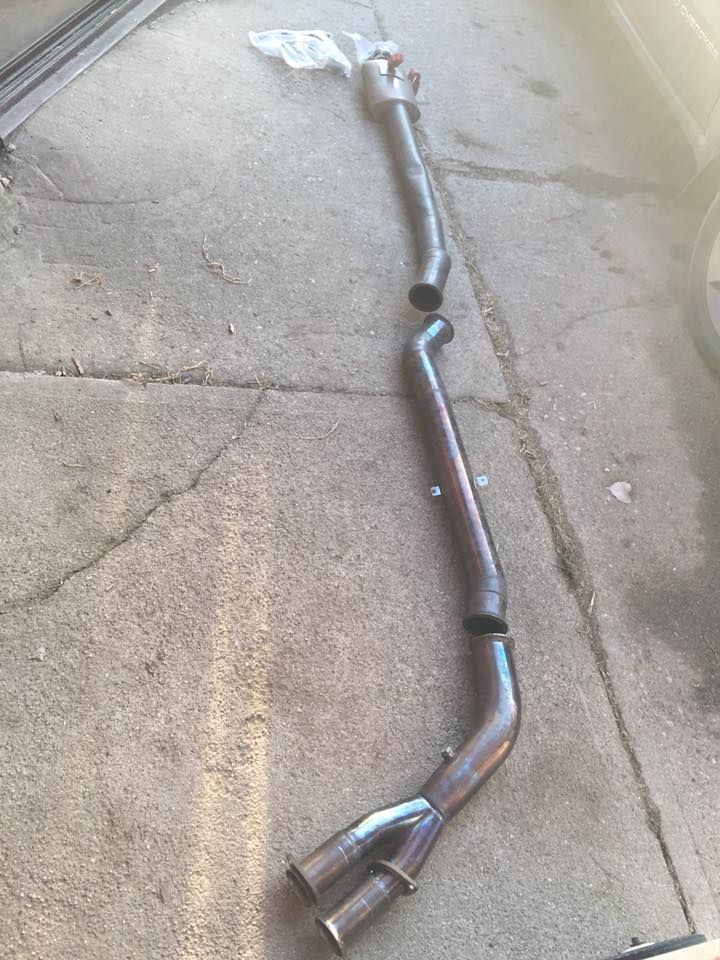
So I canceled the roll bar weight gain by replacing the dinan exhaust with a bimmerworld race exhaust! this cost nothing as the dinan systems are fairly sought after and I found the bimmerworld used for cheap and didn't have to ship:

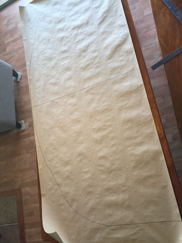
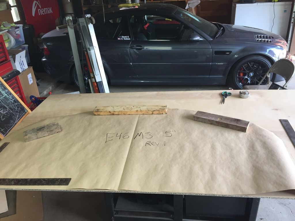
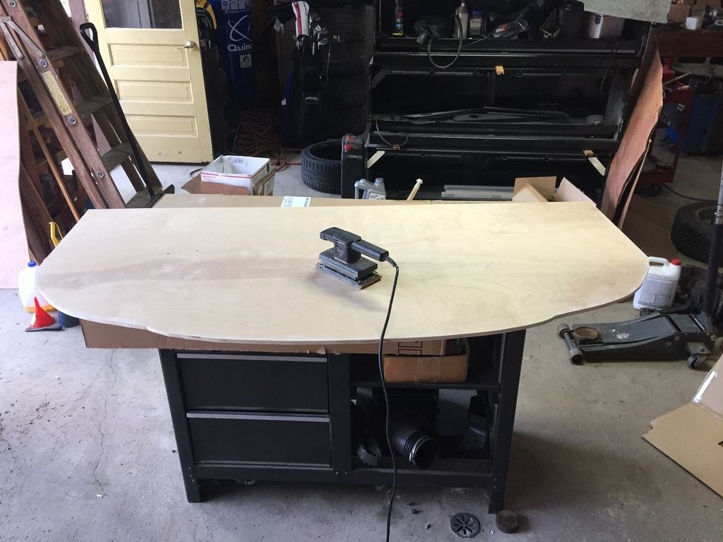
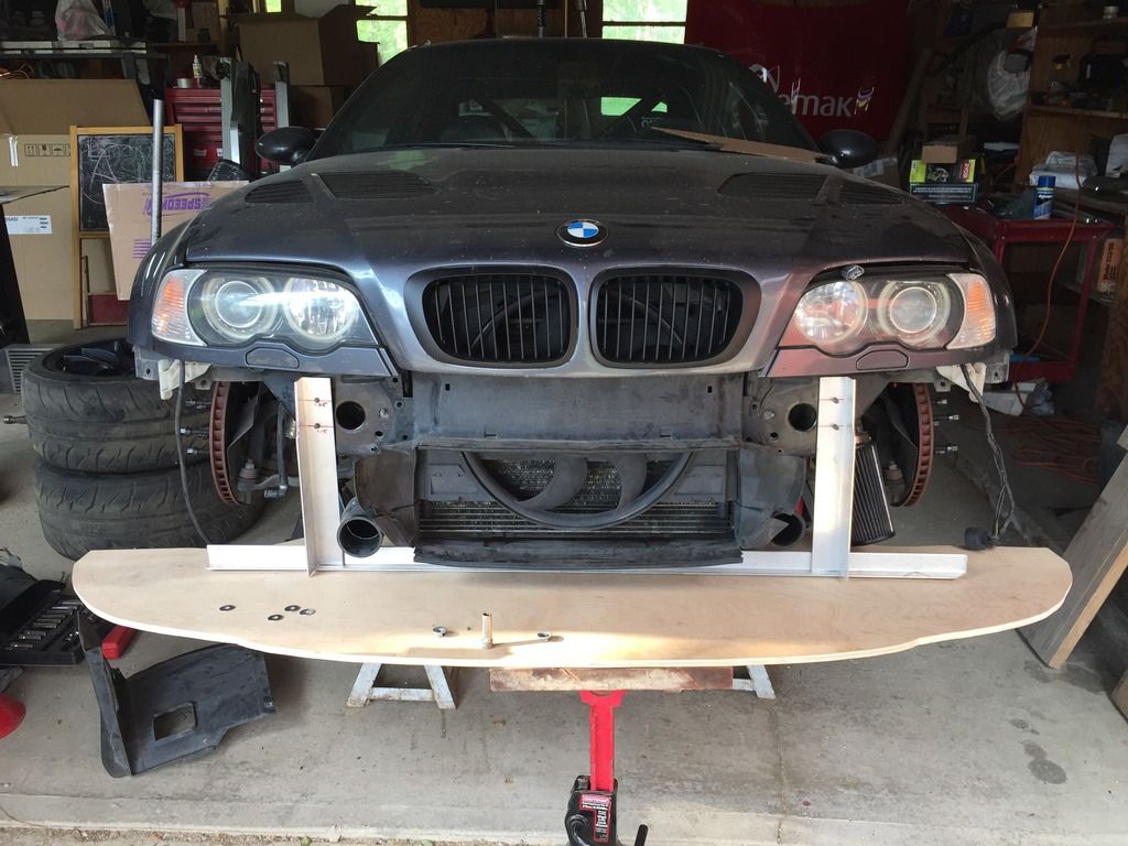
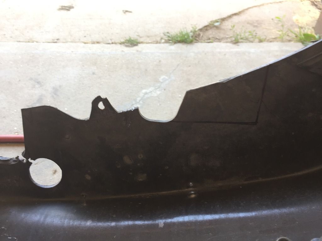
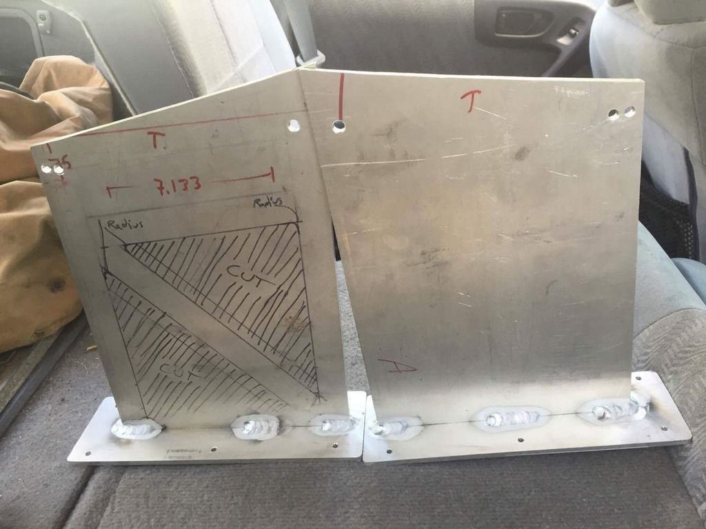
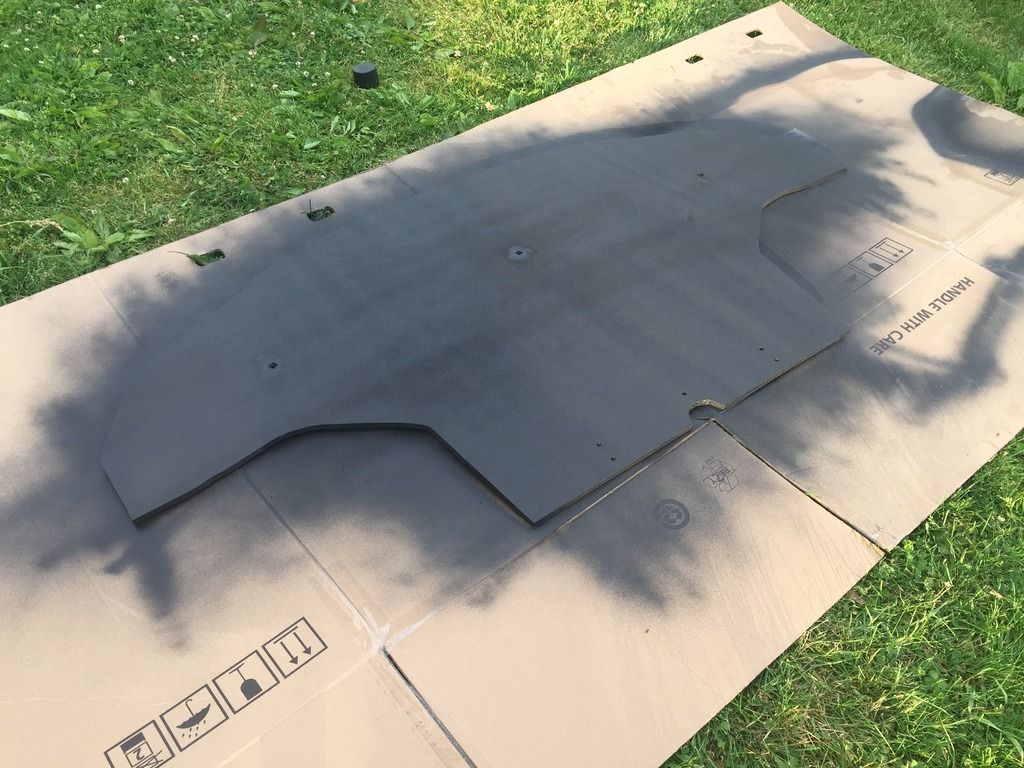
Alright, now how to make the car lighter? also, I need to paint the roll bar before it rusts.....Oh! I know:

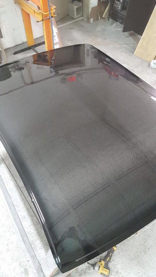
That project was scary, once you drill the first spot weld out there is no going back, it's actually not very difficult in hindsight just time consuming and nerve wracking. The various e46 forums have some pretty detailed how to's for this. I lost about 55lbs off the highest part of the car after adding up sunroof and all associated bits. Bonus, I gained an extra inch of helmet room after switching to a non sunroof headliner.

It certainly does give you a better angle for painting the roll bar though!

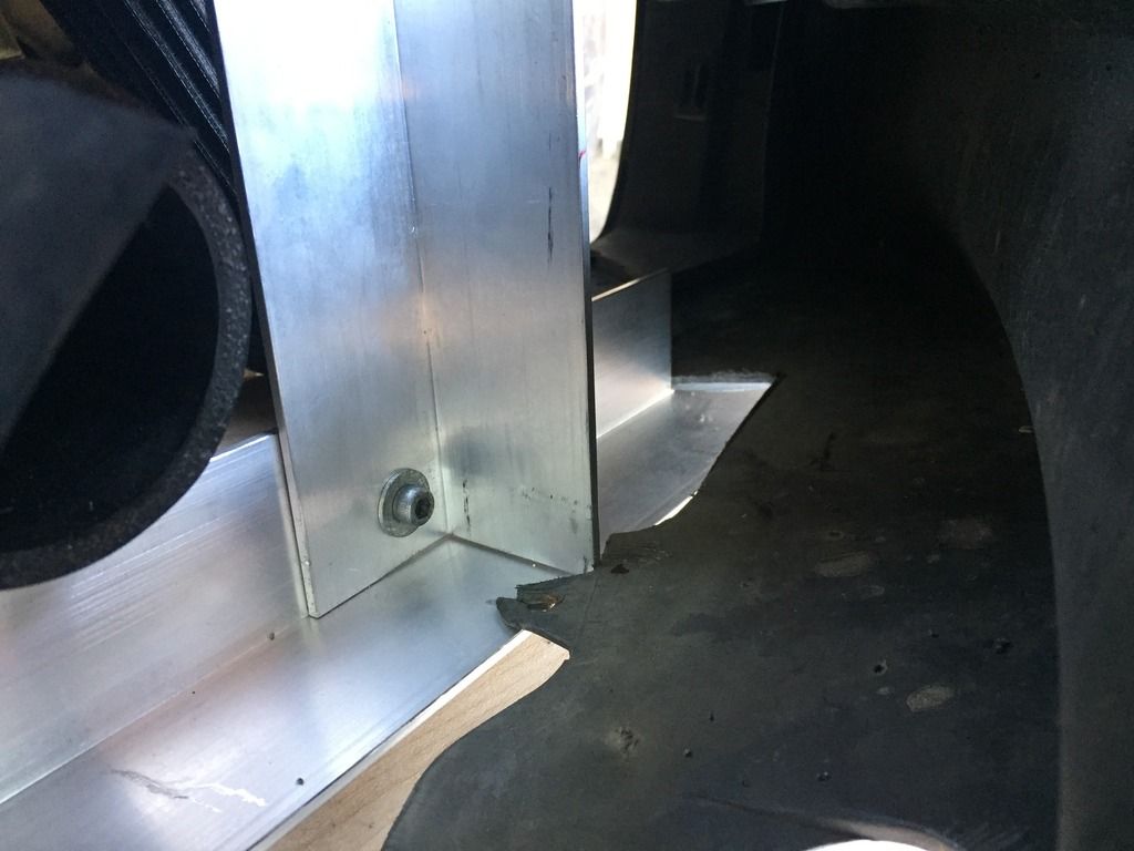
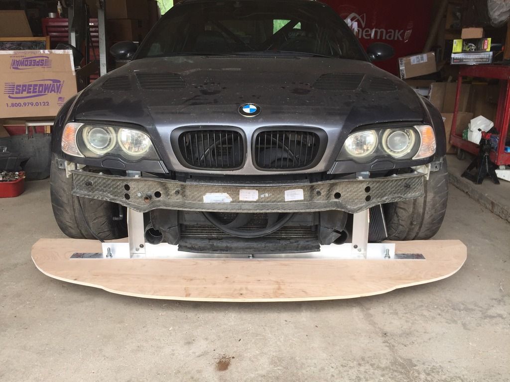
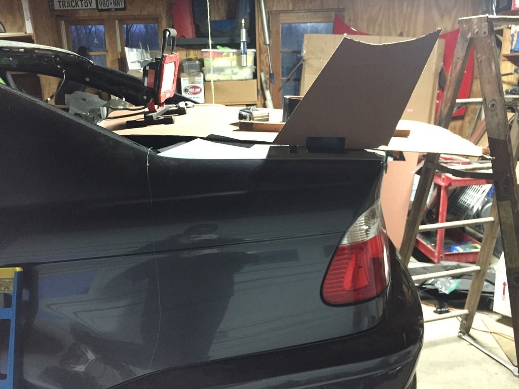
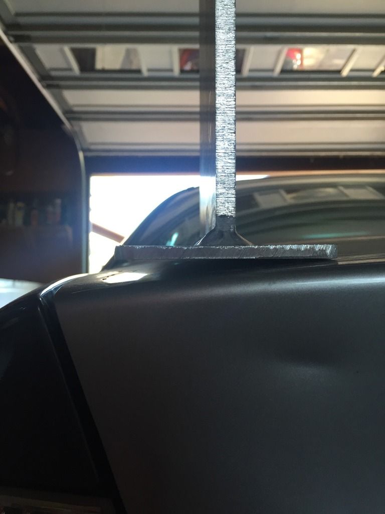
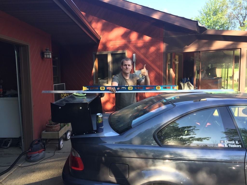
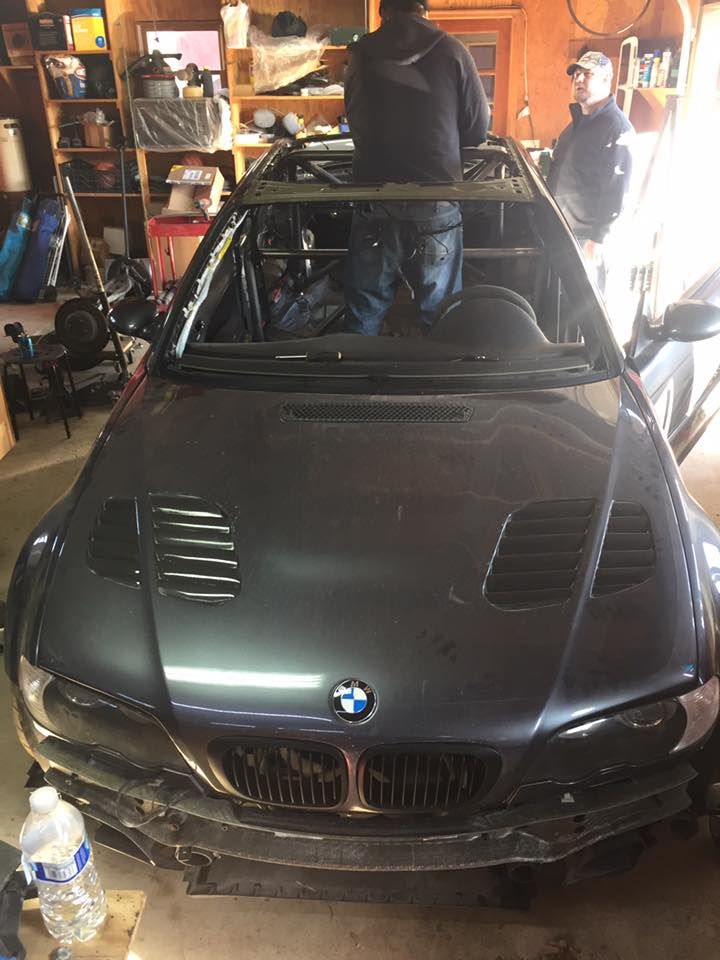
The trickiest part of gluing in the new roof was finding enough clamps....and figuring out how to hold the sides down, we had to improvise with a 2x8:

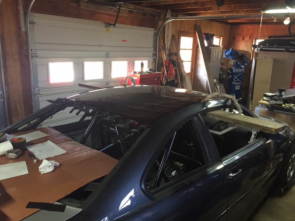
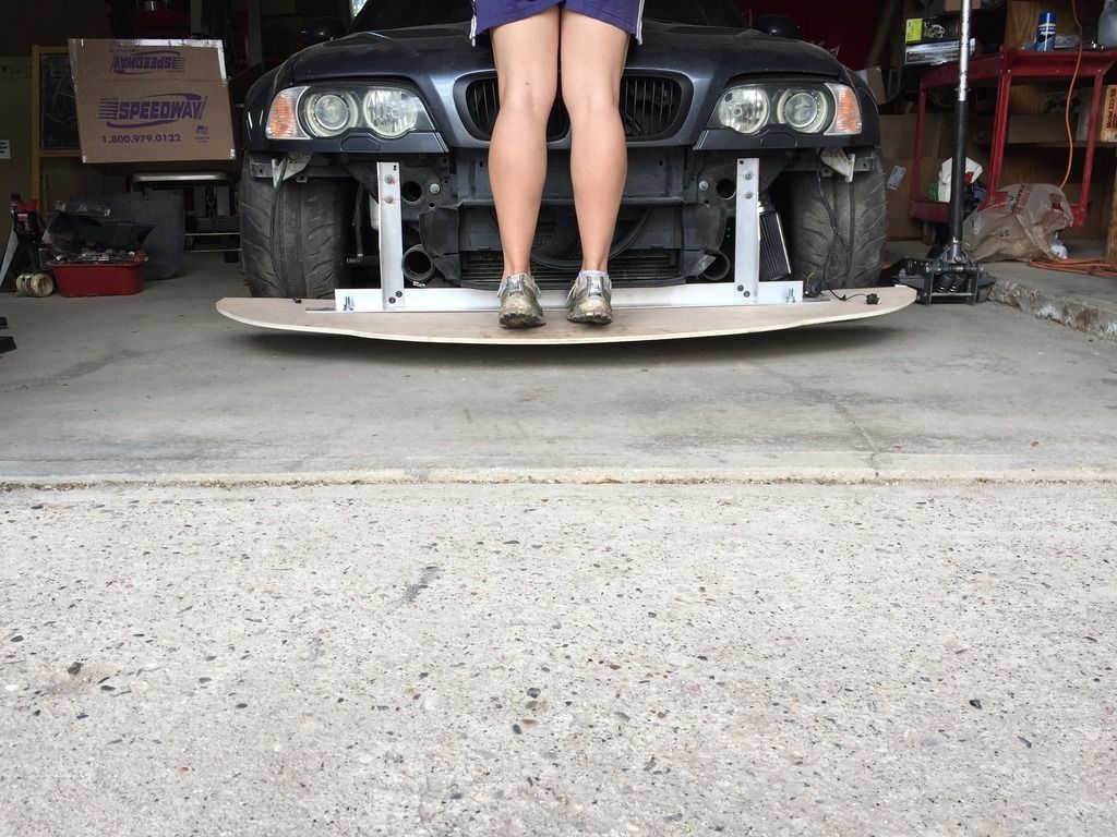
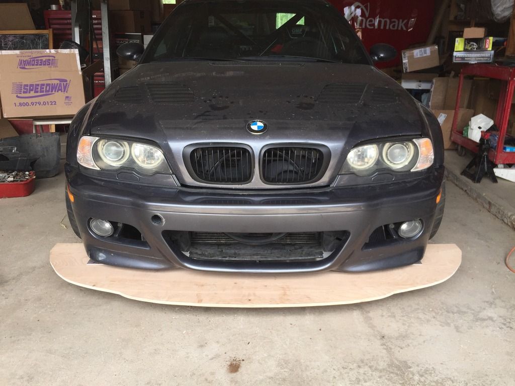
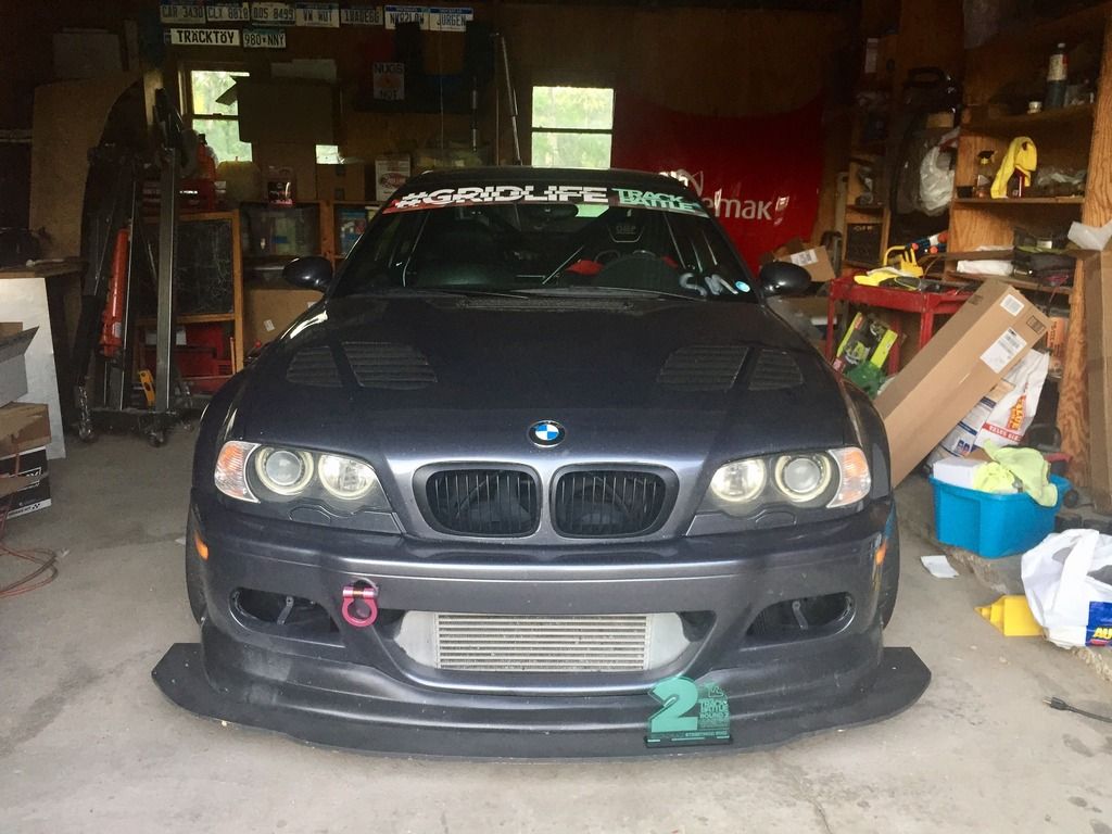
This was about the moment in the process where it started looking like a complete car again and I had confidence it would run again:

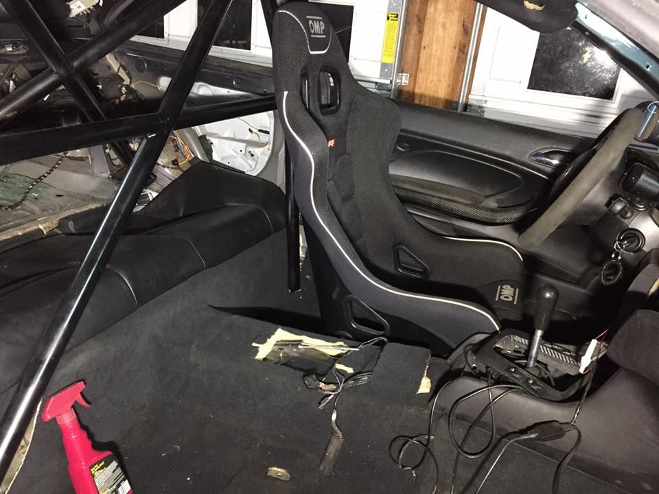
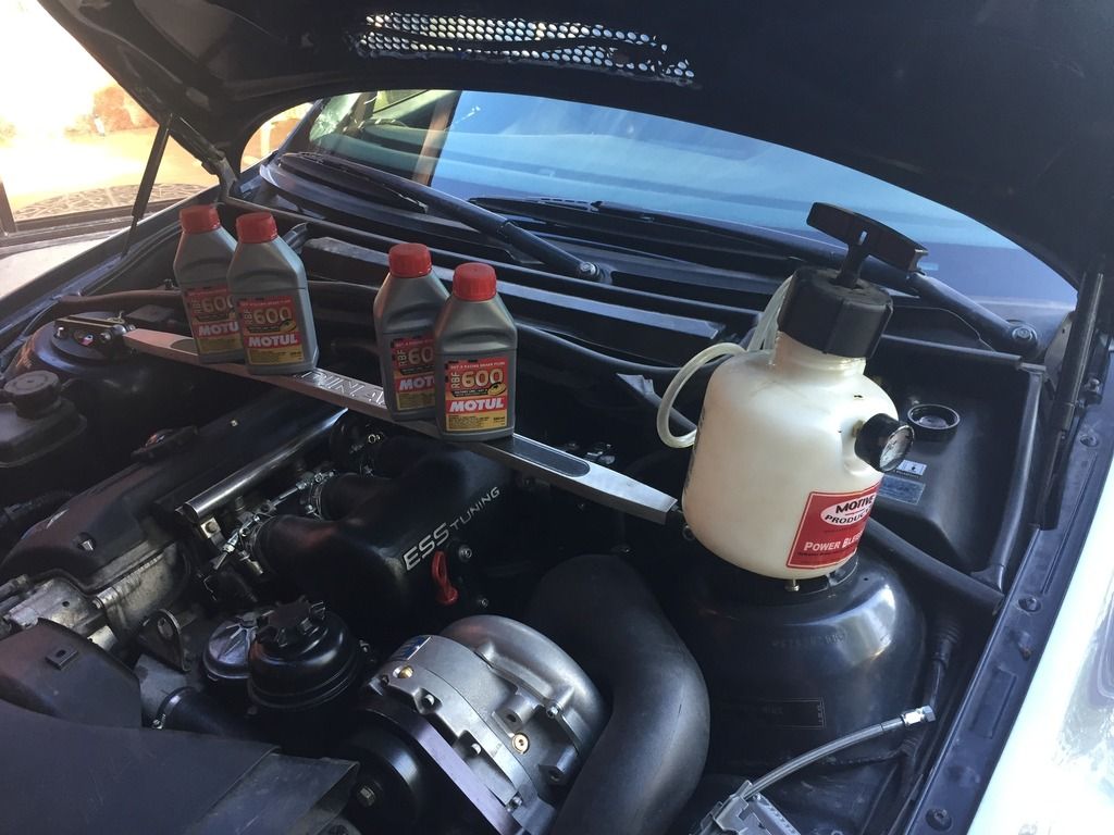
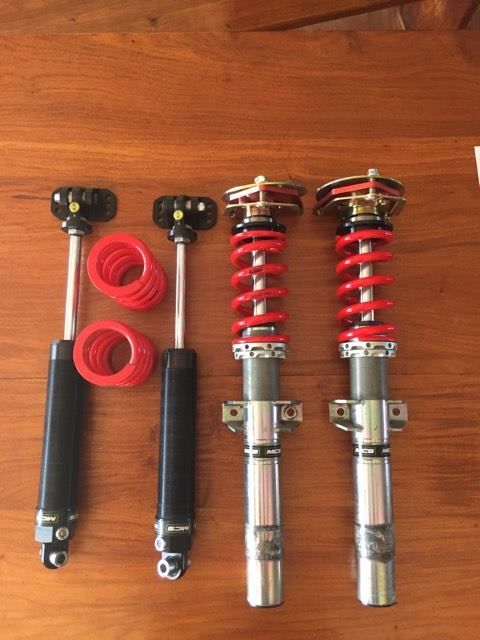
One last winter upgrade before the maiden spring voyage. My friend Matt (who competed in One Lap with me) decided to upgrade to Remote Reservoir shocks so I purchased his MCS 2 way non remote reservoir shocks to replace my dinan JRZ suspension setup:

I got those on my car just before we went to One Lap, dropped the car off for alignment and then ran out of time for a test drive! DOH!

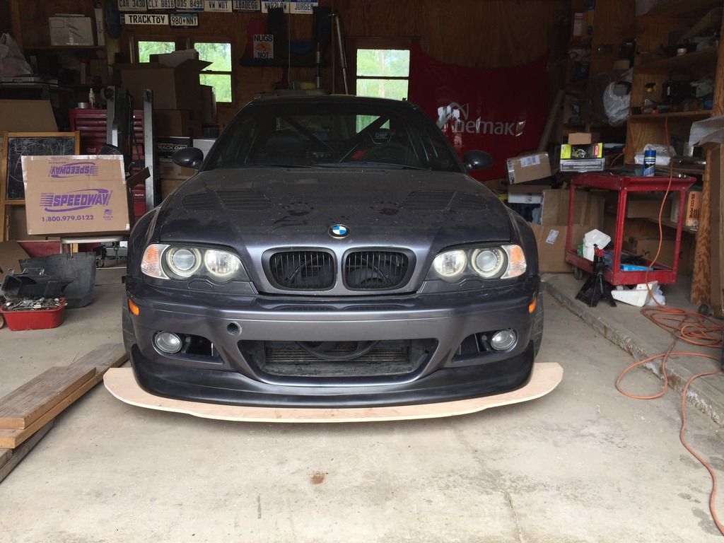
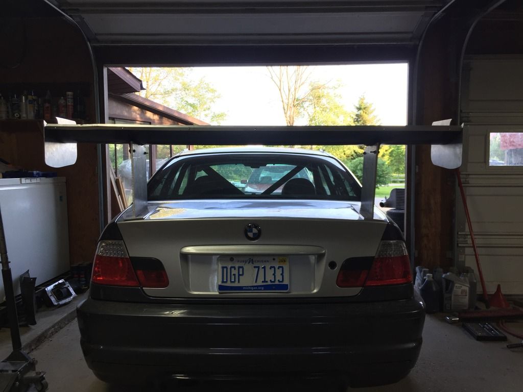
The day after we returned home I took it on a maiden voyage to visit our local clubs first auto-x of the season. The bimmerworld exhaust is too loud for me to run at this particular venue so shakedown would have to wait until a bit later but it made the trip to-from the track just fine:

All back together in 1 piece!

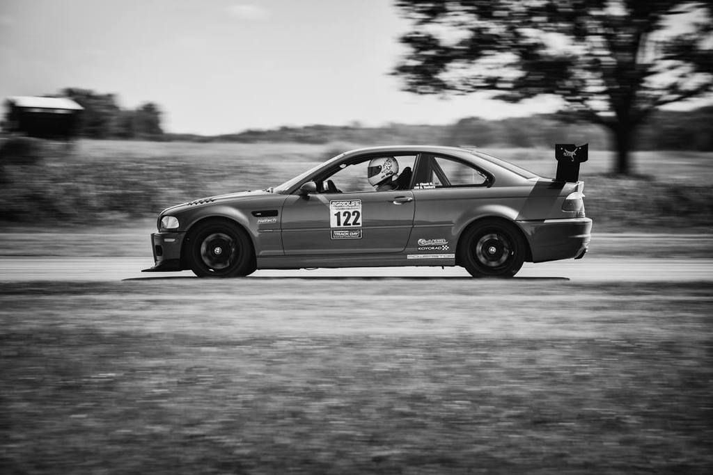
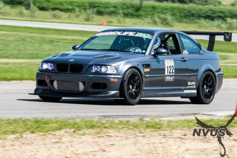
This past weekend was the 2nd local auto-x of the year at a venue with no noise concerns, the event was held at our local amusement park which makes for a cool back drop. I haven't seen any pictures of the car in action yet but hopefully some surface soon. So far I'm pretty happy with the changes, the car feels much like it did last year but a bit tighter and more responsive/agile.

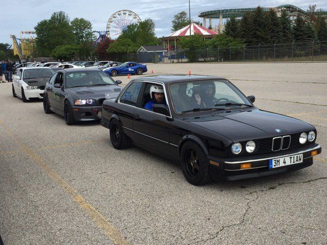
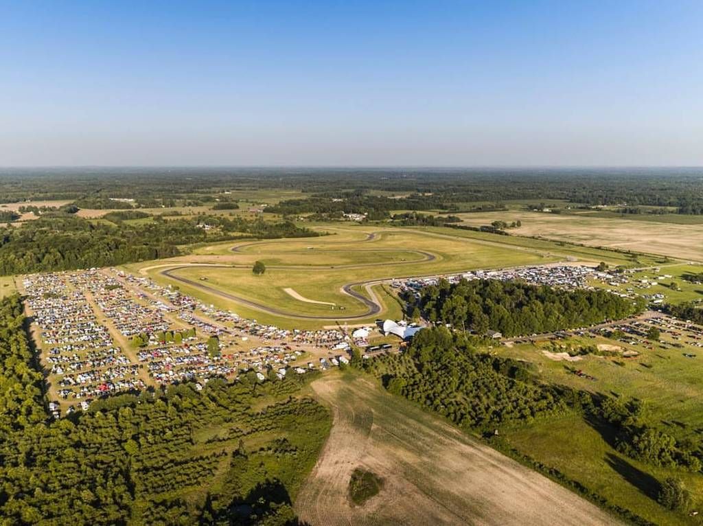
Our next event is in 2.5 weeks at Gingerman Raceway. Gridlife time attack. with over 130 cars signed up for time attack it's one of the biggest time trial events in the midwest. This event also includes exhibition drifting, a car show, hpde sessions and a music festival in the evenings. Over 5000 people turn up and it's pretty surreal at the grassroots level to have turns/straights filled with cheering spectators while you're driving.

I've got a few things I want to finish on the car before then and now that I've officially started a build thread hopefully that reminds/motivates me to take more/better photos.

I have some more photos of the above projects but was trying to condense as much as possible as I know I have a tendency to ramble on.

759NRNG
759NRNG Reader
5/25/17 9:12 a.m.

There are few Bimmers that actually get my juices flowing (3.5CSL Daytona), yours happens to be one that does.....coming from a CTS-V (2ndG) owner Following along here boss...

klodkrawler05
klodkrawler05 Reader
5/30/17 8:56 a.m.

Spent the weekend working on something entirely new to me. It's refreshing to mess around with new clean things, after banging away in the garage I was hardly any dirtier than when I started.

Step 1: find large cardboard (with an enthusiastic helper):

Step 2: put cardboard under car and plot points using plumb bob:

Step 3: (this was invaluable later) make square corners of known measurement:

note: in my case class rules state the splitter must extend no more than 5" from bodywork as viewed from above. I wanted straight ends on the splitter so I arbitrarily chose 3" wide from the rear corner of the bumper and then went straight forward from there until I hit the 5" mark, that resulted in the square corners seen above.

Step 4: cutout cardboard template:

Step 5: transfer cardboard template to large sheet of paper and find center based off square edges:

Step 6: fold in half, pick the side you like better, cutout template while folded in half, then transfer to your plywood:

Step 7: cutout plywood, sand edges etc:

Step 8: scratch head, how to attach, under the car we go! the stock undertray attaches to a pretty beefy aluminum plate, it uses those stupid speed clips for threads but there must be a better way, there is! enter rivnuts, this was my first time using them successfully (proper install tool helps a ton here) here you can see the rivnut conversion in progress, so rear of splitter will be held on with 3 M8 bolts:

Step 9: bolt back of splitter on and use jackstands plus wood scraps to set front height you can also see the pockets I had to notch out to allow the brake rotors to clear the splitter:

I'm adding an ebay lip to the car to make for a flat surface for the splitter, so how that lined up basically set the nose height of the splitter:

Step 10: With splitter in place roughly, trace wheel well openings, remove splitter and cut out here you see the final shape, My first set of holes for rear attachment wound up having the splitter more than 5" forward so I made a 2nd set and notched the splitter to clear the jacking pad:

Step 11: time to start working on the front mount, I'm skipping lots of cardboard aided design, head scratching and failed ideas for working around the intercooler piping here and moving straight to what I decided to do which is similar to some off the shelf options but with a twist. The OEM crash beam bolts to the frame horns and has these funky metal spacers glued to the back of it, perfect lots chop some of that off:

Step 12: Vertical support fab: The shape of the crash beam gives me some space to work with but not quite as much space as my 2" aluminum angle takes up, a little trimming and a couple holes drilled later I have this:

Step 13: Put crash beam back in place and check clearances and fitment several more times, then create mirror image for the other side:

With the extra angle leftover you can start to see where I'm heading here:

Step 14: After lots more head scratching it was decided to modify the bumper slightly:

Peeking through the bumper opening you can get an idea of why the bumper was modified (I ultimately wound up cutting a notch with the circular saw for the bumper to slide into the vertical upright as well but forgot to grab a picture of that. This turned out to be surprisingly helpful as the bumper lines up into the splitter frame before it engages any of the spots where it clips into the crash beam so now I can simply line those up and clip the bumper into place

Step 15: Not shown is the process of adding 3 1/2" diameter carriage bolts through the splitter and framework.

Step 16: This according to the internet is the most critical step, if someone can't stand on the splitter your work was for naught. I'm not sure I buy that a plywood plank can generate so much force that it will have over 100lbs in a downforce point load as this simulates but regardless, I tried it, for science. SWMBO graciously posed as ballast while I photographed. Test Success!

Step 17: I called the splitter done and decided to do one more final test fit before removing splitter for sealing/painting. This also shows order of install/removal should service be needed:

Crash beam in place:

Bumper clipped onto crash beam:

Lip clipped onto bumper: (still need to sort how to attach this)

Checking angle, there is a 1" per 3" rake to the splitter so hopefully some meaningful downforce will be generated from below:

So that's my progress! I know a few of the GRM One Lappers were talking about splitters so perhaps this will be helpful. I was able to build this entirely with supplies from the hardware store. I still have some finishing to do on it but it seems as though it should work!

conesare2seconds
conesare2seconds Dork
5/30/17 9:02 a.m.

Great post and pics. Thank you for sharing.

mazdeuce
mazdeuce MegaDork
5/30/17 9:36 a.m.

That was very helpful and I'm sending it off to the Civic owner right now. We may have 1/3 your power, but we still need downforce, right?

klodkrawler05
klodkrawler05 Reader
5/30/17 9:43 a.m.

If nothing else it might result in a drag reduction which is even more helpful at 1/3 the power right?

759NRNG
759NRNG Reader
5/30/17 9:43 a.m.

Is having too much downforce a possibility here??

mazdeuce
mazdeuce MegaDork
5/30/17 9:51 a.m.

In reply to klodkrawler05:

Absolutely. You could feel us reaching a drag limited speed pretty close to 120. Acceleration above 100 or so was pretty difficult and any help there would be significant.

klodkrawler05
klodkrawler05 Reader
5/30/17 10:06 a.m.
759NRNG wrote: Is having too much downforce a possibility here??

I have wondered that myself but figured it's easier to chop some off than add some on so I'm starting with the max allowed by the rules.

Folks smarter on this topic than me say that no, the front splitter at max rules width shouldn't overpower the rear aero.

There is a part 2 to the work I did this weekend but I haven't had time to type it all up yet.

here's a sneak peek:

sleepyhead
sleepyhead Reader
5/30/17 12:34 p.m.
klodkrawler05 wrote: If nothing else it might result in a drag reduction which is even more helpful at 1/3 the power right?

well, recall the civic is FWD... so I think generally the thinking is to get "all the front end aero" you can get.

Also, based on this study I found while poking around to help Tom1200, a splitter should see a drag reduction of 10% to 20% on a miata (ballpark figures).

And yeah, I agree that the GridLife rules will mean you'll be front-end limited compared to rear. Although, keep in mind that tuning elements of the rear defuser/wing/gurneys can lead to increases in front end aero now that you've got the splitter.

sleepyhead
sleepyhead Reader
5/30/17 1:16 p.m.
klodkrawler05 wrote: Step 16: This according to the internet is the most critical step, if someone can't stand on the splitter your work was for naught. I'm not sure I buy that a plywood plank can generate so much force that it will have over 100lbs in a downforce point load as this simulates but regardless, I tried it, for science. SWMBO graciously posed as ballast while I photographed. Test Success!

Rough napkin calculation (assuming my link before as a ballpark for Cl of 0.3): 1/2 * rho * S * Cl * V^2 = L

Guesses: Top speed of 140mph (205ft/sec), Splitter dimensions of 5.5ft width, 2ft depth, say 60%taper thus, 'splitter area' of 8.8sqft.

L = 0.5 * .002377 * 8.8 * 0.3 * (205^2) = 132lbf

so, 70lbs in the center isn't... out of the realm, which means you've got an factor of safety of nearly 2.

I might be wrong, have to think through the FBD/force vectors (not my strong suit), but the extra "depth" of the vertical "L" bracket below the part you trimmed back for the crash beam is 'dead weight'. The minimum height of the trimmed section will be your 'moment'/bending limitation. Although, cutting holes in the webbing towards the bottom might be easier/safer way of trimming that weight, if you are so inclined.

klodkrawler05
klodkrawler05 Reader
5/30/17 4:17 p.m.
sleepyhead wrote:
klodkrawler05 wrote: Step 16: This according to the internet is the most critical step, if someone can't stand on the splitter your work was for naught. I'm not sure I buy that a plywood plank can generate so much force that it will have over 100lbs in a downforce point load as this simulates but regardless, I tried it, for science. SWMBO graciously posed as ballast while I photographed. Test Success!
Rough napkin calculation (assuming my link before as a ballpark for Cl of 0.3): 1/2 * rho * S * Cl * V^2 = L Guesses: Top speed of 140mph (205ft/sec), Splitter dimensions of 5.5ft width, 2ft depth, say 60%taper thus, 'splitter area' of 8.8sqft. L = 0.5 * .002377 * 8.8 * 0.3 * (205^2) = 132lbf so, 70lbs in the center isn't... out of the realm, which means you've got an factor of safety of nearly 2. I might be wrong, have to think through the FBD/force vectors (not my strong suit), but the extra "depth" of the vertical "L" bracket below the part you trimmed back for the crash beam is 'dead weight'. The minimum height of the trimmed section will be your 'moment'/bending limitation. Although, cutting holes in the webbing towards the bottom might be easier/safer way of trimming that weight, if you are so inclined.

OOO interesting, calculation data saved! on that note, I was thinking you are indeed correct, I was thinking I'd toss that frame into a Catia simulation and see what happens. If that does indeed prove to be the case (I think you are correct I had already contemplated whacking the whole thing or drilling speed holes because fancy) I may perhaps do that after the first event/shake down of the aero.

Alternatively, if the setup proves weak, simply measuring better would've allowed me to keep all but maybe 1/8" of that vertical L if I had simply moved the vertical supports outboard about 1/2" to better clear the crash beam.

sleepyhead
sleepyhead Reader
5/30/17 6:43 p.m.

.

klodkrawler05 wrote:

OOO interesting, calculation data saved! on that note, I was thinking you are indeed correct, I was thinking I'd toss that frame into a Catia simulation and see what happens. [... ...]

Alternatively, if the setup proves weak, simply measuring better would've allowed me to keep all but maybe 1/8" of that vertical L if I had simply moved the vertical supports outboard about 1/2" to better clear the crash beam.

I'll note for future readers, and Aero persons, that traditionally that equation is given as
L = 1/2 * rho * V^2 * S * Cl
I'm using that alternate format because it's a little less confusing in the forum's text.

I don't know what's commonly available at the Stores of Hardware, nor how easy it is to drop into Catia... but you might consider box section for the verticals instead of "L". I'd think you'd be able to get away with smaller dimensions for the same strength that way, as long as you're careful to not over-tighten the fasteners and crush the box section

klodkrawler05
klodkrawler05 Reader
5/31/17 7:51 a.m.

Using the angle was purely out of convenience as it was the closest thing the hardware store had the moment of to the thickness of the metal spacers behind the crash beam.

My wing upright material was all "drops" that came from a local aluminum supplier all told I got about 30lbs of aluminum to mess with different wing support designs for the same price I paid for that single piece of angle from Home Depot Racing

That said, the HDR option was still far cheaper than this option which Bimmerworld will sell you for $300:

Hardmotorsports makes a cheaper alternative but I didn't like theirs from the standpoint of it potentially loosening and lowering the front of the splitter at undesirable moments:

klodkrawler05
klodkrawler05 Reader
6/1/17 10:07 a.m.

Alright, moving onto the rear of the car.

I bought a used bimmerworld race wing that was pretty well abused for what I thought was a good deal. What arrived was simply a carbon wing element.

Alright, well the helpful folks at bimmerworld were happy to sell me a new pair of the brackets that mount to the bottom of the wing, some new rivets had those installed quickly.

Next was tackling the end plates. I figured since I was already going to have to cut chips, might as well make something fancy. I found a picture of the newest Bimmerworld Ultralight GT wing, and roughly copied those (photo shows further along in process.

After that I moved back to my favorite kind of CAD, these turned out far nicer looking than my first revision metal bits will. This is partially due to time constraints, partially due to rule restraints, this swooped back design I wanted to utilize wrapping down the back of the trunk mounts the wing too far rearward to meet the "all aero within 5" of original silhouette as viewed from above" rule. Fortunately, many event's don't have such a rule so I will likely fab a set of this style anyways for those events.

Then was time to cut some metal and stack it on the car to see how everything fit, overall it looked pretty good, the shape is simple and likely far overkill for the force this wing will generate but I'd rather go that route than have a wing come loose on track.

A friend welded them together for me since that is a skill I sorely lack. I think they came out nice:

Doh! I was reminded why I typically try not to work on cars late at night after a long day of work, silly things get overlooked. during the above mockup it seemed like things fit all hunky dory. But I hadn't peered down the wing uprights, once welded that resulted in the uprights being about 7 degrees off from sitting flush on the trunk!

So that's where we got last night, I did some reading, checked some reference books and the all knowing google, armed with 5 minutes of research we now plan to delve into the world of bending 6061-t6 aluminum. Thankfully I still have a fair bit of scrap left over from the uprights as the pieces I ordered where about 10" longer than needed but not quite so long that I could make 2 from one piece. I'm planning to test several methods from bending over a large radius to heating and then bending in a friends brake. I'm hopeful since I need very little angle that I can get something to work well enough to use these uprights for the first event next weekend.

mazdeuce
mazdeuce MegaDork
6/1/17 10:16 a.m.

When we were hanging out last time there was talk of using a wicker on the trunk to affect airflow off the car making the wing more effective. I think I maybe understood half of that. Anyone care to explain?

klodkrawler05
klodkrawler05 Reader
6/1/17 10:46 a.m.

I have very little understanding of it myself but I think it's supposed to function much like a gurney flap on a wing (which I also barely understand)

It seems to be en vogue in the time attack world right now (and most be working) as the 2 fastest cars at the last GTA event had one:

sleepyhead
sleepyhead Reader
6/1/17 11:09 a.m.
mazdeuce wrote: When we were hanging out last time there was talk of using a wicker on the trunk to affect airflow off the car making the wing more effective. I think I maybe understood half of that. Anyone care to explain?

I think that means me. And I'm probably going to have to draw some pictures.... and/or hack some up in paint.

But you can get started poking around here, here, here, and cruising through this playlist of some tuft testing of a '3D ARC' wing on a FF Daytona Coupe.

sleepyhead
sleepyhead Reader
6/1/17 11:21 a.m.

a gurney on the back edge of a trunk is still a gurney, just like at the end of a wing section... since after all, a car is just a really badly shaped wing section

only time it isn't, is if it's at the front end of a wing section, and then it'd more probably be called a Krueger Flap.

the gist is that the "angle of attack" at the front of the wing will be some partial amount of the angle of the rear window. But as you get out to the tip of the wing, it will be closer to "free stream" (the Daytona Coupe is an especially vivid example of this, since the wing is mounted over the angled rear window, whereas most cars the wing is on the trunk which is closer to 'freestream', i.e. 0deg).

if you put a gurney on the trailing edge of the trunk (say, in the center) it will make the trunk 'look' taller, so the flow will get closer to 'freestream' to match the outer end. It'll also create a bigger low pressure zone just behind it which will help pull more air out of a diffuser if present (and well executed)... which can actually increase front end downforce.

one caveat to all this being that the on the sides of the cockpit will get pulled in to the center as well... so there's some 'cross-span' flow things going on as well, which complicates the above.

klodkrawler05
klodkrawler05 Reader
6/14/17 8:16 a.m.

Well I've gotta catch up on 2 weeks worth of going's on with the car so I'll try not to skip much.

After the faux pas with the wing mounts we got to learn all about how to bend 5/16 thick 6061 aluminum without cracking it, took the approach of making 3 small bends per upright as there was no tooling readily available to put a large radius bend. it worked well but I didn't take pictures.

Next up was making things look pretty before final assembly. I wanted to powdercoat the aluminum bits so they'd hold up better but we didn't have time so black rattle can it is:

for the splitter I copied Matt and used truck bed liner. I sealed the wood first using some random deck sealer we had left over at the house from previous owners. That turned out to be a mistake as it left a waxy residue and the bed liner is already chipping off.

While I was waiting for paint to dry I started messing around with the Race Capture Pro mk3. So far this thing has been nothing but a headache. lap timing wise it seems to work ok but my whole goal was to be able to log CANBUS stuff and despite it recognizing channels it won't let me add them and then display them. To be fair electronics aren't my strong suit, I'm an apple user normally and I've not spent more than 10 minutes on this at any one time. It's certainly not plug and drive like my old traqmate was though.

After paint was dry it was time to mount everything and make sure I was below level and legal for Gridlife on my wing, yup!

I liked this sticker placement:

Splitter Mounted:

Haven't bled the brakes since last year, nothing exciting but I figured I'd show my setup, this makes brakes such an easy mess free 1 person job:

This Schwaben brake fluid bottle is really the key, the special nipple on the end fits over the bleeder screw snuggly and makes for hands free fluid capture:

When the racecar is done ahead of time might as well start putting some street miles on it to prepare for One lap right? Parked next to my coworkers schoolbus wrx:

And now off to Gridlife! Reunited with Matt's M3 (that we took on One Lap this year)

Started off with shocks set as they were last year and had some terminal understeer. Knocked a bunch of the front compression out and the car was superb for Friday Practice. Coming into the pits for a shock adjustment:

Saturday morning was clear and cool low 70's and looked to be the ideal session for fast laps as the rest of the weekend was supposed to be 90+ degrees. Unfortunately this is where I learned about boost leak testing. The couplers holding the intake manifold on popped off the ITB's. Upon fixing this issue we learned the previous owner had mix and matched various size clamps and some of them didn't get tight enough, they were snug but not tight. Why this became an issue this morning instead instead of the previous 2 track days and 3 auto-x event's I've done so far I don't know.

All fixed and ready to go:

except we forgot to plug the TPMS sensor back in after we finished tightening the clamps....and we learned that the linkage hits the stud of the T-Bolt clamps if they aren't situated exactly just so. Thankfully there was a BMW whiz there to help us sort through those issues Saturday afternoon in time for the final session on Saturday.

Track conditions still seemed to be quite poor. During One Lap Matt and I were both able to turn 1:40 lap times at Gingerman, in his car Matt was stuck in the 1:42's on the Conti's so he switched to sticker re71's and managed to drop down to a low 1:41. In my car I was able to run a 1:40.9 before the car started getting dangerously hot and I called it good.

Sunday morning was about the last chance to go fast but probably not as fast as the missed Saturday morning session. Double checked all the boost connections were attached and headed out! I managed to slightly better my time with a 1:40.4 which is almost exactly 2 seconds faster than I went in this car last fall with much better conditions. So I'd say the modifications have helped although it's still tough to get a great barometer of how much they've helped as the track felt quite dusty.

Since the weather continued getting warmer I knew that my driving wasn't going to be able to get me any faster lap time. So I opted to try to learn something and put Tom O'Gorman in the car

Timing him by stopwatch on his warm up lap he appeared to be on pace to run with my best lap time "feeling out the car" on a track he'd never been to until the day before. He crossed the start line and began his hot lap and it was pretty awesome to see, my wife and brother in law both said he was carrying noticeably more speed through corners. As he turned onto the long back straight we could suddenly tell something was wrong, his speed dropped dramatically and he let several cars pull past him before exiting the track. When he got to us he said the car felt like it suddenly stopped making power so he brought it in. The manifold had once again popped off and this time there was a small tear in one of the boots. With no spare boots I had no choice but to call it a day. I knew I wouldn't go faster but I was disappointed I wouldn't get to see a lap time from Tom in the car. (note to self, bring extra couplers and clamps to one lap)

All said and done the car drove itself onto the trailer (albeit without boost) and was faster than last time I was at the track so I called that a success. It turns out my time was good enough for 2nd place in class and 25th overall! So I'm calling this event a great success.

The next Gridlife takes place at Autobahn Country club in 3 weeks so I've got a few issues to fix before then!

1) The brakes were pretty soft, the stoptech street pads certainly aren't up to the speed this car can generate so I'll replace those with some PFC08's like we ran on Matt's car.

2) The car can only do 2 laps at best before oil temps approach 300 and coolant starts climbing past the halfway mark so I've ordered a bigger oil cooler and radiator stack to hopefully alleviate that.

3) Fix the boost leaks, talking to the RS guys they dislike t-bolts because it can pinch the boot oddly vs normal hose clamps, they run Breeze brand worm drive clamps which are rated for 150 ft/lbs of torque on the worm gear so I'm going to try those out (not at that much torque) and they noted lots of oily residue on the ITB couplers and the ITB's themselves and pointed out both should be extremely clean before I reinstall to prevent slipping more easily. They also mentioned the couplers getting soft over time so either new couplers or using hairspray when putting the couplers on to help prevent sliding.

klodkrawler05
klodkrawler05 Reader
6/14/17 1:05 p.m.

Just found this picture and had to share it. The amount of people that show up to spectate, drive, race, drift for #gridlife is unlike any other event I've been to for the Amateur level.

Most of those tree's are packed full of the lucky folks who got to the track early enough to secure a coveted shade spot:

xflowgolf
xflowgolf Dork
6/15/17 7:44 a.m.

proud of you.

mazdeuce
mazdeuce MegaDork
6/16/17 8:56 a.m.

Now that you're getting it sorted, how much faster is this car than Matt's?
And that crowd shot is absolutely crazy for a road course event. They're doing something very tight on the organization level.

klodkrawler05
klodkrawler05 Reader
6/16/17 12:27 p.m.

At Gridlife I beat him by about .5 seconds. Bare in mind he's the faster driver so that's somewhat telling.

The biggest difference when we played cat and mouse was that he can brake at the 2nd to last brake marker, I'm squeezing the brakes 2 markers earlier hoping the stoptech street pads will woah me down in time. We get through the turn about the same (not shocking given identical suspension/tires)
And then I reel back in the distance lost in braking down the next straight.

I ordered the bits to duplicate his braking setup so should be able to put some more time up on his car at the next event but we'll see. I think with brake improvements and a car that can do a full 3 hot laps it's not unreasonable to say this car in current form is about 1.5-2 seconds per lap faster than Matts.

docwyte
docwyte Dork
6/16/17 9:37 p.m.

Street pads are totally inadequate for your car. You're nuts for going on track with them.

I had the 355 Stoptech BBK all the way round on my VF Supercharged E46 M3, with Hawk DTC70 pads. Phenomenal braking. Truly outstanding, I highly recommend it.

1 2 3

You'll need to log in to post.

Our Preferred Partners
W390SZ1EQs865vIAAPQXK7lkBtNBWqyFHqyd2GQaS8Ik4aEOsSqUdMvrGzhPNaEQ