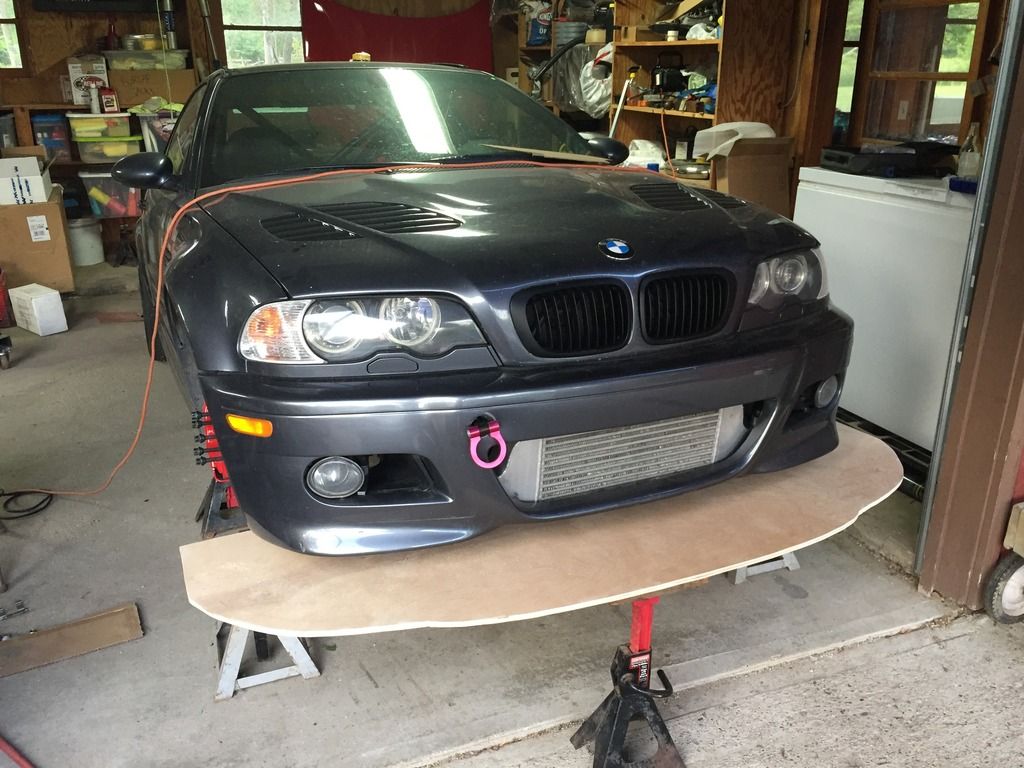
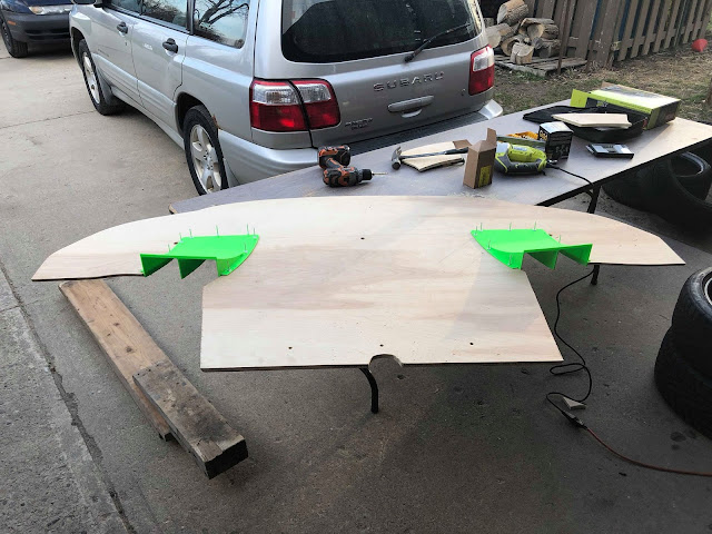
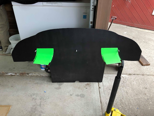
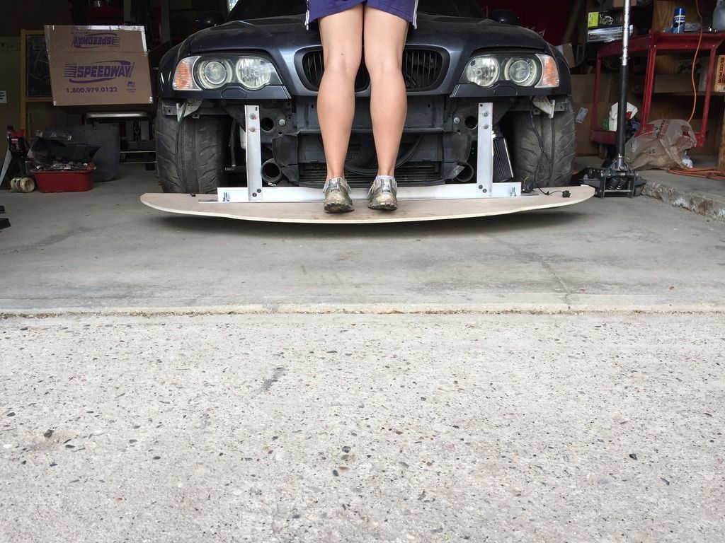
1 2 3 4 5
sleepyhead
sleepyhead HalfDork
2/26/18 9:25 a.m.
sleepyhead said:
klodkrawler05 wrote: Step 16: This according to the internet is the most critical step, if someone can't stand on the splitter your work was for naught. I'm not sure I buy that a plywood plank can generate so much force that it will have over 100lbs in a downforce point load as this simulates but regardless, I tried it, for science. SWMBO graciously posed as ballast while I photographed. Test Success!

Rough napkin calculation (assuming my link before as a ballpark for Cl of 0.3): 1/2 * rho * S * Cl * V^2 = L

Guesses: Top speed of 140mph (205ft/sec), Splitter dimensions of 5.5ft width, 2ft depth, say 60%taper thus, 'splitter area' of 8.8sqft.

L = 0.5 * .002377 * 8.8 * 0.3 * (205^2) = 132lbf

so, 70lbs in the center isn't... out of the realm, which means you've got an factor of safety of nearly 2.

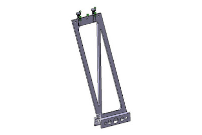
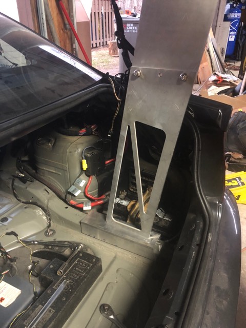
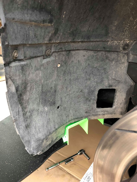
I might be wrong, have to think through the FBD/force vectors (not my strong suit), but the extra "depth" of the vertical "L" bracket below the part you trimmed back for the crash beam is 'dead weight'. The minimum height of the trimmed section will be your 'moment'/bending limitation. Although, cutting holes in the webbing towards the bottom might be easier/safer way of trimming that weight, if you are so inclined.

I thought I would pop in over here, and chime in that olaaf's second comment over here means my 0.3 Cl estimate is "in the ballpark"

w00t

alright, continue about your build

klodkrawler05
klodkrawler05 Reader
2/26/18 2:24 p.m.

ooo that is an excellent read! I have subscribed to try to learn some things.

Haven't made much progress on the car as I went back to school this fall but we've been slowly working on tweaks as time allows.

Since we expect the new wings to make more DF we started working on things for the front, I drew up these ducts and Matt tested out his 3D printer, for a rough draft I think they turned out ok.


We'll be pairing these with vented fenders to try to evacuate air from the front wheel wells as quickly as possible.


The first draft is roughly 11" x 11" x 2.5" and we have a left/right side.

klodkrawler05
klodkrawler05 Reader
3/19/18 1:22 p.m.

Well, the weather has finally turned for the better near us, it's time to revive this thread.

First up was working on a new wing mount for the GoodAero wing, since I was already seeing evidence of dents in the trunk from the old wing I will have to brace this wing to the chassis.

First up was a little CAD:

This design had some little swivel feet on top and the idea was when the trunk was shut the wing would be mounted directly above these feet so the load would transfer to the chassis, It should work but I decided it was overcomplicating a somewhat easy problem, since the only time I need to get into the trunk is to access the battery.

So revision 2 was born, it's a bit less fancy and has the area which will be in the airstream solid for better aerodynamics. 

I printed some 1:1 scale copies of these and transposed that into wood so that I could check my measurements and verify the wing was going to be below the roof (per class rules)

I had alloted myself the entire day to mess with the car so once that was done I started brainstorming some other "free" improvements I could make to the car. Inspired by Tim's OLOA prep thread I started removing extraneous components. 

First to go was the trunk support structure. A tidy 7.5lb savings:

I found a bit of trim in the trunk and an additional amplifier that had somehow escaped removal last year, that netted me 3.9lbs

I pulled the door panels off to remove the last exploding bags, since I don't have a radio anyways, it seemed silly to leave 3 speakers behind each panel. another 4.7lbs!

The panel by itself still seemed rather portly so off with it's handle, I'd like to re-trim this at some point to make it more intentional but for now the 5.5lbs it shaved is the reward. 

Next up was the EVAP system, this massive box near the rear of the car houses 10lbs worth of emissions equipment plus a large bit of heat shield which is no longer needed. it also frees up a bunch of space under the car for a diffuser. 

The last thing I did was swap out the power heated fancy M3 passenger seat with a base model manual no option seat, this was good for 19lbs worth of savings. It's still nearly a 50lb seat but $/lb it was a more attractive option for my budget. 

Here's a photo of most of the junk that's no longer on the car. A few hours were good for 55 lbs worth of weight savings!

docwyte
docwyte SuperDork
3/19/18 3:43 p.m.

Too bad you don't have an E36, I'd be all over those BSW speakers!

klodkrawler05
klodkrawler05 Reader
3/20/18 6:18 a.m.

I was pleasantly surprised to find those hiding behind the door cards! I'm hoping I can use those to re-coop enough money for entry to another track day this year!

mazdeuce - Seth
mazdeuce - Seth Mod Squad
3/20/18 6:29 a.m.

Be sure to update us with pictures of those 3D printed pieces installed. I'm interested in seeing how it all looks and functions. 

klodkrawler05
klodkrawler05 Reader
3/20/18 11:23 a.m.

I absolutely will, Matt is doing some repair work on his printer now but in another week or two I should have some installed pics.

klodkrawler05
klodkrawler05 Reader
3/26/18 8:08 a.m.

Got a bit more work done this weekend. Only 2 weekends until the first Gridlife event of the season at Mid Ohio.

The wing mounts I drew up got laser cut by a friend:

They fit really well, mocking them up in the trunk they're pretty much perfect for maximum height allowed by the class. One unconsidered advantage to this setup is I could simply remake the top plate if I ever wanted to position the wing higher or further back for other classes/events.

I couldn't find any aluminum U-channel with the interior dimensions I needed but I did find some rectangle tube that would work, I used a bandsaw to cut the length and then a circular saw with a metal blade to cut off one end......unfortunately despite measuring and writing down the correct dimensions, I still managed to order the wrong size material. DOH!

So I re-ordered the correct size and will have to try this again.

I purchased the N15designs fender vents and worked on installing those. The fit is pretty good although it's definitely harder to put these on the compound curve of the fenders than the flat hood vents. I think they turned out pretty good and match the hood vent style pretty well despite the slight coating difference:


 There was still a little daylight left so I spent some time playing with the 3D printed diffuser tunnels I'm working on. I'll be making some tweaks to those hopefully this week.

You can also see the splitter after a season of abuse, most of the exposed truck bed coating has flaked off but overall it's held up quite well.

This is approximately 15 days on track, a half dozen autocross events and 3,000 street miles later. I think most of the coating is coming off due to the sealant I put on before painting (it has a waxy residue once dry) and the square edge results in the bed liner chipping easily.

I'm going to make a new one this week and will spray the bed liner onto the new one without any coating. I'm also going to borrow a friends router to see if a smoother corner edge will help rev2 last longer.

sleepyhead
sleepyhead Dork
3/26/18 11:00 a.m.

ah.. that makes more sense... I thought those were going to be canards

packaging with the brake cooling might be interesting.  I suspect you'd probably get more effect from doing that on the portion of the splitter outboard of the bumper, since it'll operate into a less compromised area... even with the added vents above the fenders... because those are exiting right into an area where the tires are shedding off air in the opposite direction.  So, I'd make sure you have a way to block those off easily/quickly between sessions.

If you round over the front edge of the splitter... make sure to round the bottom, not the top... that will most closely "mimic" and airfoil shape, If I'm Thinking Correctly

xflowgolf
xflowgolf Dork
3/26/18 12:31 p.m.

Don't know enough about aero but assume you did your homework.  Does it matter where the fender vents are located?  i.e. on top of the tire like yours vs. behind the tire as seen on a lot of other cars?  

Is the primary benefit for brake/tire cooling or does it improve aero efficiency somehow?  

klodkrawler05
klodkrawler05 Reader
3/26/18 12:47 p.m.

Good points all around, I hadn't considered the aerodynamic effects of rounding the edges of the splitter. I was going to round both edges simply to allow the paint to stick better. But maybe I'll try rounding just the bottom edge this time around. I'm still searching for a cheap way to measure changes in ride height at various speeds so I can calculate what if any downforce these changes are producing. moving the location of those splitter ducts is part of why I'd like to be able to test that. Perhaps a manometer would suffice to test where pressure differentials are greatest?

I haven't worried about brake cooling at this point as I haven't need any thus far. I was actually considering doing a test blocking off the front bumper openings to smooth the nose out a bit to see what happens.

Regarding the fender vents, I haven't cut up my fender liners yet so I was thinking to test for the first event I would try, no fender liners, with fender liners (which would effectively block off the vent) and with trimmed fender liner. By now I've heard multiple times not to build your car based on what professional racing does because they are often far more limited by the rules. Although, I have seen some cars where the entire top of the tire is exposed (like LMP1) would it be safe to assume those openings are for something different than airflow or are operating with a far more complex aero package than my simple plywood and sheetmetal?


sleepyhead
sleepyhead Dork
3/26/18 1:32 p.m.

In reply to klodkrawler05 :

re: LMP over-wheel holes...

search around on mulsannescorner.com (link to first "news mention") of the "Big Honking Holes" or "Big Honkin Holes".  I felt like there was a summary page about them on there, by it's not cropping up with a site search.

tl;dr
those holes are there with the big vertical "dorsal fin" to relieve high pressure around the wheels and reduce rear lift that was causing some cars back in 2008-2010 (?) that were taking off after getting loose which was creating a significant "lateral wind component" (i.e. Beta).  I think this was seen mainly in the Porsche Curves, iirc.  Thus, they are effectively, a rules mandated aero-safety device.  ymmv?


re: over fender vents
I'm a little doubtful that they'll be much of a help with the tunnels you have... just because that'd be a pretty massive turn to make without any other device to encourage/demand the air turn and go up.  Part of the reason, I think, for many time attack cars to go wide body is to create a "dead pocket" between the engine bay and the wheels/uprights to allow those tunnels to be more effective.

*if you do something outboard, make sure it's got a fence/tip-plate like your wing.  It'll help keep the flow aligned in the area, and not let errant side-ways flows to reduce their effectiveness.  Plus extending it up above the tunnel on the outside will help create a vortex that'll help suck out the tunnel, help the whole flowfield "jump and reattach" behind the front wheel opening.  If you had radiused/side-vents that vortex might also help evacuate the wheel well... but that'll be limited until that's done.

*I reserve the right for this to be corrected by stafford1500 or another more experienced aerodynamicist.

mazdeuce - Seth
mazdeuce - Seth Mod Squad
3/26/18 3:01 p.m.

Everything I read says closer to the track is better for splitters. One Lap cars need to survive roads so there's a practical limit there somewhere. Lots of OEM's deal with this by adding a flexible air dam. Chevy goes whole hog on the Volt and the part is low enough that it's a wear item. Is there any benefit to adding a flexible lip to the front edge of the splitter to reduce the gap? Clearly not perfect, but would it be better than a large splitter to track distance?

sleepyhead
sleepyhead Dork
3/26/18 4:09 p.m.

In reply to mazdeuce - Seth :

the chevy volt airdam is all about drag, and not about downforce.  as for it being "whole hog"... it's whole hog from the point of view of pork is cheap.  and making people buy plastic outside the warrantee period to maintain EPA mileage performance sounds like the kind of thing GM would do.

as for "taking something on"... keep in your mind's eye the fact that the bottom of the splitter is supposed to mimic the "upper surface" of an airfoil... sort of.  Part of the reason it's there is to extend forward the division between "flow going over the car, vs. air going under the car" (and to do so in a way that the flow is nicely aligned with "the flow direction")... this division being "true" mostly between the splitter and about the "front axle waterline"... or perhaps the "A pillar" area.  By pushing this point forward and down, you reduce drag because reasons.  The next job for the splitter to do is to act like the front wing on a formula car... but it usually has to do this all in the back half of the splitter.  So, dropping some kind of vertical surface between the splitter and the ground is akin to putting out "spoilers" like on sailplanes...

which are used to reduce lift, through the creation of turbulence (the complete opposite of what you're trying to do, on both counts).

I'd reckon the "Jack Olsen" approach of "bolt my splitter on after the transit" would probably be your best bet... especially when combined with a post-transit ride-height adjustment.

klodkrawler05
klodkrawler05 Reader
3/27/18 7:15 a.m.

Regarding splitters and transit, Matt and I are both between 4-5" between the ground and bottom of our splitter pending current tires bolted onto the cars. That held up pretty well over last years transit and the various other street driving we did.

Matt's is a bit different setup but my splitter rides an inch or so below the height of the bumper, and is free to flex upwards from roughly the mid point of the splitter forward. (a good reason not to use splitter struts on the front)

We have talked about lowering the nose of the car more and from a quick check (i.e. probably not totally accurate) it seems we could lower the car more without totally ruining our roll center. 

This picture shows it at it's mounted height (ebay lip goes on to seal up the gap between)

mazdeuce - Seth
mazdeuce - Seth Mod Squad
3/27/18 7:24 a.m.

In reply to sleepyhead :

Well, I'm as much about reducing drag as I am about creating downforce, so GM and I are on the same page. laugh I need to put the car on the lift, figure out my mounting points and just start experimenting. 

In reply to klodkrawler05 :

Mounting considerations have been high on my list of things to think about. I need to pull the front off the car and poke around. Incidentally, I reference this thread a LOT when I send people off to read about home made splitters. It's been a good teaching tool. 

klodkrawler05
klodkrawler05 Reader
3/27/18 8:52 a.m.

I'm glad it has been helpful for someone! I see so many horror stories of splitters ripping off the first time they're tested that I wanted to try showcasing how simple it can be to make something that holds up to abuse.

Giving more thought to a OLOA specific splitter, this would require some testing but. If you could attach the back edge to something solid like the subframe and then rather than my aluminum structure just behind the bumper you instead used steel cables to support the leading edge of the splitter (as shown below) 

So something like that, but, with upper eyelets that you can access with the bumper still on, perhaps more like this:

I'm imagining a pair of "transit cables" with caribiners on each end, these transit cables would be shorter than the on track cables (which could get left on the car the entire time)  so effectively you would clip on the transit cables and hinge the entire splitter upward resulting in more clearance for road hazards and such.

The splitter needs to remain sealed to the bumper of course but I'm imagining a typical home depot splitter skirt like below, you could have one mounted on the bumper and an identical one mounted on the splitter just a hair forward such that they slide behind one another when you lift the nose of the splitter for transit mode.


It might be overcomplicating what should be a fairly simple piece or it might be a great way to increase surface area of the splitter while ensuring it survives the transit.........I'm not sure which.

klodkrawler05
klodkrawler05 Reader
3/30/18 7:53 a.m.

Chipping away at it. Finally got the correct size rectangle tubing, Cut the bottom edge off and it seems like it'll work great!

For anyone who may be considering this style mount for an e46 I'll save you the legwork,

I used 3"x3" square tube with 1/8" thick wall.
Inside width is 2.75" (that's the important one that I messed up last time)
I cut these down to around 12" but any length longer than the upright is wide should work.

I did have to make some notches to clear the battery cable and the bracket, I'm not crazy about this so far because it means I'll have to unbolt the upright to get the battery bracket off. But I would likely have to remove the upright to get the battery out of the car anyways so perhaps it's not a big deal.

I'm hoping to get a friend to weld the uprights tonight and then I can finish the wing setup this weekend!


klodkrawler05
klodkrawler05 Reader
4/2/18 1:05 p.m.

Well, wrapped up the wing this weekend, no point posting a wall of text since it was mostly just drilling holes and bolting things together.

Now that we're all sick of seeing photos of the wing system (i'm sick of building it) here are finished photos.

The upper braces are 8mm threaded rod with 12mm OD carbon tube to hold the space:

mazdeuce - Seth
mazdeuce - Seth Mod Squad
4/2/18 1:07 p.m.

Is this still a future One Lap car? I'm not suggesting that you just made life difficult, but you sure didn't make packing any easier. Trailer? 

klodkrawler05
klodkrawler05 Reader
4/2/18 1:29 p.m.

Trailer for sure. Additionally I expect another revision before we do OLOA next year. Perhaps like my original thought of having 2 feet on the bottom side of the trunk that press against the trunk surface and then the wing itself mounts to the trunk like a normal wing setup.

Alternatively, I learned this weekend I have been interpreting the envelope for aero incorrectly. I thought we had a 5" bubble around the car, turns out it's more of a 5" envelope behind the most rearward portion of the bumper, based on measurements from the current setup I could move the wing 9" backwards!........That would have the wing setup exiting the vertical portion of the trunk, where 2 vertical slots would allow the trunk to close over the wing and still allow the trunk to open.


As another alternative, Matt has the same wing and is building a mount system like this for his car, which could swap onto my car for the sake of OLOA:

sleepyhead
sleepyhead Dork
4/2/18 3:47 p.m.

y'all should go look at pictures of the new mercedes amg gt3 car... their uprights are similar, but have a... slicker(?) angle adjustment

maybe in this gallery, like this second photo

klodkrawler05
klodkrawler05 Reader
4/3/18 9:05 a.m.

In reply to sleepyhead :

Oh I like that!, I accidentally wound up with a setup sort of like that, my initial holes to bolt the 2 upright pieces together rendered the wing 1" too high so I pivoted the upper plate backwards around the leading bolt and drilled some new holes for the rear 2 bolts.

klodkrawler05
klodkrawler05 Reader
4/16/18 3:18 p.m.

Got the splitter ducts on the car. They turned out pretty awesome I think (whether they do anything remains to be seen)

My previous splitter was looking fairly rough so I cut a new one, this was much faster since I still had the template from last year:

Test fit turned out nice, I was pretty pleased since I just traced the duct and cut. 


After test fitting the parts I realized I only needed to install the 4 rear rivets since my aluminum angle does a great job of sandwiching the front of the duct to the splitter:

Nice and flush on the bottom side:

The finished product:

Installed:I had to do a bit of trimming on the fender liner:

Our first event this weekend was pretty soggy, I may be reading too much into this but at least the half of the duct on the left side of this photos seems like the water/mud trails have decent attachment to the surface?

I did mess around a bit more with some ideas for making a spat to cover the amount of front tire which sticks out, but haven't gotten to the mounting phase yet:

sleepyhead
sleepyhead Dork
4/16/18 4:57 p.m.
klodkrawler05 said:

Nice and flush on the bottom side:

Our first event this weekend was pretty soggy, I may be reading too much into this but at least the half of the duct on the left side of this photos seems like the water/mud trails have decent attachment to the surface?

I'd want a higher res version of this second picture to give an actual guess... is there one floating around somewhere?  I'd think that grass debris in the tunnel isn't an indicator of anything, and mud will depend.

something to think about in the future might be having the outboard sides of the  extending down past the splitter... maybe 1/8" - 1/4"... that way the sharp-corner of the 3D print helps insure a clean/laminar separation between the flow getting pulled up vs. blowing by.  A rounded corner will entice the 'bypass' flow to try and 'roll into' the tunnel... which would create a vortex that might make the tunnel less effective.

the design for NACA ducts are similar... and the circular indicates you should make the corners of the "vertical walls" as close to 90deg as possible with the 'skin' of the aircraft... iirc

1 2 3 4 5

You'll need to log in to post.

Our Preferred Partners
dAE1vxZ8SpqTAOdbuX3nscf8HdvgOt0a9JGCnZTXy0BQnq6EV5JKuhymVGZ9S8ht