


In reply to The0retical :
Good tips-
Why does aero use all white?

In reply to The0retical :
Good tips-
Why does aero use all white?

In reply to badwaytolive :
My guess would be because it's cheap and readily available. What we did with the MQ-1's and MQ-9's was shrink a label over the shrink wrap for the backside of the cannon plug with a harness identifier. From there we could find the correct wire by looking at the inside of the cannon plug and counting. That prevents you from having to label each individual wire as long as you document each pin inside of each harness.
The ERJ series aircraft had the wire number burned into the insulation from the factory every 36 inches I think. That was awesome. They still labeled the pins in the wiring diagrams though.
When I wire up homebuilts I typically just label both ends of each wire since there's typically less than 100 of them.
It all depends on your application and type of connectors you want to use. I like cannon plugs but they get expensive quick.

badwaytolive said:I've spent some time trying to research "Best Practices" and "Gold Standards" for auto and motorsports wiring harnesses. I'd consider myself a bit of a wiring enthusiast, so it's relevant to my interests.
I stumbled my way to this page:
I can't believe the amount of information and links the guys at RB Racing put into this free resource; I actually emailed them thank you.
Now, because I have precisely zero relevant experience in this arena (unless you count the time in college when I wired up a dash full of gauges using all white wire and masking tape/sharpie labels; ack!), I can't rule whether or not this is actually the "best way" (if that even exists). However, I am extremely excited to have found it and I look forward to incorporating at some of these (what look like) awesome methods.
I hope you, too, find this to be conclusively rad.
damen
So this is basically the greatest thing I've ever read on the internet. Thank you.
In reply to mazdeuce - Seth :
I'm glad someone agrees! I admit that I've already printed it out (on actual paper!), 3-hole-punched, and installed in a binder for shop reference.
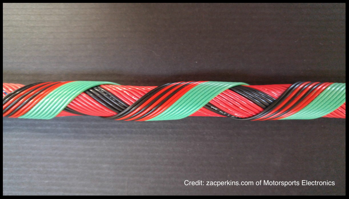
It's also on that page, but for those like myself that have a problem (like frequenting REDDIT CABLE P*RN), make sure you don't miss Zac Perkin's work on his home page here:
ZAC PERKINS WIRING HARNESS P*RN
Aspirational, indeed.
damen
Workdays: 16; Days Since Delivery: 169
Another major piece of the puzzle picked up.
![]()
A CD009 6-spd manual transmission from a 2005 350Z. I found it locally via car-part.com and Nik met me with his truck to pick it up. Good friends are good. We slogged back to the shop 20 miles in 5pm Houston traffic, which takes about an hour. Brutal.
The transmission is pretty light, so it was easy to unload by hand with the two of us. Now it's on the floor of the shop, where I suspect it will live for longer than I'd like to think about.
![]()
The CD009 transmission has a bit of a ridiculous reputation on the internet. It's not hard to find claims that it will hold a 1,000hp drag launch in stock form. I'm dubious of such claims, but it is well accepted that it is an excellent transmission with close gearing (5th is 1:1). Nissan worked to improve the CD00x from its debut as the CD001 all the way through to the CD009. One of the big improvements was going from single-cone synchros in the early versions to triple cones on 2nd and 3rd for the CD009. Shifting is largely improved.
One of the tricky parts of getting a CD009, and not being stuck with the double synchros of the CD008, is actually verifying which box you have. The CD009 came in 05-06 model years on the VQ35DE engine, but not the HR version that debuted in 2006 in the '07 model year G35's. The production run didn't start until sometime in the '05 model year, so just getting an '05 is no guarantee either. Then add the fact that the case markings (you'll see stampings of "CD0 #1" or "CD0 #2") aren't correlated with the transmission version (despite what some may claim on various forums). Needless to say, not being an expert, I was nervous about which version I was actually getting.
Fortunately, this transmission was pulled from a running car at the auto recycler from which I bought it, and they provided me with the VIN (which is also stamped on the transmission case). A quick call to a local Nissan dealer's parts department allowed me to confirm that yes, this car was built with a CD009. I really lucked out with this find. The shifter snicks smartly in and out of gear, so I feel pretty good about it.
A New Project?

Some may remember mention of one of Nik's other cars in the shop with the Datsun- a 2005 Saab 9-2X Aero that was flooded up to the dash in Hurricane Harvey: The Saabmarine.
Nik is recently married and has been looking at paring down his automotive balance sheet. The Saabmarine didn't really have a clear place in his portfolio. He made me an offer I couldn't refuse, so I bought it.
It's in need of some serious remediation, the scope of which still isn't even known this long post-flood. I plan on starting another thread for it, so keep an eye out. I'll post a link here when it's up.
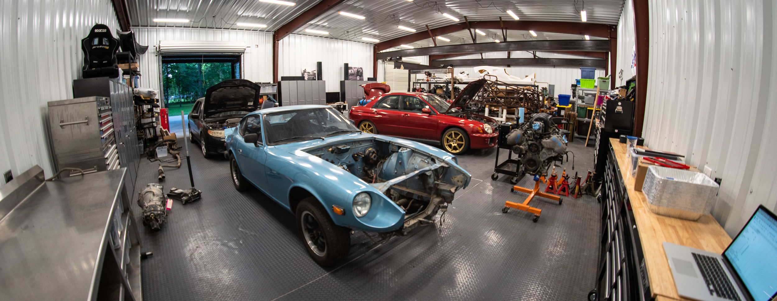
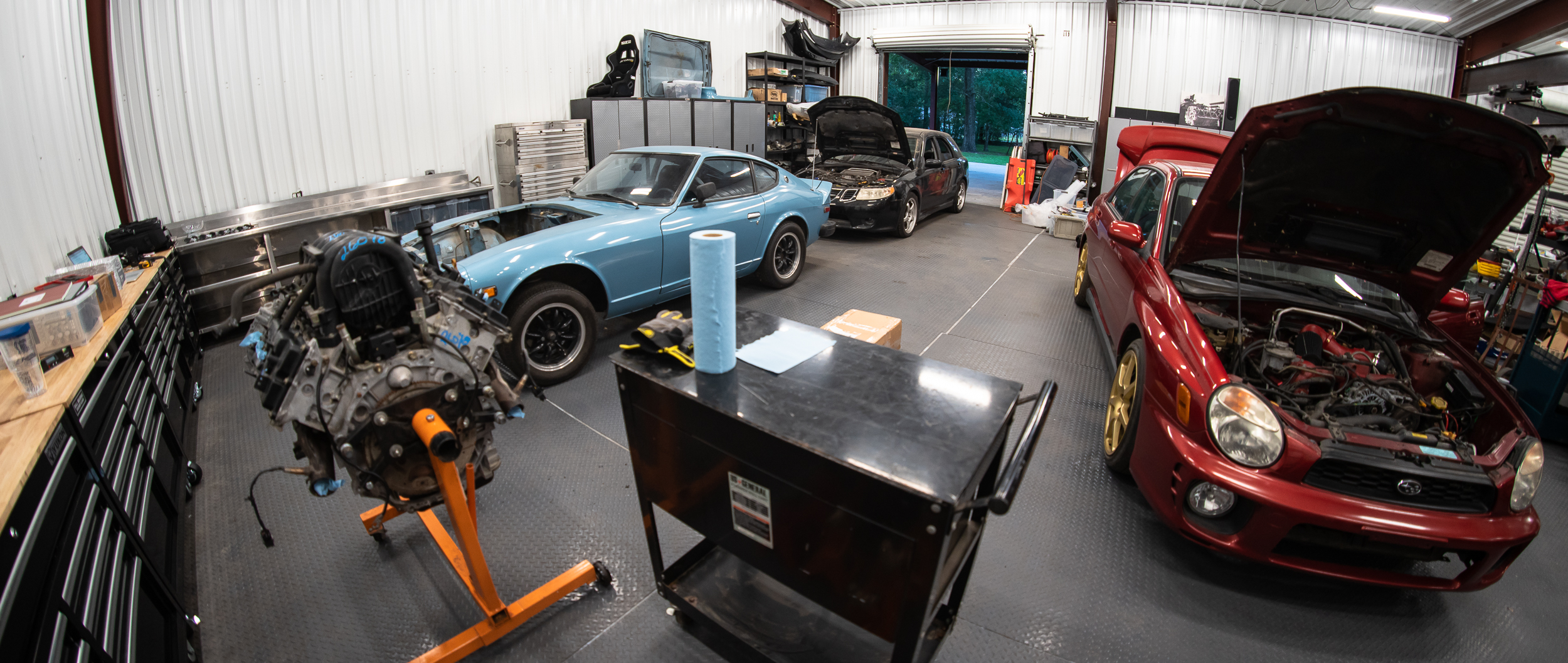
One of the other stablemates (that's lived outside for a couple years), a heavily modified red bugeye WRX purchased as a donor for a Factory Five 818, has bubbled to the top of Nik's list. So after getting the transmission in the shop, we shuffled cars around to get the WRX inside. We pushed the Saab out, drove (with a surprising number of intake/turbo hoses missing) the WRX inside, and pushed the Saab back in behind. It's starting to look a bit commercial in the shop!
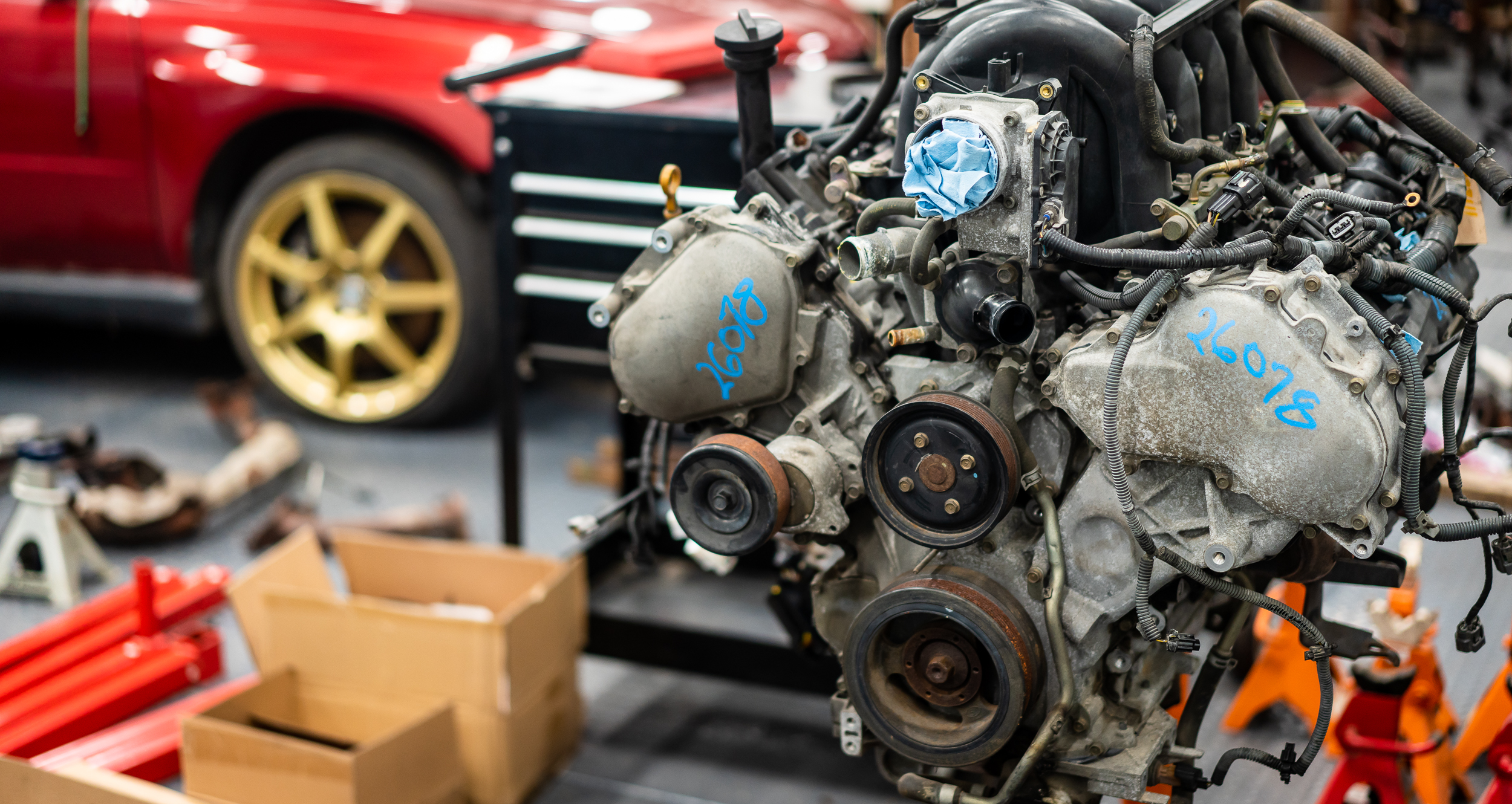
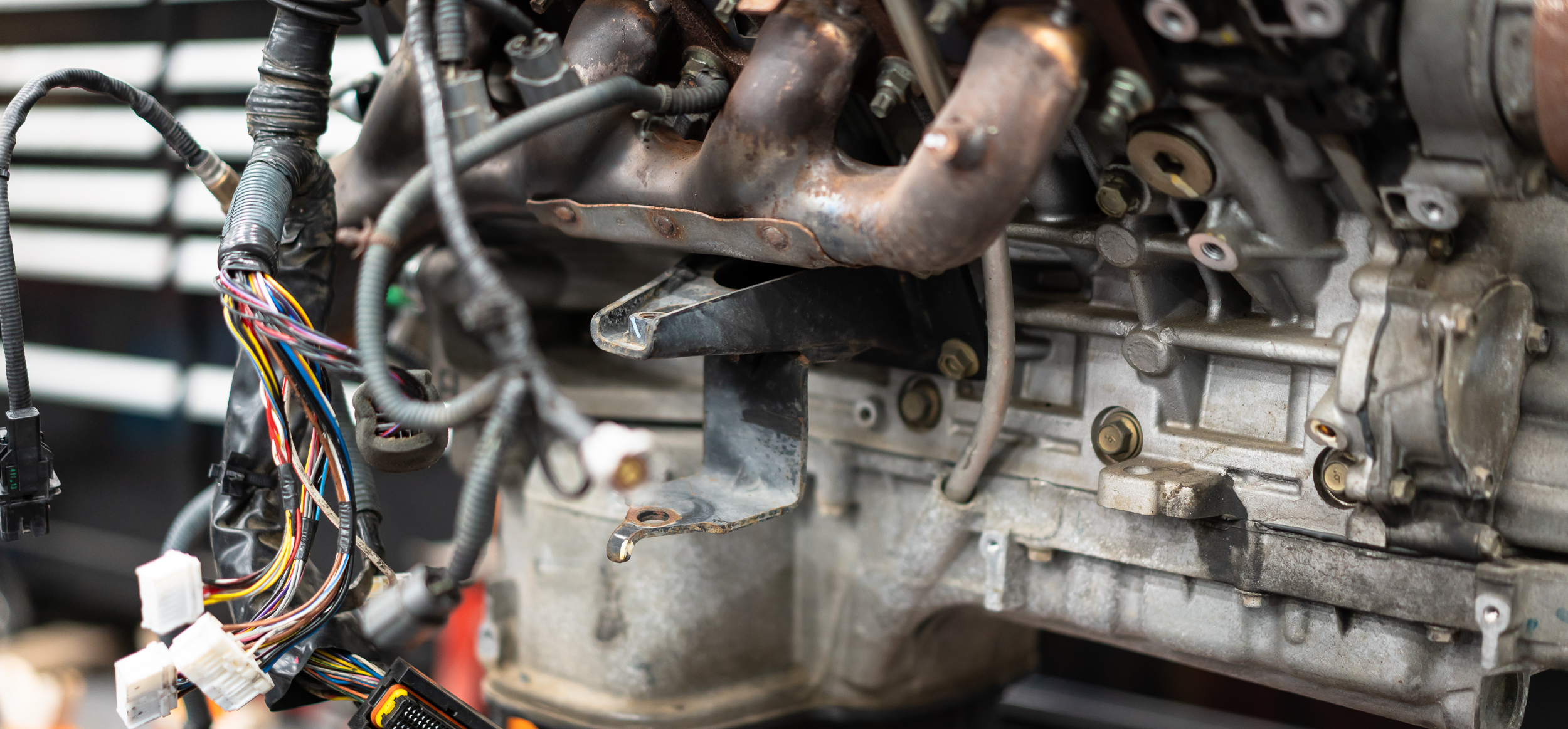
I snagged a junkyard wiring harness that came up on eBay for extra cheap a couple weeks ago, so I unboxed it and draped it over the engine to make sure I had all the connectors I wanted. It was way cheaper to buy a used harness than buy all the connectors separately, which I'm sure you all know anyway. Just confirmed.
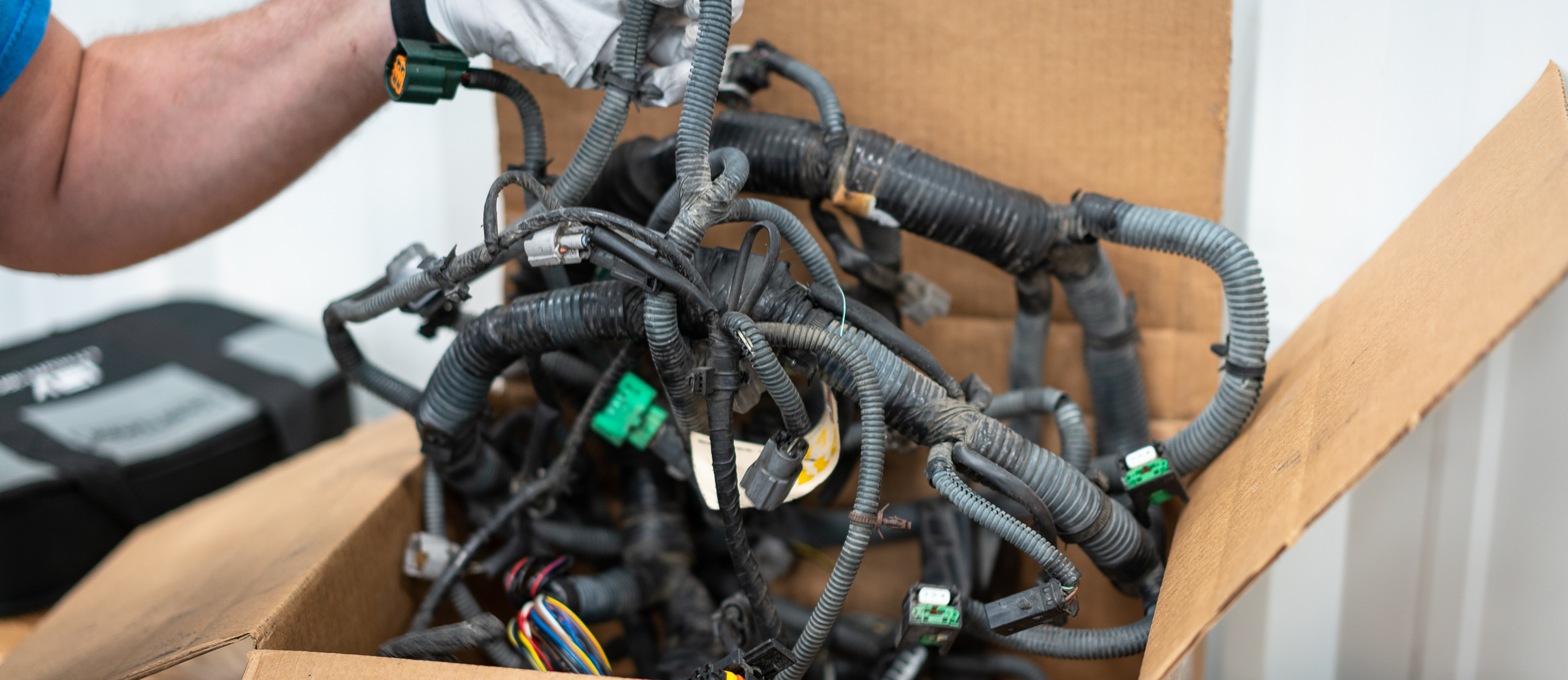
All the connectors are there. My plan right now is to dissect the junkyard harness and harvest wire and connectors to graft onto the standalone harness. I imagine doing this once with the old stuff as practice on the engine test stand, then doing it again with new connectors for the final car harness.
Speaking of which, I also picked up Walmart's finest engine test stand.
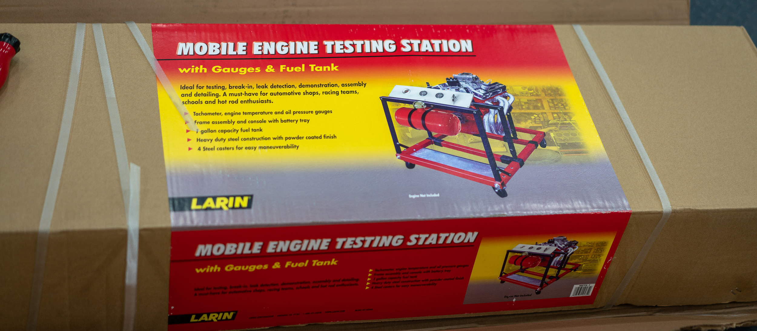
I'm 99% sure this thing is cheaper than I could buy the individual components and metal. Feels pretty odd to get it from Walmart, but we'll find out together how good or bad of a plan this is. I'm sure there will be some custom parts needed to get everything mounted up, but this is a hell of a head start.
While I worked on wiring and unpacking the test stand, Nik re-mounted a giant intercooler on the WRX.
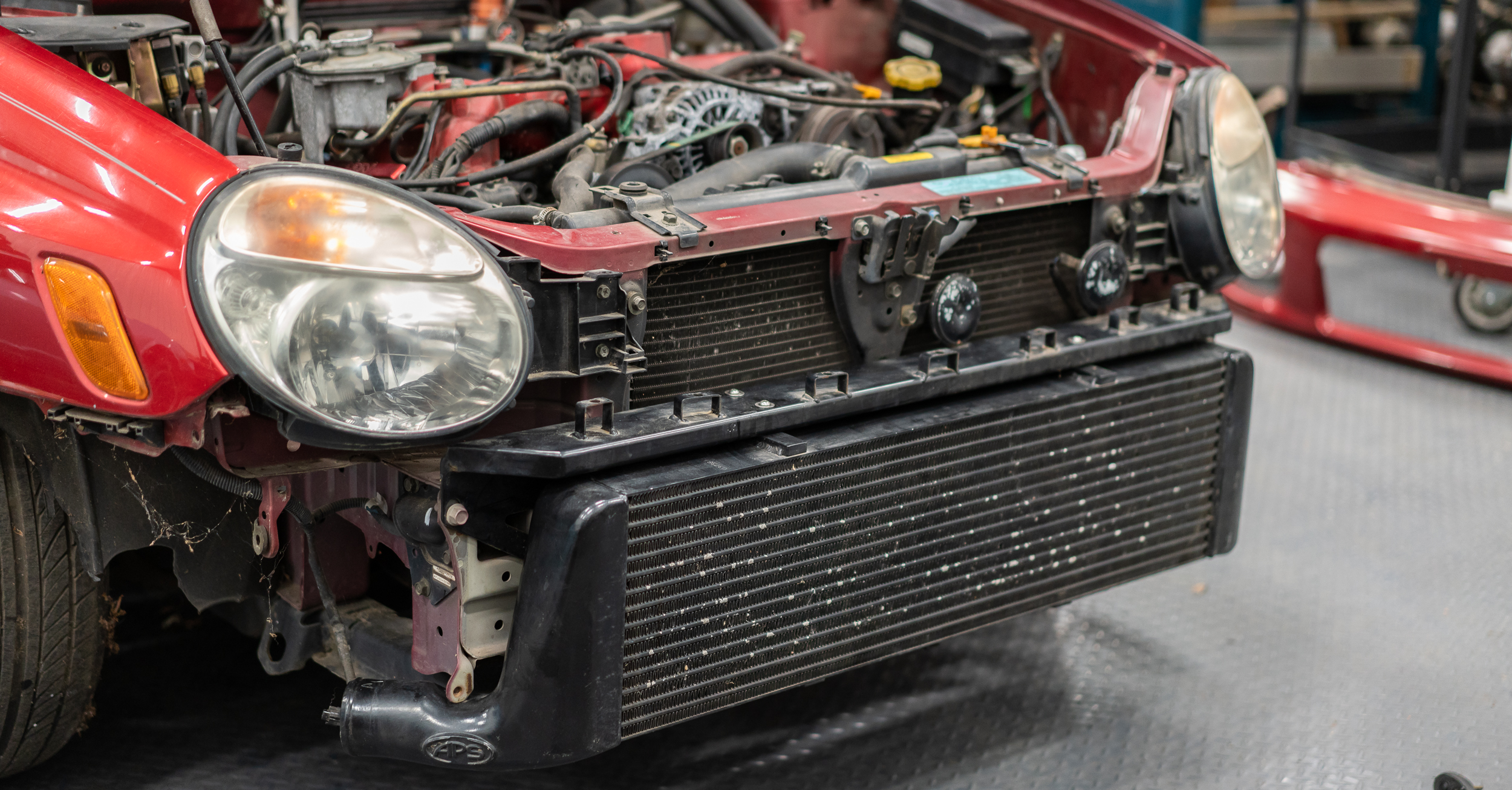
I was pretty amazed, but Nik claims it's nothing compared to what V8 turbo guys run. I don't love turbos that much, so my knowledge is thin in that arena. I'll take his word for it.
With so much stuff happening in the shop, I wasn't super efficient, so I just had time to unpack the test stand. I'll work on it the next time I'm out there.
I was able to measure for a crank trigger wheel, so I have all the information I need to order an ECU and starter harness. I'm balking a bit at the commitment; I was supposed to order today, but I think I'll sleep on it over the weekend. No need to rush a decision on that, I think.
damen
One niggling, yet important, item that was(is) bothering me about the AEM Infinity 708 is the dual built-in wideband controllers. I really like the idea of not having to buy separate controllers for simplicity reasons, but the 708 on-board controllers use Bosch LSU 4.2 sensors. These are old sensors that have been replaced by the LSU 4.9. In fact, the 4.2 is so old, it's hard to find any modern wideband controller that uses them anymore. AEM themselves use the 4.9 in their latest-greatest "X-Series UEGO Wideband Controllers".
This led me to searching for feedback on the differences between the 4.2 and 4.9, and if they mattered.
They do. In fact, I stumbled upon a magnificently (maybe horribly, depending on how much you like electronics design) detailed wideband controller review thread. In fact, it even features a bit of a spat between an AEM engineer and the 14point7 engineer on some seriously nitty gritty design and test details.
MONSTER WIDEBAND CONTROLLER THREAD
Previously, I assumed wideband controllers were a commodity: interchangeable and equal. I learned that this is absolutely not the case; there is a serious difference in the design, implementation, and execution of these things which leads to wildly varying accuracy, response time, and longevity. Most of the controllers on the market were measured having more than 0.5 Gas AFR errors, usually to the rich side (meaning the engine was running 0.5AFR LEANER than the controller showed).
Yikes.
The AEM X-Series was released with great fanfare and a pretty unique design; test results show that it is probably the fastest responding controller on the market with good accuracy. AEM released the results of third party testing (which they paid for) showing their controller to be the fastest by some margin:

The 14Point7 Spartan2 carries a very nice reputation for quality (backed up by a 2-yr warranty, vs 6 months for many other products; AEM = 12mo) and accuracy. 14point7 guesses they'd be in the low 40ms response time; they optimized their design for accuracy and reliability and let the response time fall where it may.
Given all of this, I've decided that it's more important to use accurate wideband controllers rather than keep everything tidy. One side benefit to this is that it will allow me to step down from the Infinity 708 controller to the 508, which saves me $1,000. The other features I lose with this move (dual drive-by-wire, dual h-bridge, 4-wheel speed traction control, etc) are not important to me. The only thing I see that may be a bummer is that there are almost double the amount of digital and analog inputs available on the 708. I don't think it's worth the price difference. I may regret that in the future.
As far as wideband controllers go, the AEM X-series controllers are $235 vs the 14point7 Spartan2's $125. The added benefits of the AEM are speed and the ability to send AFR readings over AEM's CAN implementation (AEMnet), which would free up 2 analog inputs that may become scarce. Might those extra inputs be worth $110 each at some point? Given my affinity for data collection, I'm leaning towards yes, but who really knows.
What do you guys think? I've had some great input from here before-
damen
Not much has been happening on the 280 since I've acquired the Saabmarine racecar.
I have been gathering parts, though.
I pulled the trigger on an AEM Infinity 708 standalone ECU, along with a starter wiring harness. I want to at least try the dual onboard wideband controllers, and it has double the amount of I/O as the 508.


One of the big changes that needs to happen to get the motor running in stock form is the crank trigger setup. The stock implementation is a giant goofy pie plate notched wheel that's bolted to the flex plate (this motor only ever came paired with an automatic) and a sensor that bolts to the transmission bellhousing. Which I don't have.
So I'm going to run a 36-1 trigger wheel with an inductive VR sensor at the crank. DIYautotune has a nice 8 1/4" wheel for cheap and I found a VR sensor on mouser that looked good on paper.
What I didn't realize is that the sensor is sized for cruise ships. The thing is absolutely massive; the nut on the threaded body needs a 27mm wrench. Whoops.
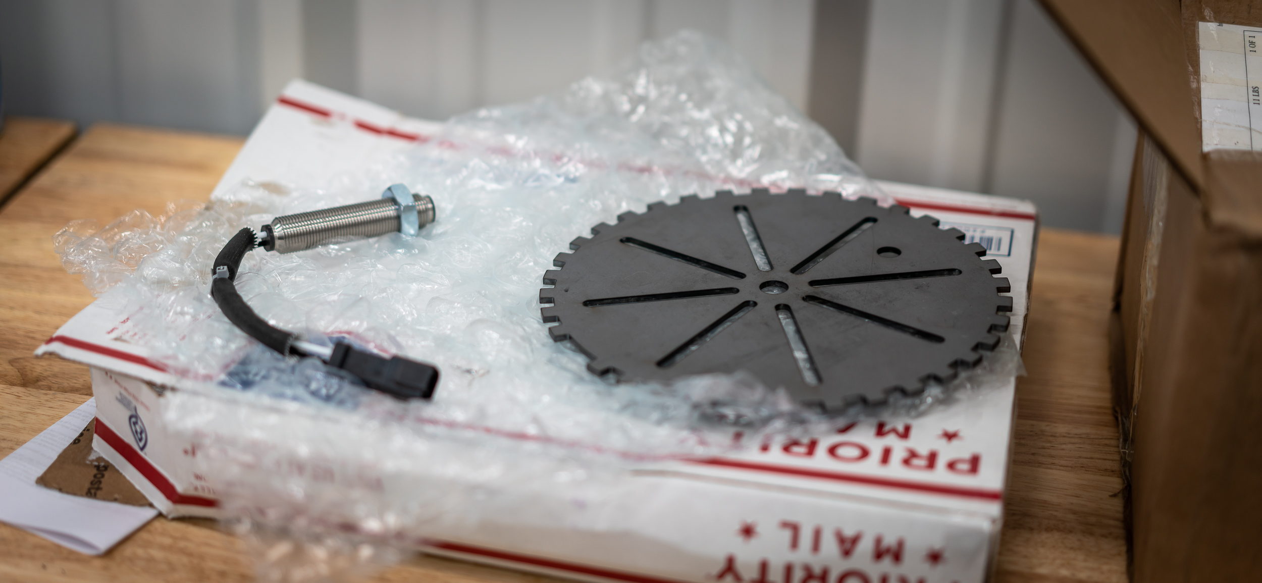
It wasn't terribly expensive, so I'll probably just keep it to practice with for now. In fact, I set up a small test to see if I could see a waveform out of it.

Unfortunately, I had no idea what I was doing, so I stopped before I accidentally sawed my sensor in half with the trigger wheel.
So I bolted it up to the crank pulley, which for some reason has 6 M6 threaded holes in the front of it.
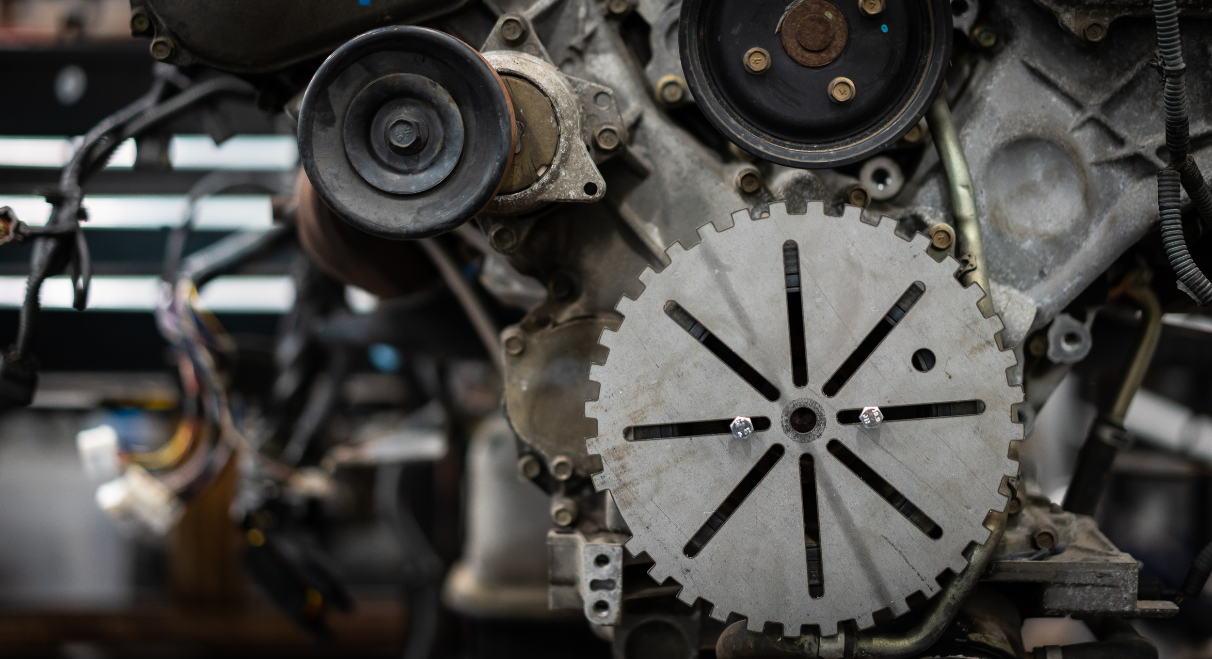
Good lord that's ugly. Not to mention it weighs like 1.3 lbs. I'm not sure this is the final solution (in fact I'm pretty sure there's no way either of these pieces will be on the final build), but they should suffice to give me some practice with setup and programming on the new ECU.
At least that's what I'm telling myself. I sat in the car for a few minutes thinking about this whole project. I became overwhelmed so I stopped.
Small bites of the elephant and all that, I suppose.
damen

Trigger wheel and trigger sensor mounting can be a challenge. The wheel needs to be well centered, and not fixed to an outer part of a two-part pulley with a rubber damper. Your M6 holes are probably in the center for a puller attachment so they should work fine.
The other thing is getting the sensor to sit steady - the mount can't flex at all, then the sensor will move around and give bad triggers.
If it is possible to have the wheel sitting behind the pulley, closer to the engine block, that usually means mounting the sensor will be easier (and it will look neater. Maybe someone can machine out the center of the wheel you have?
Gustaf
In reply to therealpinto :
Good morning, Gustaf-
Thank you for the good tips, I will incorporate them into my efforts.
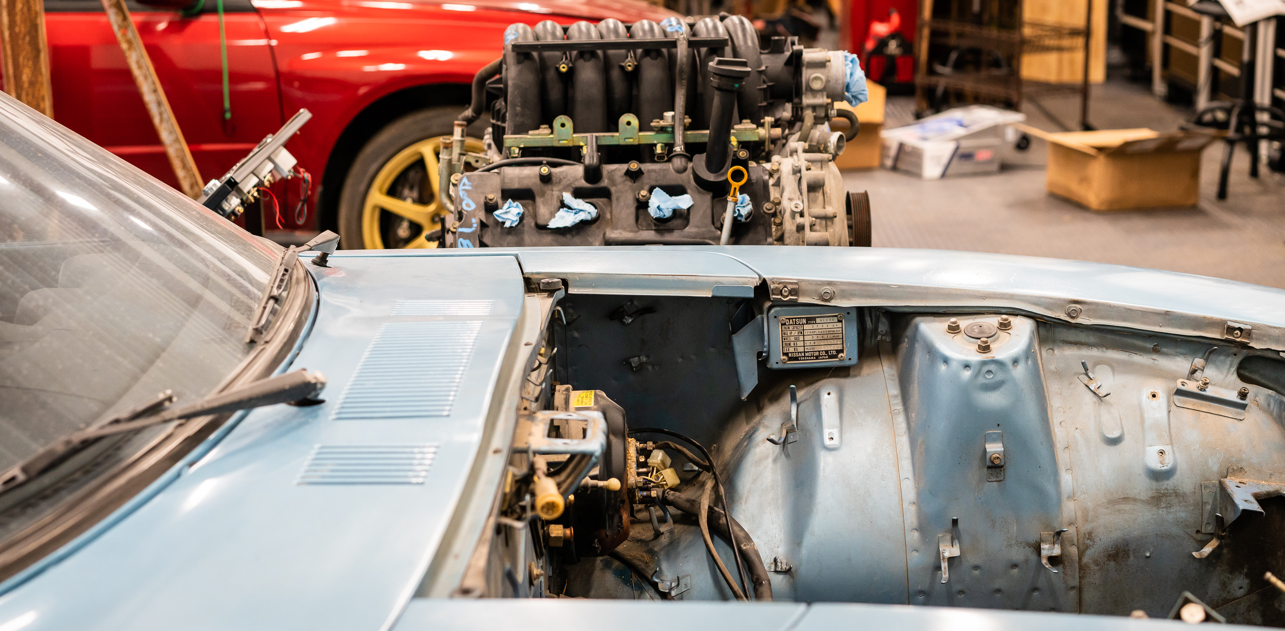
I agree that it would be better to have the trigger wheel behind the pulley, however, the space is not good for that at the moment:

The first problem is the coolant lines to the "oil cooler" which is built into the filter mount. The trigger wheel will interfere with these. This will eventually not be a problem as I will be installing a proper external cooler, but it is in the way for the moment.
The more concerning interference(s) are cast protrusions in the block. It's not clear at this point whether those can be circumvented somehow.
I will make sure to start with a very sturdy sensor mount.
I have access to one of the best machinists on the planet, so I imagine (hope for?) a much tidier solution at the end. This first step is really just to learn the ECU by getting the motor running on a stand, if possible.
Cheers!
damen
Yes, that looks tight!
Frount mount may be a necessity but perhaps with a "hub" that holds the trigger wheel to the center of the pulley. Looks like there are some nice holes to work with there.
Gustaf
I've started a new thing where I get really excited about the idea of the 280 being complete, then carry that enthusiasm into starting a work night on the car, then slowly tumble down the hill of overwhelminess as I work and land in the puddle of despair by the end of the night.
How am I ever going to get this done? I'm now over 6 months in and I wouldn't disagree with anyone that said I haven't even really started yet. I suppose it is best to not think about the project as a whole; I can't handle it. Perhaps the only way forward is to not look farther than the task at hand? But then I'm not sure that's sound project management theory.
Gantt chart?
Blindfold?
Advice/empathy/ridicule welcome.
Existential crisis aside, I bought a "Mobile Engine Testing Station" from Walmart. I would like to try to get the stock engine running on the AEM Infinity ECU with a needs-to-be-made wiring harness, using the 36-1 trigger wheel and VR sensor, on an alpha-N / VE map. And I've never done any of that. But it'll be fine, right?
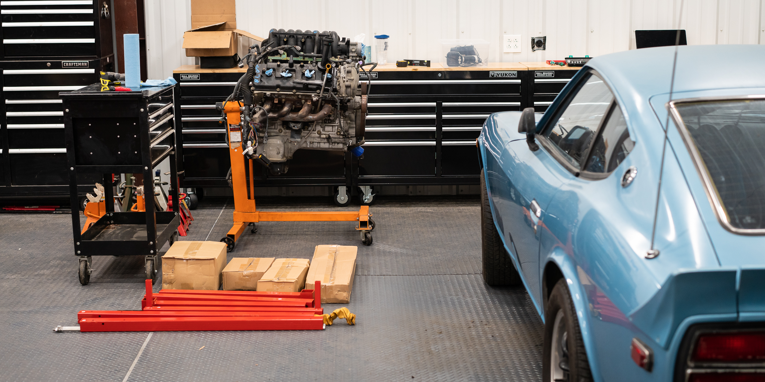
Anyhow, the testing station/engine stand came in a lot of pieces with very little documentation. Like IKEA, except with no directions. Just a photo of the finished product.
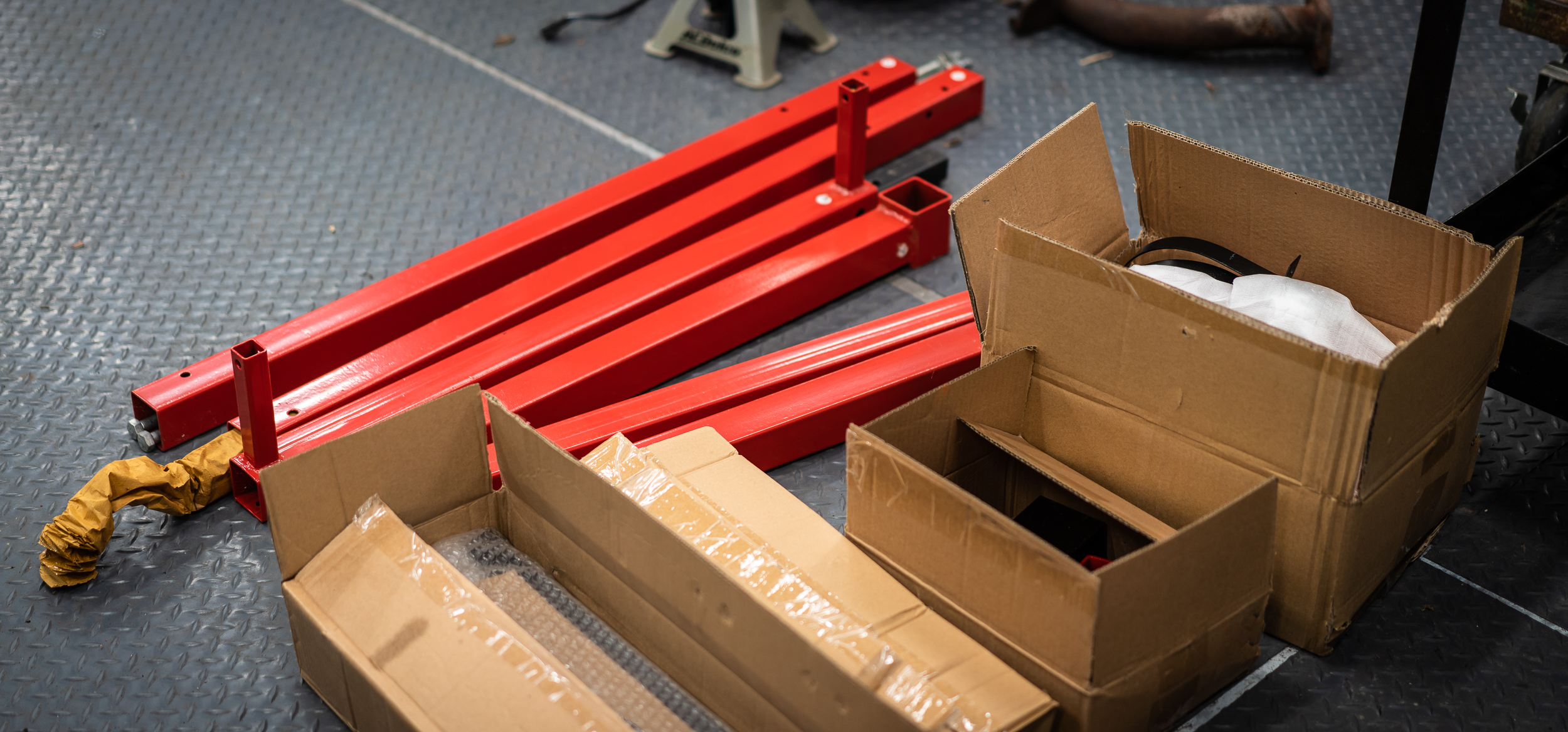
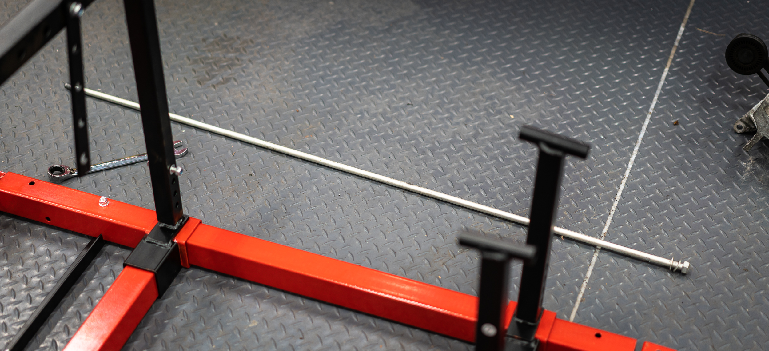
I got it about halfway together, planning to put the casters on last, when I realized that the casters have bolts that need access to the inside of the tubes to install. So I took it all the way back apart, which at least gave me the opportunity to take a photo of the 4 foot long bolt that holds the bottom together.
So I got the casters on, then restarted assembly.
I made it to 95% complete. All that was left was to fasten the diagonal supports for the fuel tank/instrument panel. The supports wouldn't reach by about 5mm. I was very close to writing it off to "poor quality control" or something like that when I realized that the very bottom legs were upside down and flipped side to side. The only difference is the one support hole being a bit higher when properly oriented. Here's how it looked 95% complete.

It would have to come fully apart again. I was not a happy camper. It was hot.

That's a 107 heat index. I briefly considered drilling the holes in the place I needed, but I figured the extra labor was appropriate punishment for screwing it up twice.
So I took it apart, flipped the lower legs, then reassembled again for the third and final time. This 15 minute job took 2 hours.

It would have been nice to try and put the engine on this shiny new stand, but the mount arms on the engine need a vertical bolt orientation while the test stand uses a horizontal bolt orientation. I'll have to make some sort of adapter. After measuring, I think I can come up with something using 4" x 2" 3/16" wall rectangular tubing. We'll find out together.
I had some extra time left before having to leave, so I started on the wiring harness mock-up bit.
I read somewhere about someone using solid-core single-conductor wire to mock up wiring runs, so I thought I'd give it a try. It's pretty cheap stuff. $37 for 500 ft at Home Depot.

After I marked all the connectors on the stock harness (I'm going to harvest the connectors off of it for the first test harness), I started running wire to a common spot at the back of the engine, and labeling. I'll add probably 3-4 feet extra to the harness, but no need to waste the mock-up wire.

I can then take the white wire and lay everything out on a table to make a harness. I ordered a starter mini-harness from AEM for the first pass at this. I'm hoping to make a nice harness for the final product with Spec55 wire, Raychem shrink tubing, etc. I'll use this first go round to test both layouts and construction methods.
I only got one side finished, then put it all in a box to take home and work on if I have time between shop nights. Most likely I'll just drive this box of wires around in my trunk for a couple months before using shop night to work on it anyway. It's pretty busy at home with a 2.5 and 0.75 year old.

Until next time.
damen

Good idea on the solid core wire, I'll put that in my back pocket for later. Sounds like assembling an engine run stand is similar to putting together a cheap BBQ.
Keep plugging away, eventually you'll be done and wondering what to do next.
Adam

Have a pucture of what you want to OWN at the end of the project. Then, focus in on one area at a time. Engine bay for example. That means engine running. Then tided up.then mounts. Then....
One step at a time, one inch at a time towards what you want to OWN
In reply to Dusterbd13 and adam525i:
Good points my dudes. Thanks for the tips-

Your good humor is an excellent antidote to feeling overwhelmed. Despite it all, you are making progress. Nice build, and a good read.

I just focus on what I feel needs to get done now. It is all progress. My project is at where I would have liked it to be 2 months ago. Just keep trying to get something done as often as the rest of you life allows, eventually you will have a finished project.
In reply to Dirtydog :
Very kind of you- thanks for that.
In reply to zordak :
Good call. Bites of the elephant and all that, I suppose.
It seems I'm still working at not looking at the elephant whilst I chomp.

In reply to badwaytolive :
DO NOT look at the elephant. This gets harder to do as you get close to the end and want to have it done.
Pete
I swear I had the world's most magical glorious internet post in all of history about 90% done and then fumble clicked my way off the page and lost it all. A serious Pulitzer contender, lost to the ghostly annals of digital ether. I know many of you feel my pain.
Anyhow, now you get the cliff notes, which is probably all most people want, at the most, anyway.
Because the engine test stand I bought is meant for domestic V8's, it won't bolt up to the incomplete Nissan mounts on my motor, so some sort of mount adapter is needed.
I searched around town (Houston is a good town to find raw materials) for the 4" x 2" 3/16" wall rectangular steel tubing I spec'd for my in-no-way-qualified design. I could find plenty of places to sell me 20 feet of it for ~$140, but I needed < 1 ft. for this project. I don't want 20 feet.
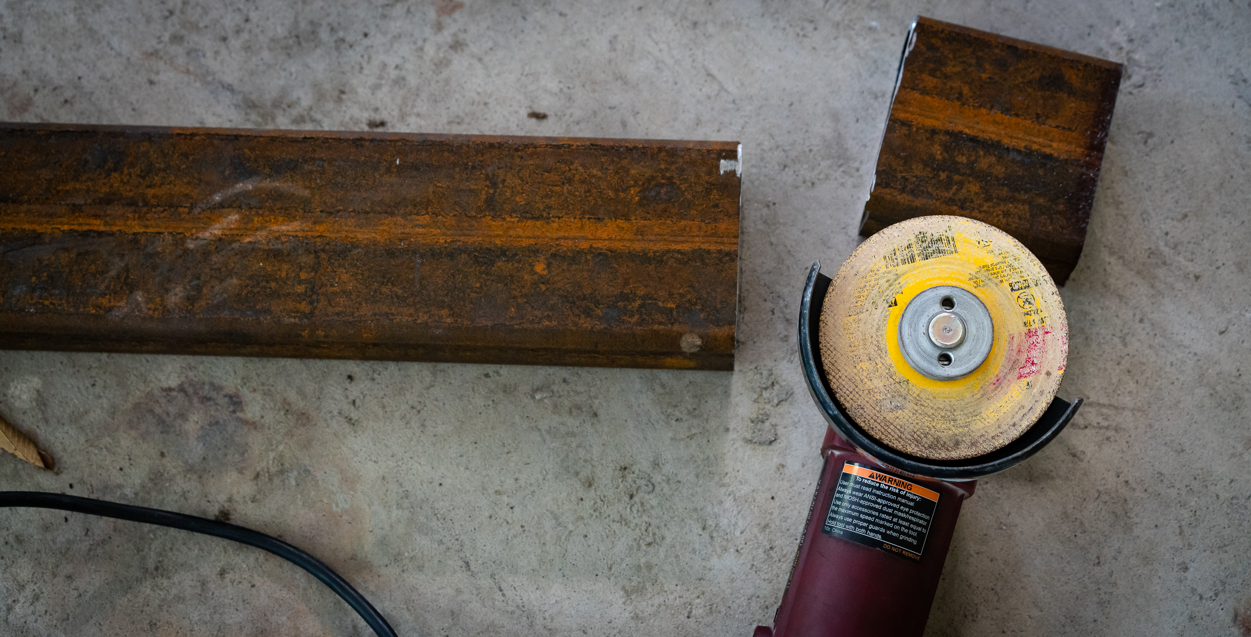
My cold calling scored when I talked to TEXAS IRON AND METAL. They had "less-than-prime" surplus material in the size I was looking for and they'd slice me off any size I wanted. I figured it might be a handy size to have as extra around the shop, so I got 4 ft. for $27.

This 4 ft. piece is like 30 lbs, so it's pretty beefy. I originally wanted 1/4" wall, but that wouldn't fit where I needed, so I hoped 3/16" would be enough. After slinging this piece around, I'm glad I didn't get 1/4". Plenty heavy.
They weren't kidding about "surface rust" on their surplus material.

Living outside in Houston is cruel and unusual punishment for the ferrous among us.
I feel like achieved a milestone for this project: First use of His Royal Highness, the Grinder of Angles, Leader of Men, First and Last of His Name.
I actually would have preferred to use the horizontal bandsaw, but that thing is buried deep in the bowels of the yet-unattended-to fab space in the shop.
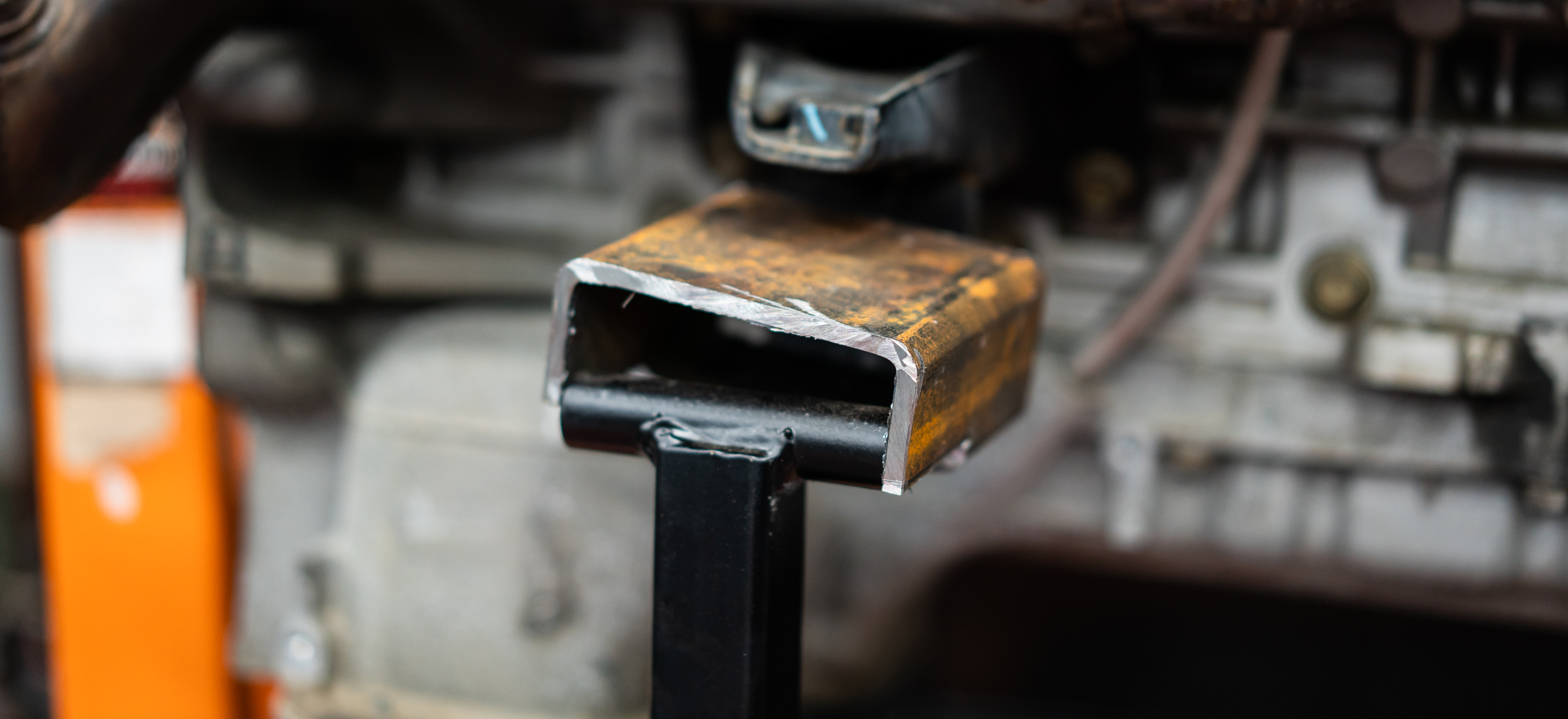
Next I chopped out half of the bottom to fit over the stand side mount. Here's how that all looked, set in place:
The next step was to drill (4) 1/2" holes. I'd asked Nik earlier in the day if there was a drill press in the shop.
"Not really."
??
Upon arrival, I learned that he had a very old drill press that he bought off craigslist 5 years ago. It had started up once when he bought it back then, but hadn't been tested or anything since. I really didn't want to hand drill (8) 1/2" holes in 3/16" steel, so I decided to spend a few minutes to clean and lube it up and try to get it to turn.
So I cleaned and lubed and plugged it in and hit the start button.
Success!
It even has an olde tyme speed adjustment lever that somehow changes the diameters of the drive and load pullies. Neat. Anyhow, with that working, I made the first 4 holes in no time.

Test fit #2 is good.
So I flapper-wheeled most of the crust off and painted it. I'd post the painted final photo, but I used some magic rust-inhibiting black rattle can stuff that absorbs some crazy amount of light, so that pic just looked like a hole in a workbench. This is post-flapper, pre-paint:

Then painted and installed with some "spacers":
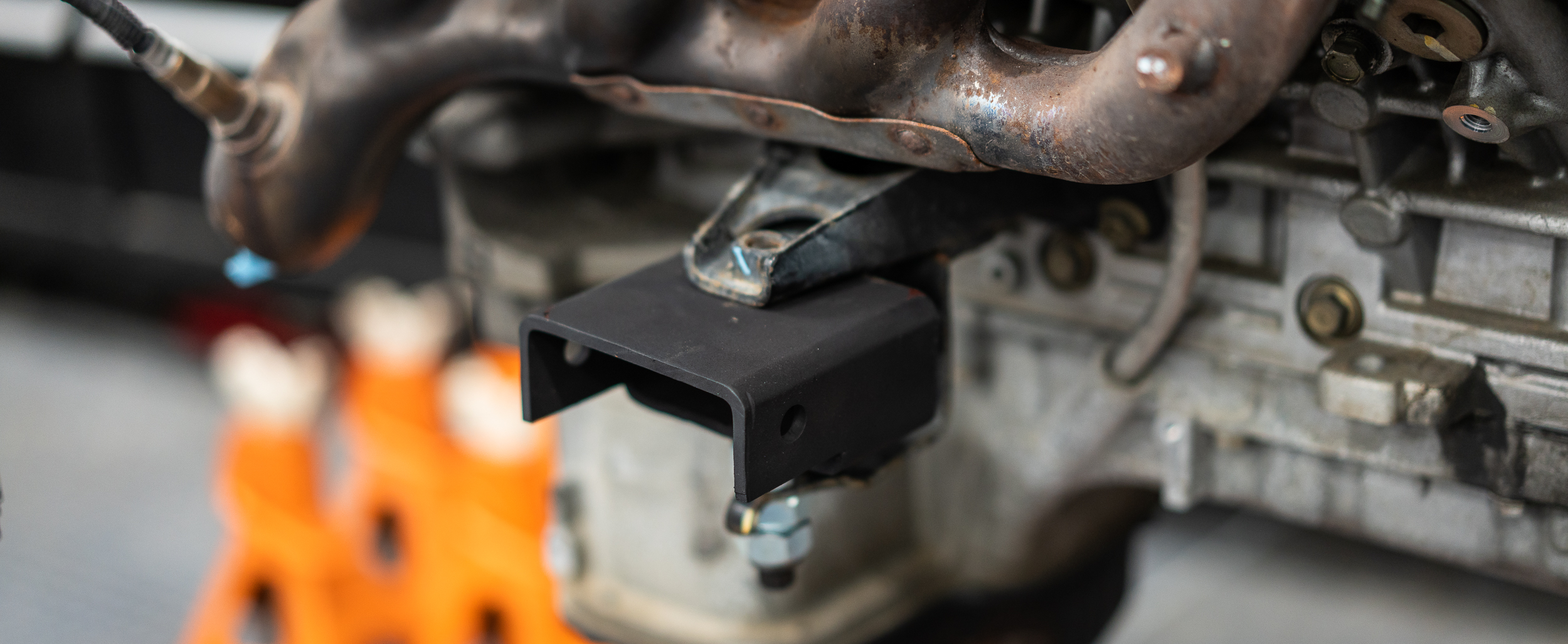
I'm an inordinately slow worker (as I think we've well-established at this point), so it took a couple hours to get to this point.
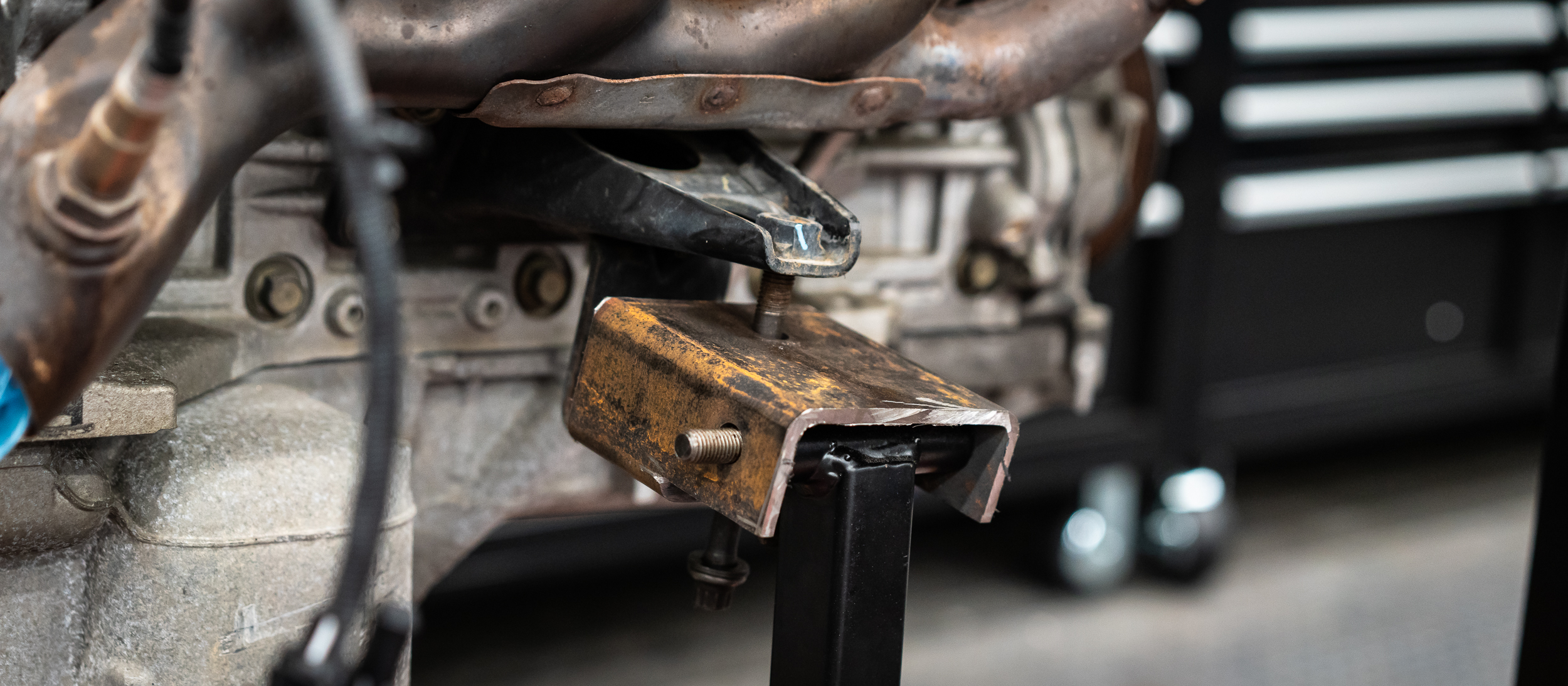
And then I did a second one. In youtube time, that takes < 1 second. It took me like 30 minutes, which I was actually pretty happy with. So I bolted the second one up as well, which meant it was time for the move!
There weren't any obvious spots or bolt holes to lift the engine. The internet shows a lot of people pulling the intake manifold and bolting to something down in there. The junkyard used a seat belt around 1 header and a metal bracket on the front.
I found the bracket, which I'd taken off, and put it back on. Nik found a 6400 lb. strap and some carabiners. So we did the move, junkyard-style.
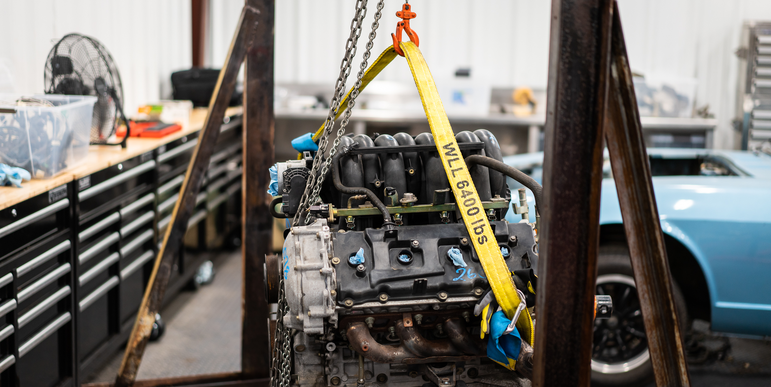
Lift, unbolt the Harbor Freight stand, wheel away, wheel in the new test stand. It worked a treat so I set about finding all the nuts and bolts and washers and bolted everything together. It was a bit fiddly because the stand is so adjustable.
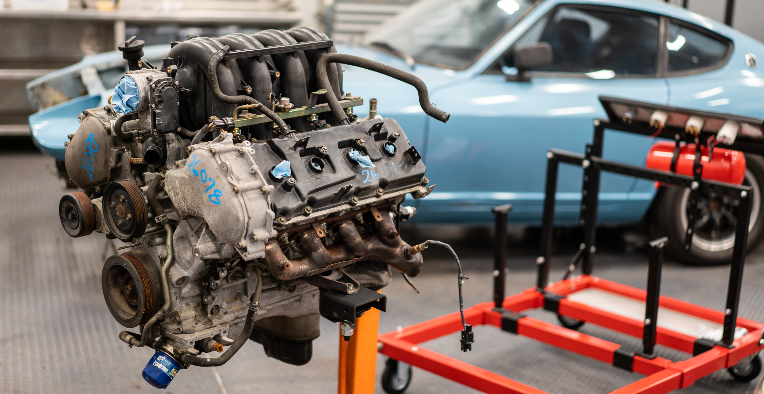
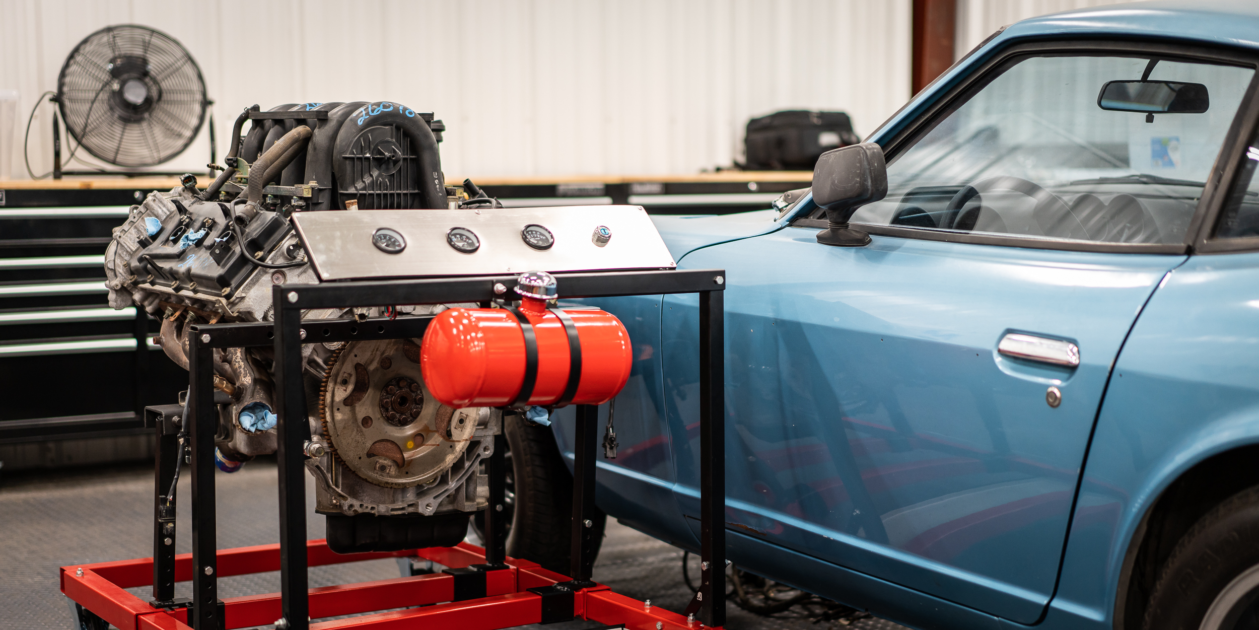
Happily, I was able to find settings on the stand that put the engine in what I consider to be a pretty happy place. Low and centered.
In fact, it's almost even level:

Make the noiiii...... ah, no. Not level by 0.90 deg. Ah well, I'll take it.

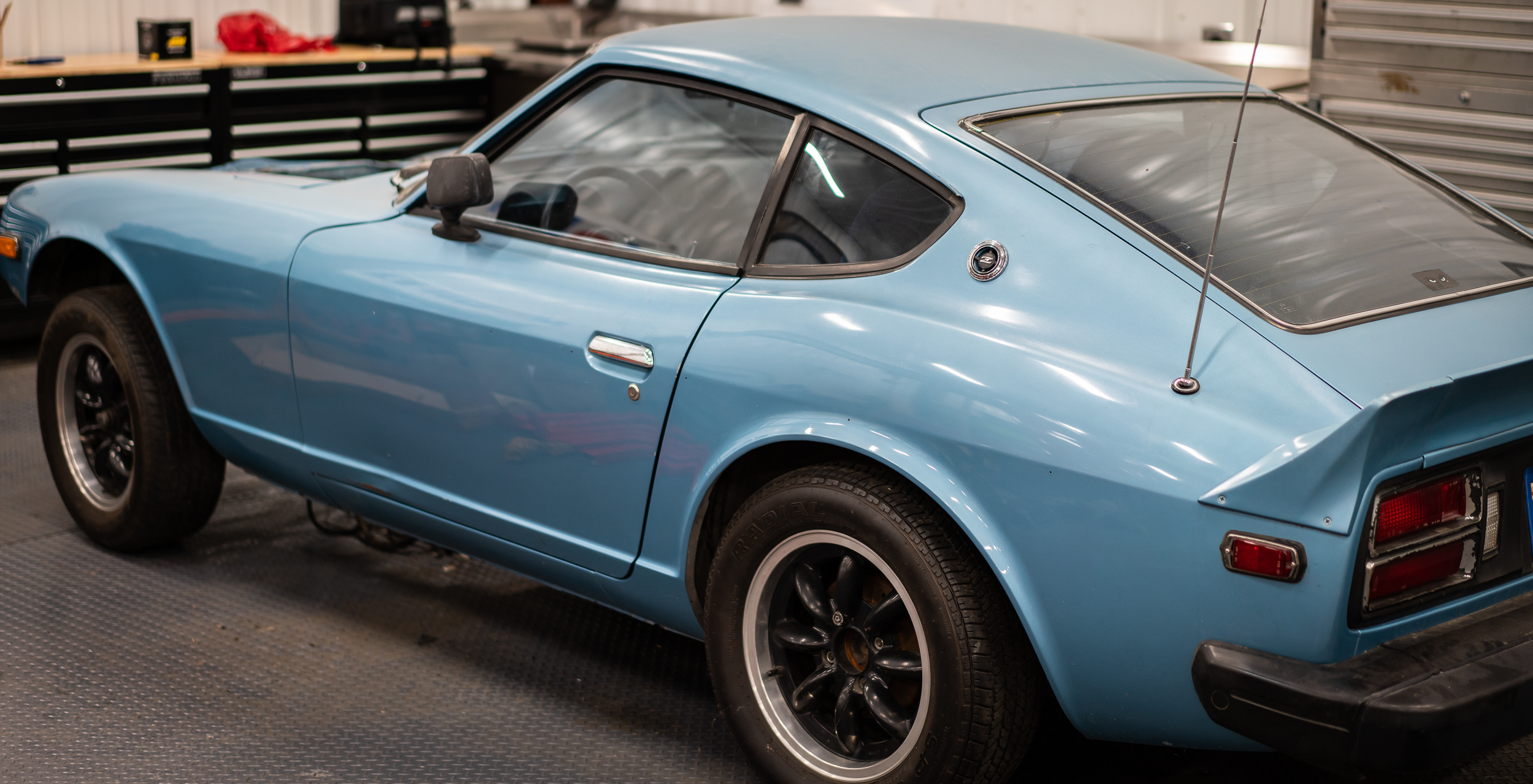
Satisfied with the night's work, and despite the fact that it was midnight, I couldn't resist pushing the motor next to the car in the forward/back position I've been brainstorming. That's the position in the above picture, and in this one:
Not a good omen for the firewall.
I took a quick measurement of the transmission on the ground (~32") and added that to the back of the engine to see where a shifter would be with the engine located here. I didn't take a picture, but it wasn't quite as bad as I thought it might be. Maybe 6-8" behind the stock location?
Anyhow, for some reason this felt like a very satisfying accomplishment for the night.
Next is continuing with the wiring harness.
damen
Nice work. Now that you have practiced with The Grinder of All Things Metal, on 3/16", a mere firewall should pose no problem.... "What the firewall giveth, the remover taketh away". Measurement matters. Keep up the good work.

Wow, that's a nice clean Z. I wouldn't cut up the firewall on something as nice as that, but hey it's your car. Seems like matching the shifter on the trans to the stock location would make the most sense....

Your pictures are absolutely beautiful!
Loving the swap too.
In reply to Dirtydog :
Ha, good stuff. Thanks!
In reply to mblommel :
I read somewhere that firewalls are merely a suggestion :) I confess to not taking all this car stuff too seriously, I'm just in it for the fun, I'm afraid.
I was mostly just checking to see where the shifter landed "naturally". It was always the plan to have to do some sort of re-location via linkages, I just wasn't sure if it was going to be a 6" relocation, or 26". I've penciled in an engine position that puts the front pulley just behind the "front axle".
In reply to Run_Away :
That's the nicest thing anyone's ever said to me! I try overly hard on the photos, so thanks for that.
Pray for this swap; having zero experience or talent in any of these particular arts, I need all the divine intervention I can get.
damen

badwaytolive said:I swear I had the world's most magical glorious internet post in all of history about 90% done and then fumble clicked my way off the page and lost it all. A serious Pulitzer contender, lost to the ghostly annals of digital ether. I know many of you feel my pain.
...
It even has an olde tyme speed adjustment lever that somehow changes the diameters of the drive and load pullies. Neat. Anyhow, with that working, I made the first 4 holes in no time.
I've lost post drafts here on the GRM forums as well. If you accidentally click the back button on your browser and then forward again, it's gone. Doesn't get cached anywhere apparently. GRM uses some fancypants forum architecture that looks nice but doesn't function as well as the standard vbulletin & other platforms. What I end up doing is typing everything out first in a Word doc and then copying it to the forum, so as not to lose everything accidentally.
That drill press probably has a CVT. I have a 1952 Craftsman (King-Seely) inherited from my grandpops that's set up this way. Quite nice to have.

Holy cats man, you and I have SO MUCH IN COMMON with our builds!
This is my first time visiting your thread (sorry, it won't happen again!), so I'll summarize some of the things I wanted to respond to in the last page or two.
First, wide-band O2 sensors. Just use the native controller in your ECU. This is a case of over-thinking things for sure. Faster sensors are neat, and also not needed unless you're planning to run this engine at the ragged edge of power. Which you're not.
Second, wiring harness: wiring everything is pretty easy, but a E36 M3 ton of work. Like days and days of work. I did some with the engine out of the car, and some with it in. I had to do both for sure. If you have a factory harness that you can screw to a big board, lots of people do it that way. I was inventing the wheel (EFI on an engine that wasn't EFI) on my build, so I started from scratch.
Third, trigger placement. I'm using the same giant reluctor, and it works great with a VR sensor. It won't work for a Hall sensor because the tooth placement is too close together. There are many smaller VRs out there - the one you've got is lousy in form factor. Look for most any european car crank sensor. Anything running Bosch L-Jet. It's a gross generalization, but most euro cars from the 90s will have a nice compact sensor with three wires- the third is a shield. As therealpinto said, mounts need to be strong. Advice I've received: build your sensor mount as though you were going to lift the engine with it. Vibration is bad, so don't build a diving board. Runout on the trigger wheel needs to be low. Less than .015"TIR if I recall. I made mine way more accurate than that, and you should try to.
The test stand is a nice way to go. I considered going down that path myself, but I had confidence I could make it work in the car. Judging by the level of preparation I see you putting into this build, I think you'd do fine going straight to the engine bay if you chose.
I love the detailed documentation - I like to document my own stuff the same way, mostly as a reference for myself. Keep up the great work.
You'll need to log in to post.


