


Neat build , are you changing the rear end or do you think it will take the extra HP ?

Neat build , are you changing the rear end or do you think it will take the extra HP ?

In reply to Mezzanine :
Great post, thanks for stopping in!
I have been really enjoying you Fiat thread- great work! You are quite a bit ahead of me, which is quite lucky for me. Always easier to follow than lead :)
I did in fact order the ECU with dual onboard controllers. I suspect you are right regarding the overthinking, so I will give it a shot. However, I couldn't resist the opportunity for a test, and I found a satisfying price on the AEM X-Series Wideband Controller and Gauge (with AEMnet and 0-5V output), so I will be able to stick that in and compare the new vs. old technology. Plus, I want a wideband for the Saabmarine Racecar, so it's pretty much a win-win-win situation.
As far as running at the ragged edge of power, I feel like I'm going to be sort of close to that, so I'm curious what your definition of ragged edge for this motor is? My plan is around 600hp at 8,000 to 9,000rpm, naturally aspirated.
I do have a factory harness, but it is a giant beast with far more connections than I will be using, so I'm just going to start from scratch. To be honest, this is just a practice harness to use on the test stand. I will make another one once the motor is in the car with all the fancy trimmings.
Thanks for the advice on the VR vs Hall Sensor! My Roush-Yates EFI amigo steered me very hard away from Hall Effect, which I was leaning towards originally. Imagine that - he appears to be right on. Great data for me as well with you using the 36-1 behemoth! I will use your parameters to find a more appropriate VR sensor- thanks for that, as well as the mount construction tips; I will certainly follow them.
I'm looking forward to wiring up and working on the engine on the test stand. Access has never been and will never again be so good, so I'm enjoying it while it lasts...
I hope you continue to participate in the thread - thanks again!
damen
californiamilleghia said:Neat build , are you changing the rear end or do you think it will take the extra HP ?
Thank you!
The internet has led me to believe that this car came with the semi-desirable long-nose R200 rear diff. It is an open diff, but there exists many options to install an LSD, which I will certainly do.
To be perfectly honest, I haven't even confirmed which rear end I have yet, let alone develop a plan for the back half of the car. Mostly, my wallet is too afraid of the answers.
One thing that works in my favor is the engine I'm building will not make much torque down low. In fact, it probably won't even make 400 lb-ft, so maybe I can get away with less beefy parts than I first imagined. I do really dislike the u-joint half-shafts with stub-axles setup, so I will definitely change that at some point.
Depending how I feel (sometime very far in the future), I might just connect the stock setup to see what happens and go from there. At the same time, I want to run 275/40-17's, so I may have to start from scratch. Who knows.
Fortunately or unfortunately, I don't think this will be for quite some time. I'm terribly slow.
damen

In reply to badwaytolive :
Damen...friend. of mine is Richard Holden. He is out of Memphis and has been campaigning a Z car with transplanted 370Z engine on the national level in autocross. (XP) He would be a great resource on some of your suspension setup, rear-end, Etc. I know he's on Facebook so you may try to tag him there. I'll try to get his contact info for you but I'm sure he would be more than happy to offer advice, technical guidance, etcetera. Jim Pierce

First off I love this build. Good find and detective work on that CD009. I picked up one out of a 370z just to be safe after I almost got swindled on two separate occasions.
If you don't have the driveshaft from the Z are looking for a slip yoke for that output shaft I did quite a lot of digging to find one for a reasonable price. I wasn't willing to shell out $170 to Collins adapters for something I thought was worth about half that. I found this after a few days of cross-googling part numbers. It fits on the splines and the output shaft seal, it does make some contact with the thin metal cup around the output shaft when it's fully compressed. I think this is due to the fact that this is a 1330 u joint rather than the smaller 1310.
Ovid_and_Flem said:In reply to badwaytolive :
Damen...friend. of mine is Richard Holden. He is out of Memphis and has been campaigning a Z car with transplanted 370Z engine on the national level in autocross. (XP) He would be a great resource on some of your suspension setup, rear-end, Etc. I know he's on Facebook so you may try to tag him there. I'll try to get his contact info for you but I'm sure he would be more than happy to offer advice, technical guidance, etcetera. Jim Pierce
Wow! What a resource! Thanks very much for that- I certainly will try to find him. I'm about as uneducated as it gets when it comes to the suspension on these cars, so any enlightenment he is willing to offer is very very welcome.
Thanks, Jim!
damen
Ram50Ron said:First off I love this build. Good find and detective work on that CD009. I picked up one out of a 370z just to be safe after I almost got swindled on two separate occasions.
If you don't have the driveshaft from the Z are looking for a slip yoke for that output shaft I did quite a lot of digging to find one for a reasonable price. I wasn't willing to shell out $170 to Collins adapters for something I thought was worth about half that. I found this after a few days of cross-googling part numbers. It fits on the splines and the output shaft seal, it does make some contact with the thin metal cup around the output shaft when it's fully compressed. I think this is due to the fact that this is a 1330 u joint rather than the smaller 1310.
I'm in so far over my head here I hadn't even thought about that - so thank you!
I guess I just subconsciously assumed that I'll need to farm out for a custom driveshaft; are yokes and joints usually included in these things? I laugh/cry when I think of how far away this is. Slip yoke for a Christmas present in 2021?
Thanks again, Ram50Ron-
damen
In reply to badwaytolive :
It's my understanding that the 350Z driveshaft is worth a pretty penny in that community and does not have u joints that are easily serviceable.The part I linked is just the yoke. You can see how it might hit that shield but I'm not worried about that.

There was whispers on the Supra forums of a Spicer yoke that would fit and there is a guy I follow on Instagram, @blasfamous_1jz, that has a CD009 and did a custom driveshaft. I talked to him for a bit about that and he said there was a Toyota Yoke, say that 5 times fast, that he used so I started looking at Toyota yokes with the right spline count. I managed to find this after a couple days of sleuthing.
In reply to Ram50Ron :
Great detective work.
It looks like you got the internal slave version of that transmission? I have PTSD from the internal slave in my old C5 Z06 track car, so I really wanted the external slave version. Maybe there's no reason for concern with this one; I literally did no research on how troublesome this slave cylinder is.
I hope you continue to chime in on this thread - it seems you have a lot of experience and knowledge to offer!
damen
In reply to badwaytolive :
I didn't really set out to find an internal slave transmission but yeah that's what popped up for the right price and I jumped on it. I can't blame you for being weary of internal slaves after dealing with a transaxle vette, I can't imagine how much of a pain in the ass the torque tube is to take out. I'm using a C6 Z06 internal slave with the LS, I think I still have the 370Z internal slave floating around in my garage somewhere.
Keep up the great work man.
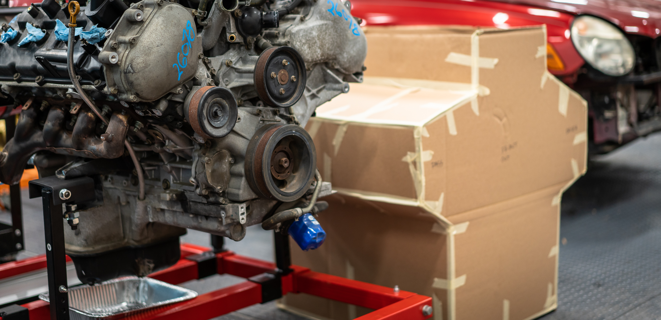
Having rolled the engine "in place" on the stand next to the car, I realize there will be a lot of taking the engine in and out for fitment. I've seen foam replicas of domestic engines that you can buy for this exact purpose. In fact, they even have threaded holes for things like accessories and headers to be bolted up. Seems like something that might be handy.
The problem is, they're very expensive. Like $500 and up. Not to mention there aren't any VK56 replicas available.
So I thought, why not try to make my own? Not necessarily with all the bolt holes, but with matching exterior dimensions to be able to throw in and out of the engine bay as I cut and sew the car. $20 in cardboard and expanding foam later, I got started.
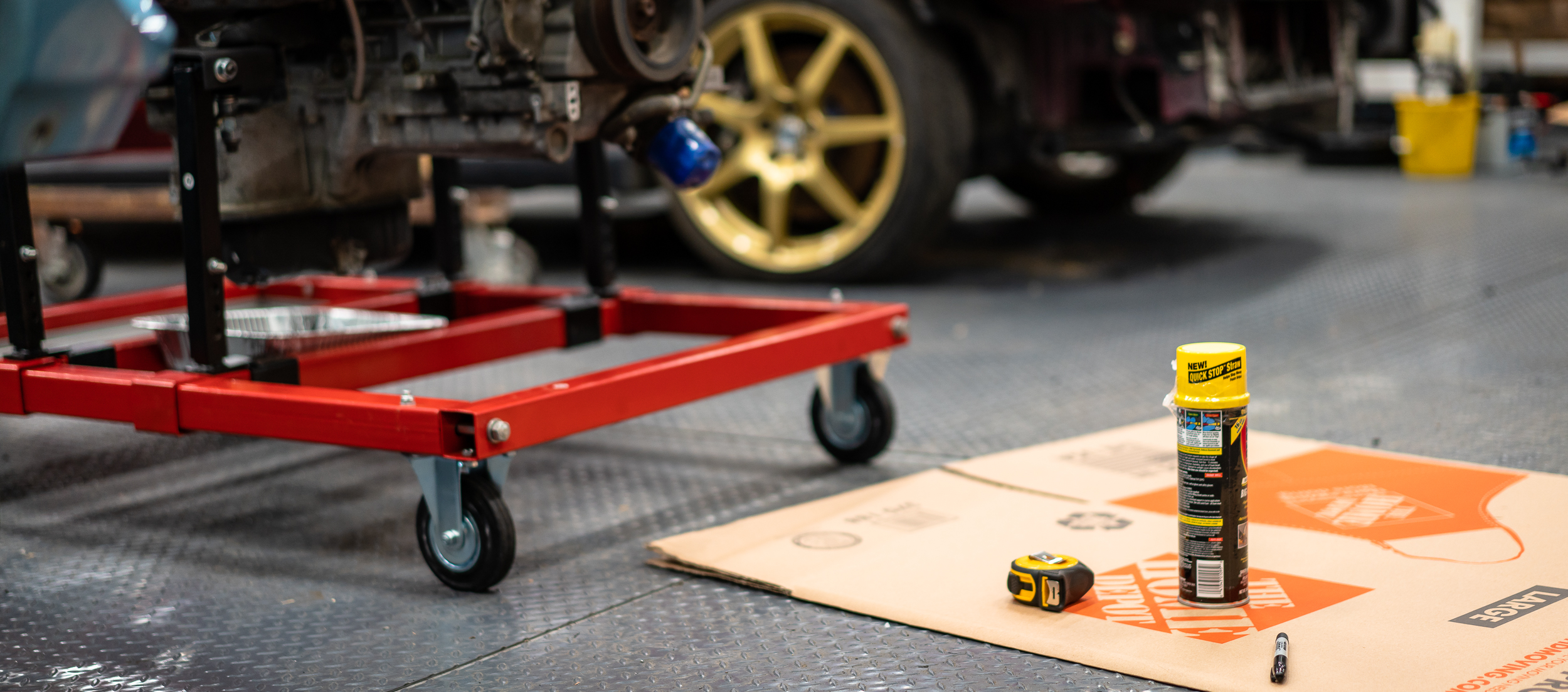
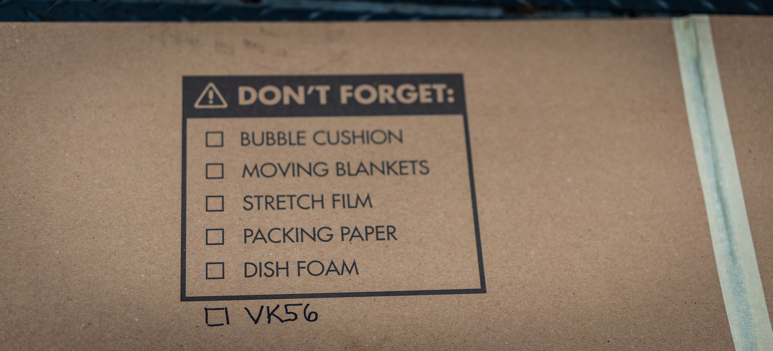
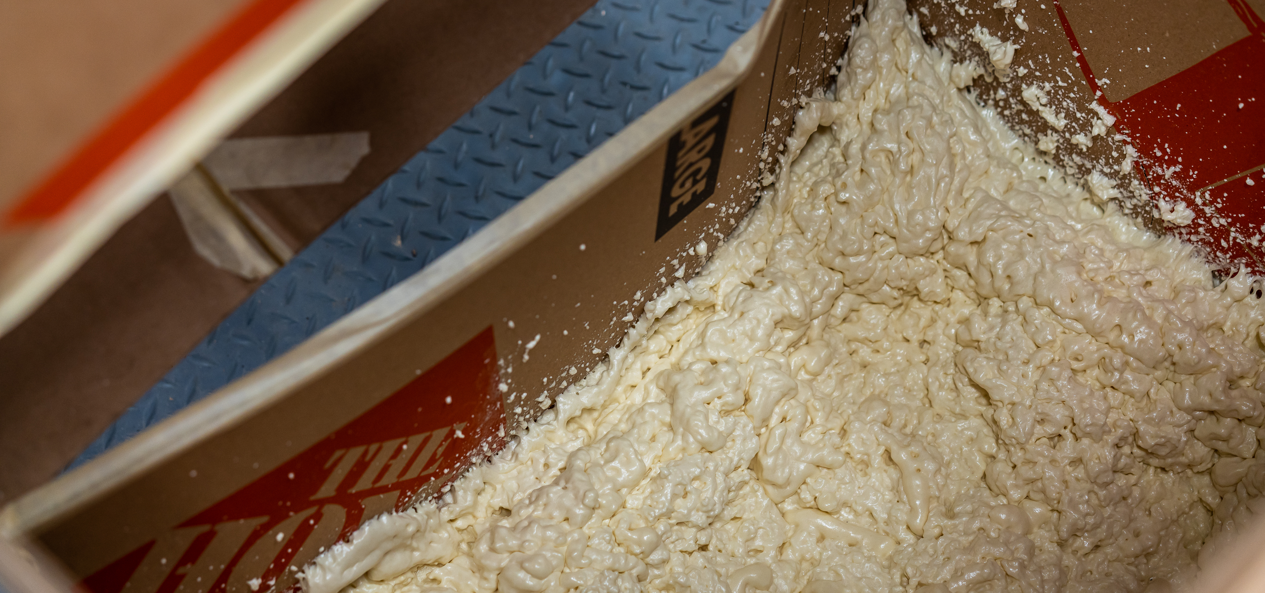
I bought a few Home Depot moving boxes and 3 cans of "Big Gap" expanding foam.
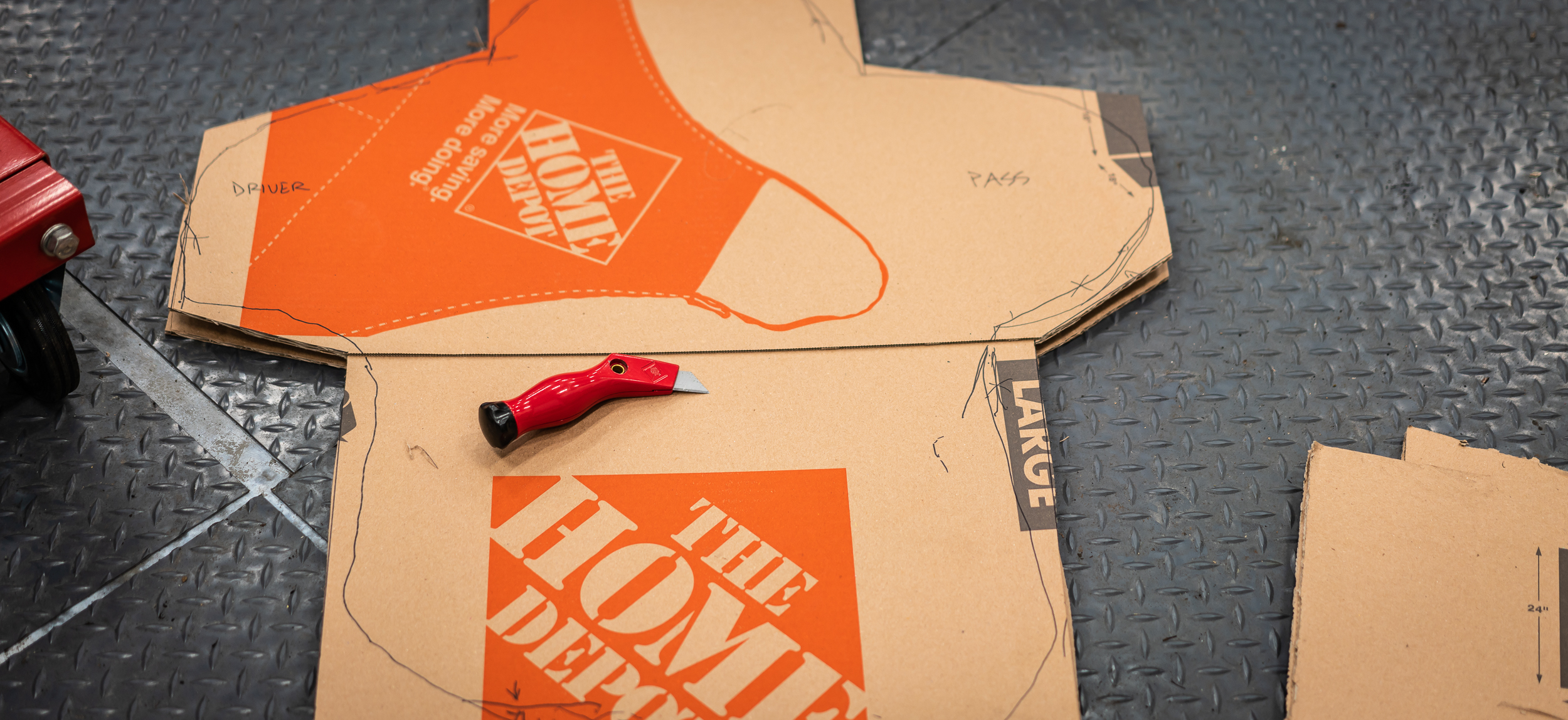
I taped one of the boxes to the front of the engine to trace the front silhouette.
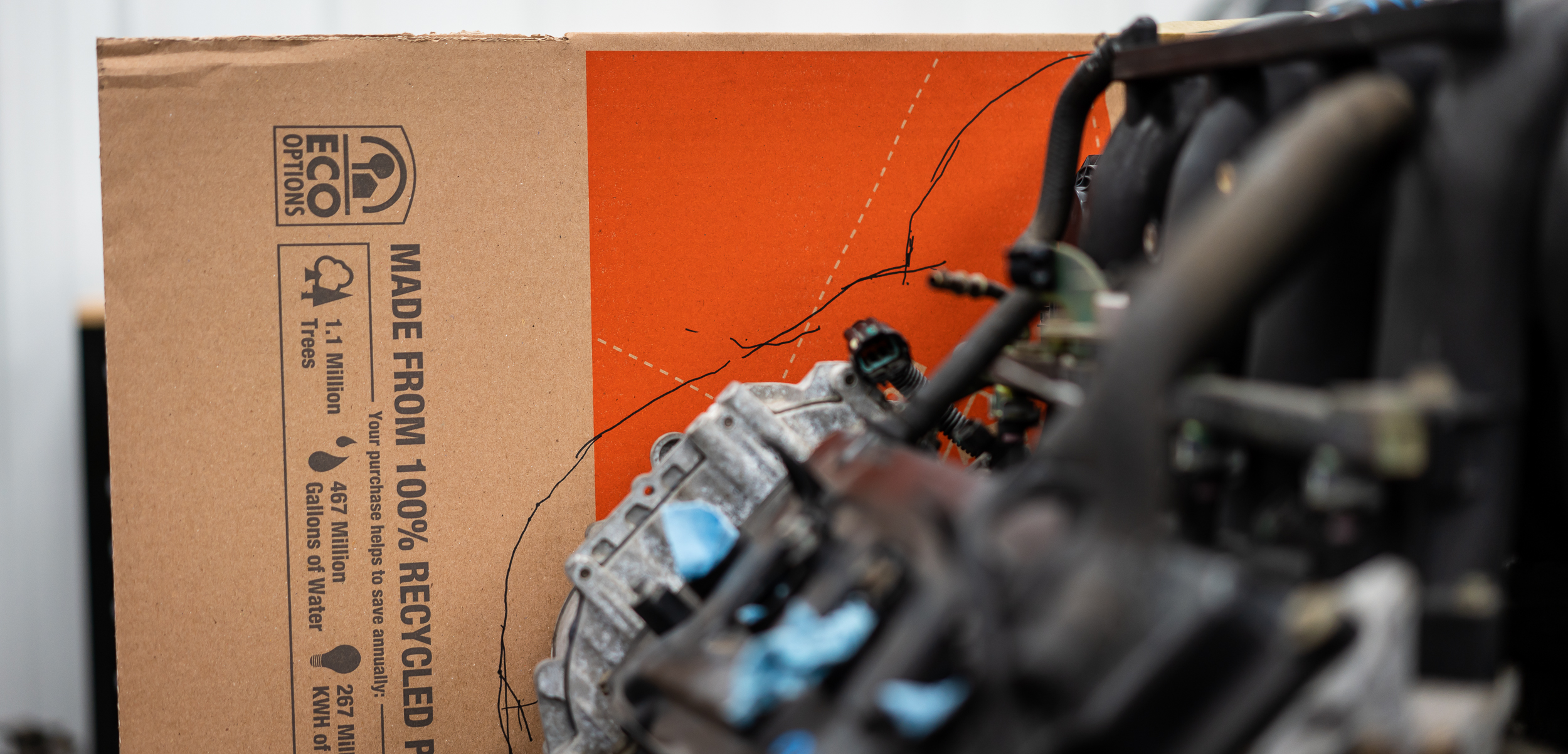
It's not rocket science, but I still spent and hour or so with a box cutter and some masking tape to get an approximately shaped box to fill with foam. I'll carve it down to exact size once the foam has set.
I took it outside to do the foam fill.

Now, I've used this expanding foam for its intended purpose around the house quite a few times. I've always found it a little bit of a bummer because they're essentially one time use, and I feel like I use about 1% of the product and throw the rest away. I really have no idea how much foam is in a full can. I thought 3 would get me close.
Ha.
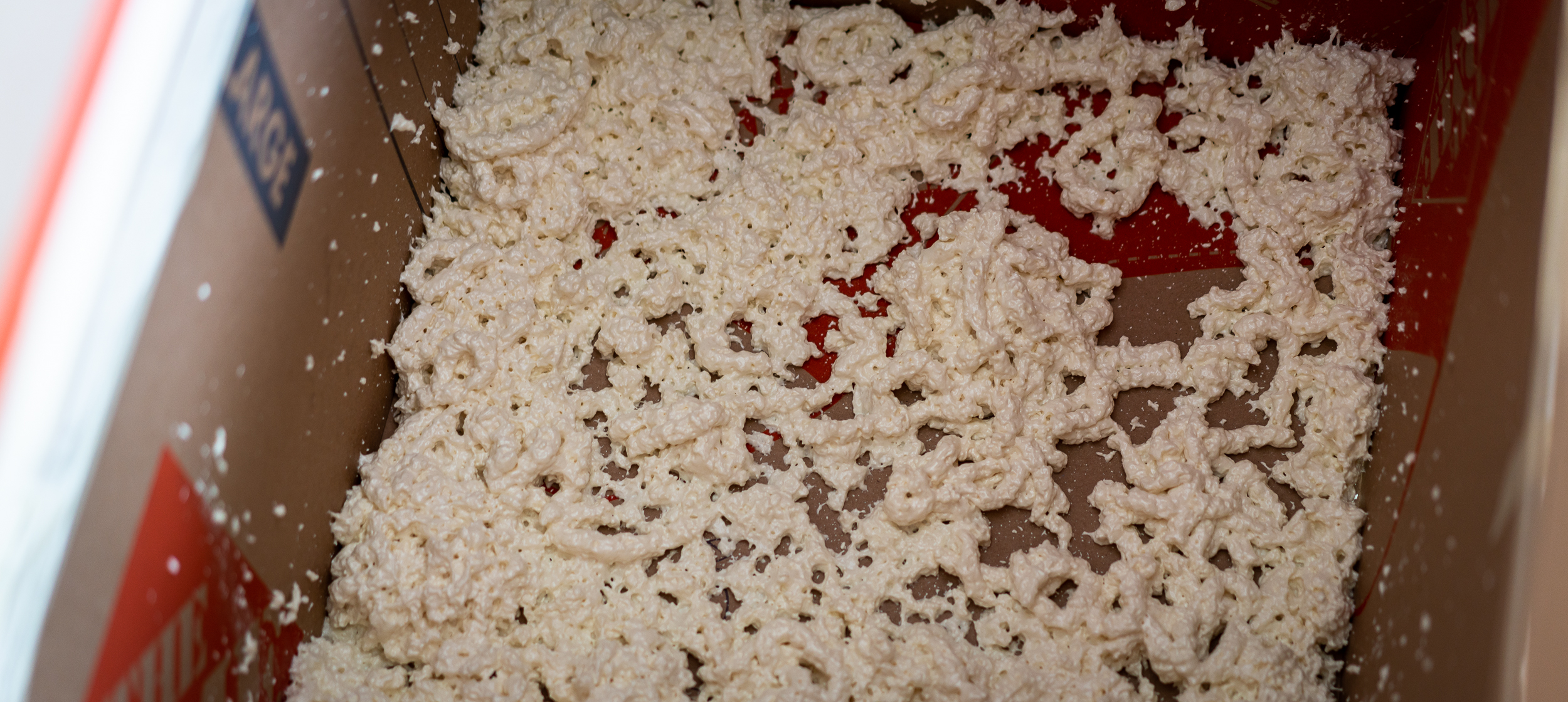
That's the coverage I got from 1 full can. Turns out there isn't magically 3 cu. ft. of expanded foam in each of these cans. Oops. 1 can didn't even cover the bottom piece of cardboard.
At < $5 per can, I finished spraying all 3 cans in and letting them expand to see where I ended up. That way I could see how many more cans I might need.
I was not excited to see how much volume 3 cans filled.

I'm not feeling too optimistic about this. Is it worth $20? Maybe, and it's fun. Is it worth $100? Eh, I'll have to think about it a bit more.
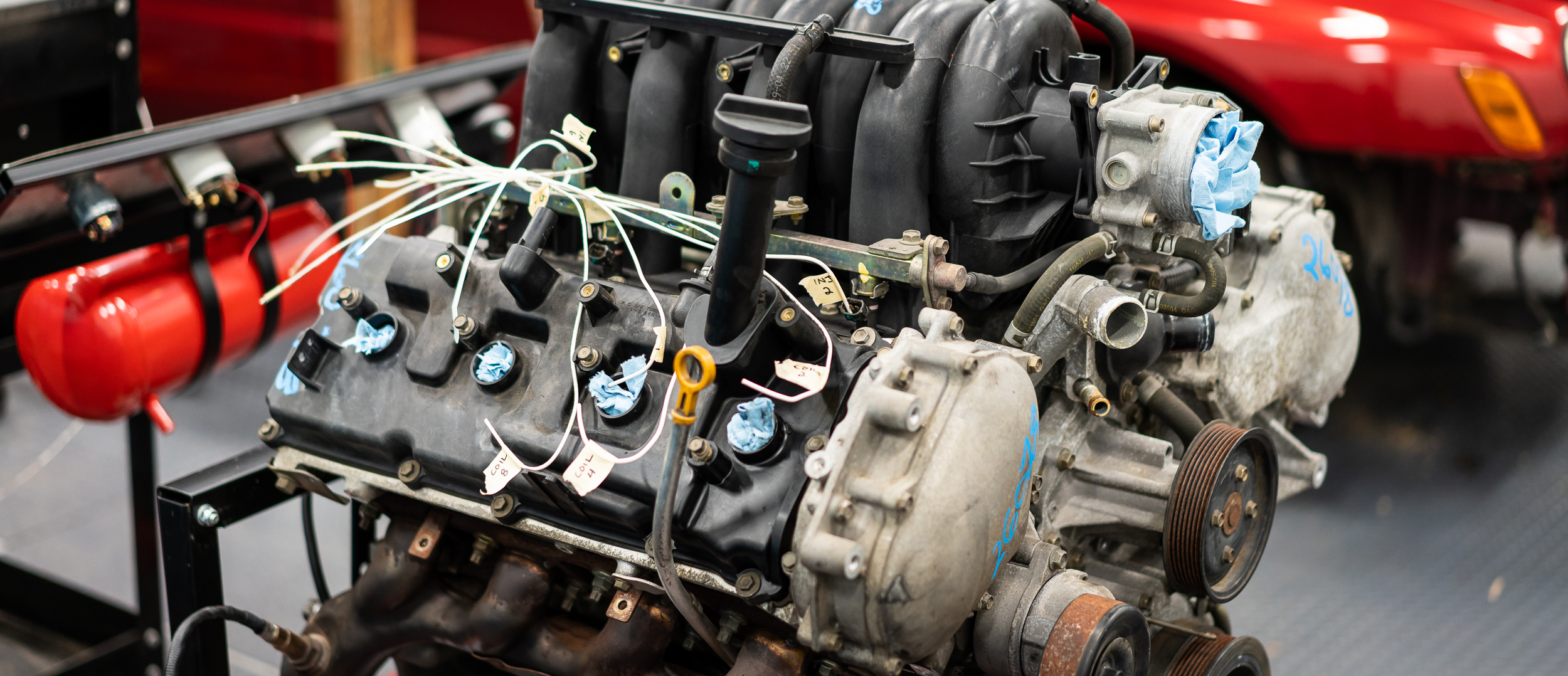
I moved on to finish the wiring template (templating?) for the passenger side of the engine. Just running the 14ga solid core, cutting at the back of the engine, then labeling. I'll take them home and work on the wiring harness in the comfort of my home. Or more importantly, the a/c of my home.
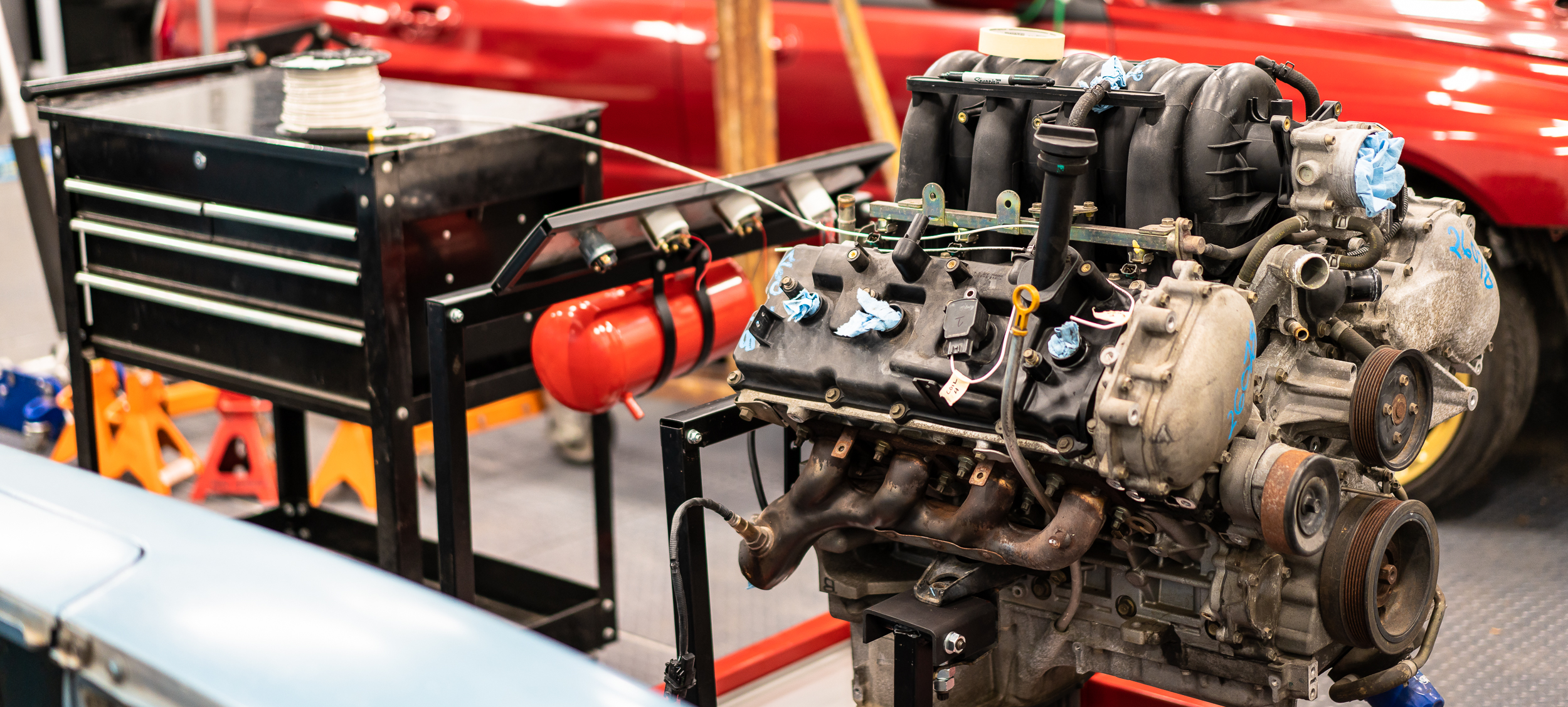
Happy enough with that progress, I moved over to work on the Saabmarine for a bit.
I really have to get to work on the wiring harness, but I've been bad about carving out time away from my wife and children at home to get that done. As I suspected early on, I may have to use shop night to get the wiring done. While it's not a/c'd, it's about the only way I can see to have a lengthy focused session. I'll give it one more shot at home, but if I can't make progress in the next 2 weeks, shop wiring it will be.
Beyond that, I have some bits and pieces to sort out before I can start the motor: water routing, radiator, serpentine belt, crank trigger wheel/sensor mounting, new cam sensor, some cheap mufflers/exhaust tubing so I don't go deaf, etc, etc.
Then I might be able to start plotting out where this whole thing will live.
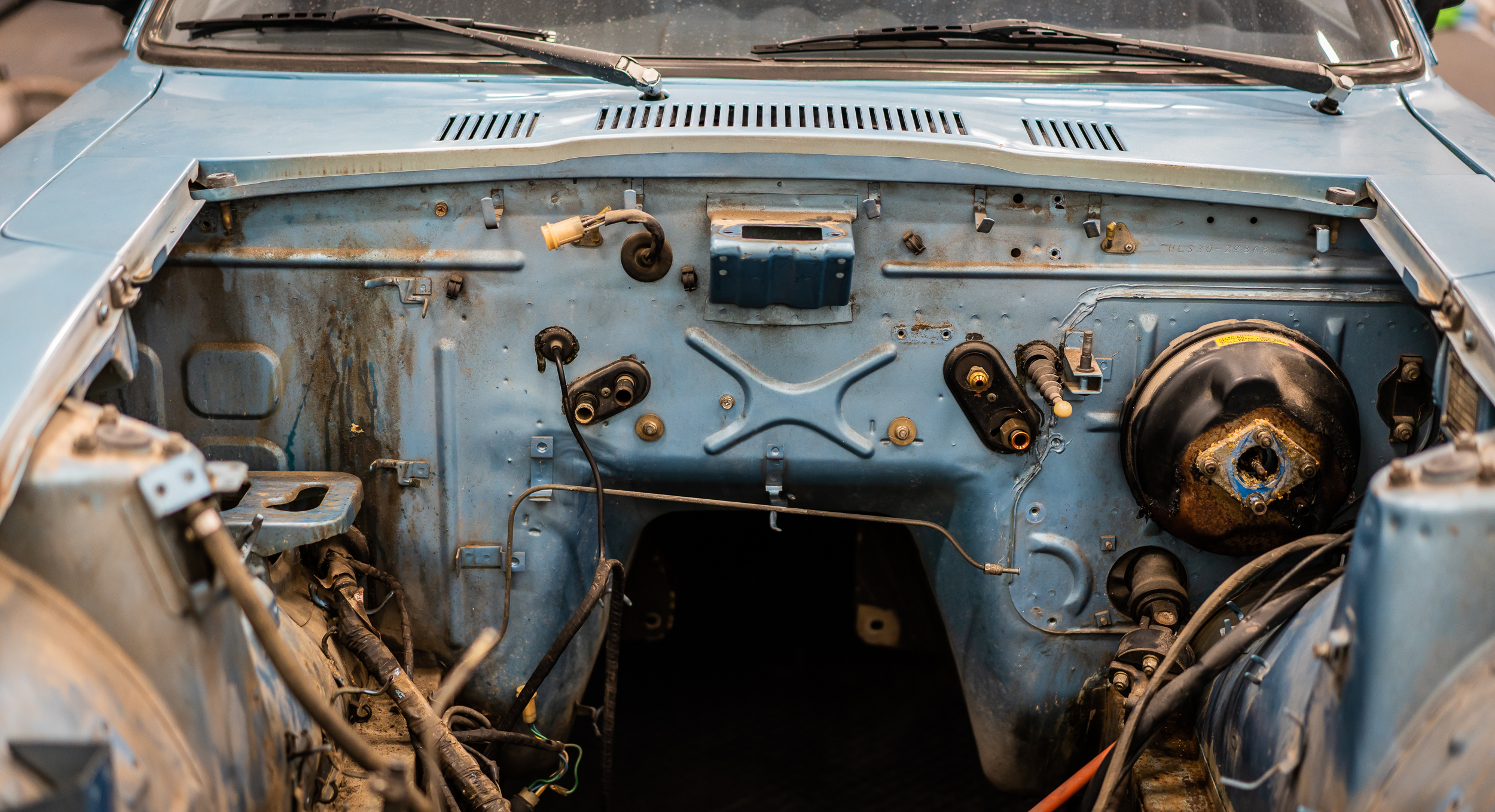
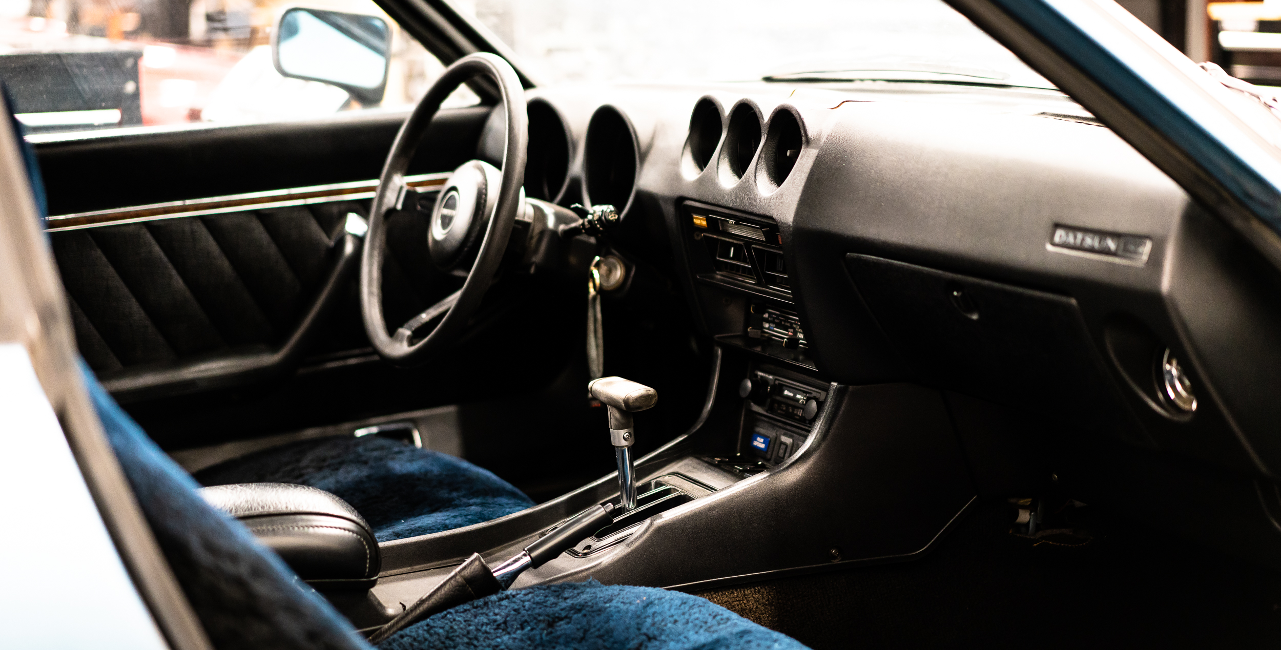
And I guess I'll have to pull out the interior to do that. I'm actually more sad about pulling this interior than I am about chopping out the firewall. So many memories, the old familiar smell, fuzzy seat covers...I think there's something in my eye......
The show must go on I suppose.
Oh, and for those who say this car is too nice to cut up for this project:
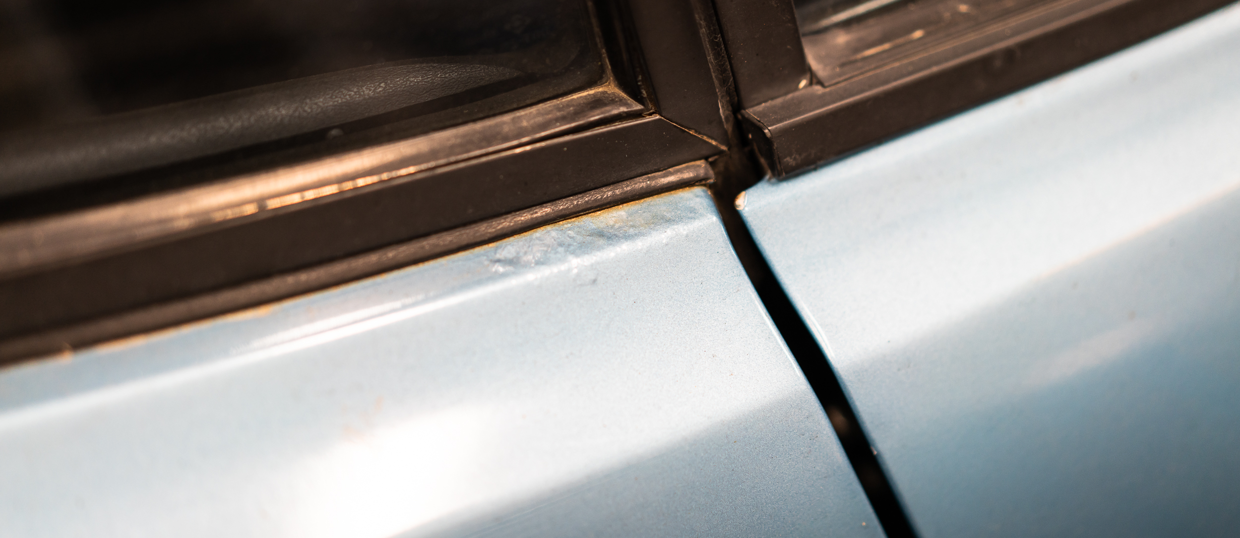
Pretty sure that's rust under there. This thing is scrap.
damen
It's going to be a good weekend there's a Friday update on this thread! Pictures are amazing quality as usual.
I like your "block" you made, there are 2 part expanding foams that can be purchased in larger quantities that are often used for filling boat hulls. You southern boys are spoiled with your definition of rusty.

Being from New England I laugh at your rust....followed by a good cry.
For the box what if you just spray foam the seams or just the flat surfaces to make the shape more rigid instead of filling the whole thing? That way you would save foam.
In reply to Ram50Ron :
Thanks, amigo-
Good call on the boat foam- I found that stuff too after failing with the expanding foam. It looks like about $50 to maybe have enough to finish this. Not sure if it's worth another $50.
What do you think? Will it be that useful?
Who knows how bad the rust is until I grind it back though, right? Could be a rustberg situation- after all, this really is a Central California car :)
In reply to PseudoSport :
Also a good idea, the only issue being that the cardboard is not the final shape. The cardboard is just to hold the foam in an approximate shape while it sets. I was planning on stripping the cardboard off, then carving the foam block to the final dimensions, which are a decent bit smaller than the box.

Spray foam on walls aboutb2 inches thick, throw in packing peanuts for filler in the center. Spray foam on top, locking in peanuts.
Think of it like a twinkie. Nobody gives a E36 M3 whats inside as long as it functions like a twinkie.
You could also put a box inside the box and spray foam around that. 2-3" layer of spray foam on all 6 sides, less foam and then you don't have to play with the devil that is packing peanuts.
Wait a minute. I just realized what you are actually doing with this. You're essentially "casting" a blank and then you're going to whittle it down. At that point why not get pink insulation foam and create a low-res layer model and whittle from there. That foam is pretty cheap, you don't have to wait for the expanding foam to cure and then you wont have foam on your knuckles for the next 3 weeks. See below.

In reply to Dusterbd13 :
Good idea. I might go with an empty box in the middle and then pour 2 part foam around it, rather than try to spray the walls. The spray stuff comes out in a tube, rather than an nice spray you might get from an insulation gun, so it's not too conducive to the spraying I think you're referring to.
In reply to Ram50Ron :
Yes, I like the empty box idea. I originally was going to do stacked boards of foam, but with the longest dimension being 29", I'd have to buy 4 ft x 8 ft sheets instead of the nice 2 x 2's, and those are surprisingly expensive. I think empty box + small 2 part kit around it is my favorite idea. Although, I'm now second guessing how useful this particular lump is going to be...
Small update.
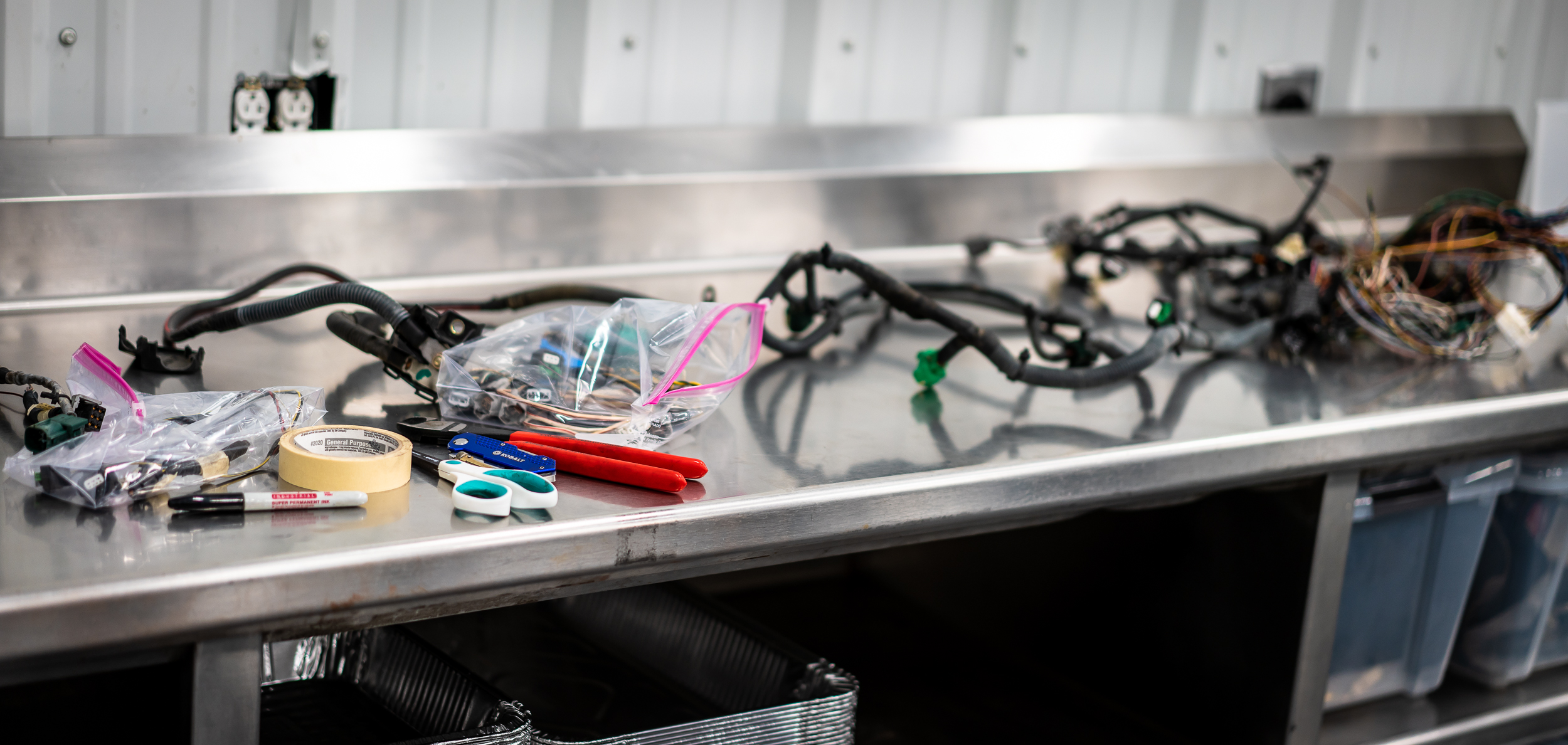
Some time magically appeared this weekend when Grandma came to visit. I was granted permission to hide away for a couple hours with my mess of wires. I had casually set up a table and some tools in our master bedroom (!) for this project, so I first took stock of everything to get mildly organized. I would prefer a table about 4 times this size, but I certainly won't complain. The a/c is mighty fine.
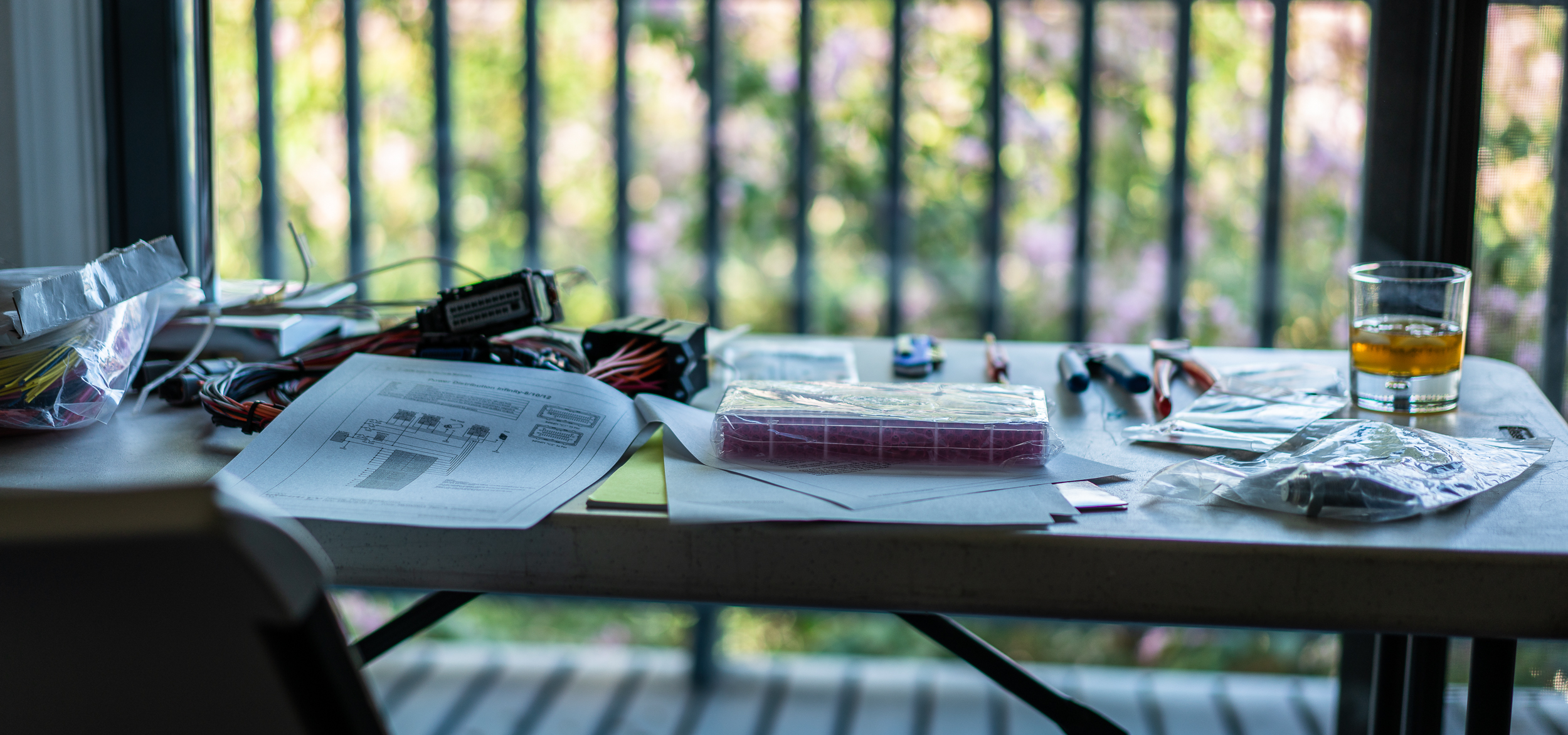
Now, I did cheat quite a bit by ordering a starter mini-harness from AEM. I did that for a couple reasons.
First, I've never made a wiring harness, so any head start is going to cut down on my time-to-completion. Not only is it a head start, but it's also an example that I can look at and possibly copy going forward.
Second, this harness will not be the one that I use in the final version of the car. It's a practice harness that is primarily for the test stand and maybe some testing in the car, so I don't have to worry exactly what kind of wire they use or whether or not it's a "best practice" "gold standard" deal (it's not). I can worry about that later. It takes some pressure off knowing that it's just for practice, so hopefully I can move forward without getting mired in analysis paralysis, which seems like it would be easy to do in the land of automotive wiring.
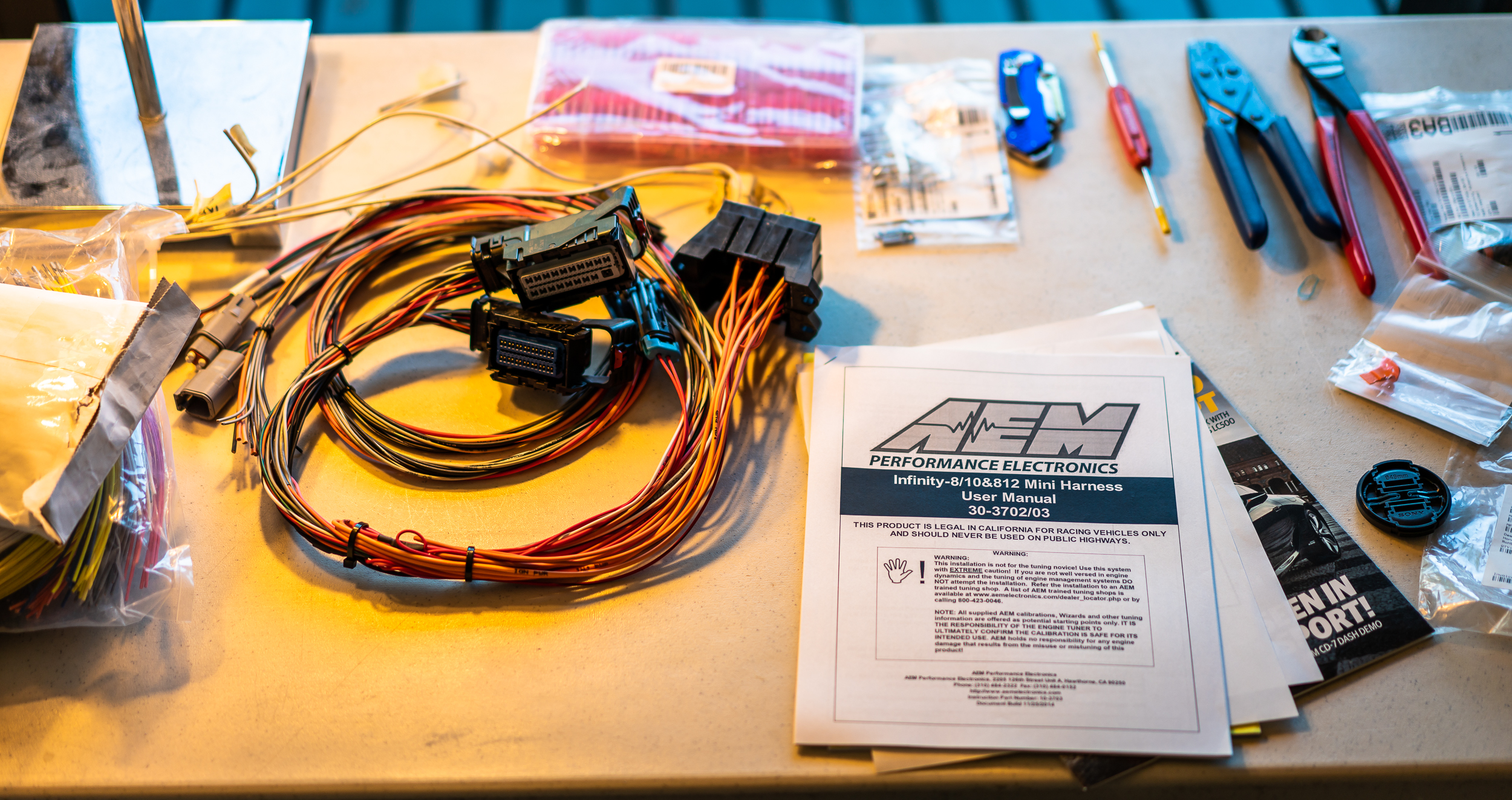
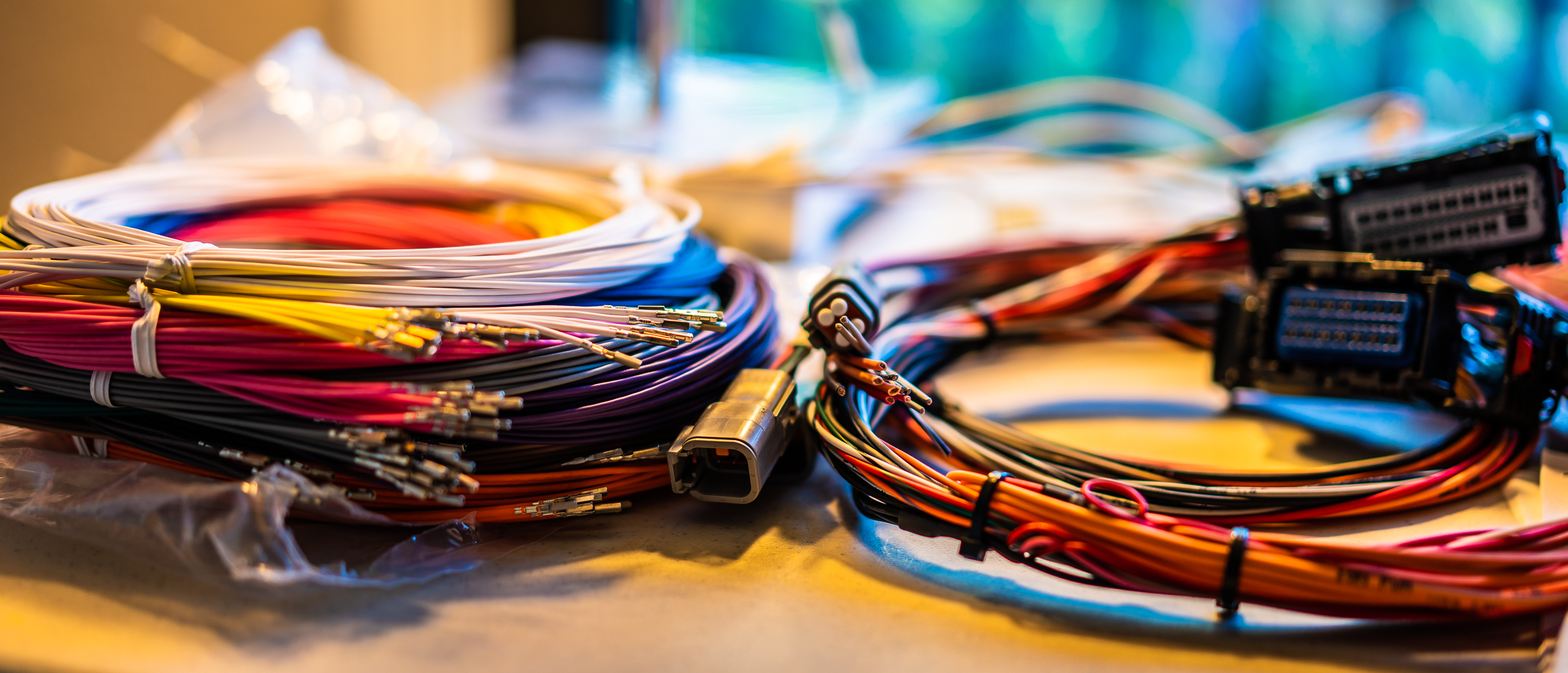
The one that I got came with 100 8' long pre-terminated 22ga wires. Cheating for sure. Apologies to my man Phil at RYE, who won't accept anything less than MoTec/Spec55/Raychem/ConcentricTwist. I hope we can still be friends.
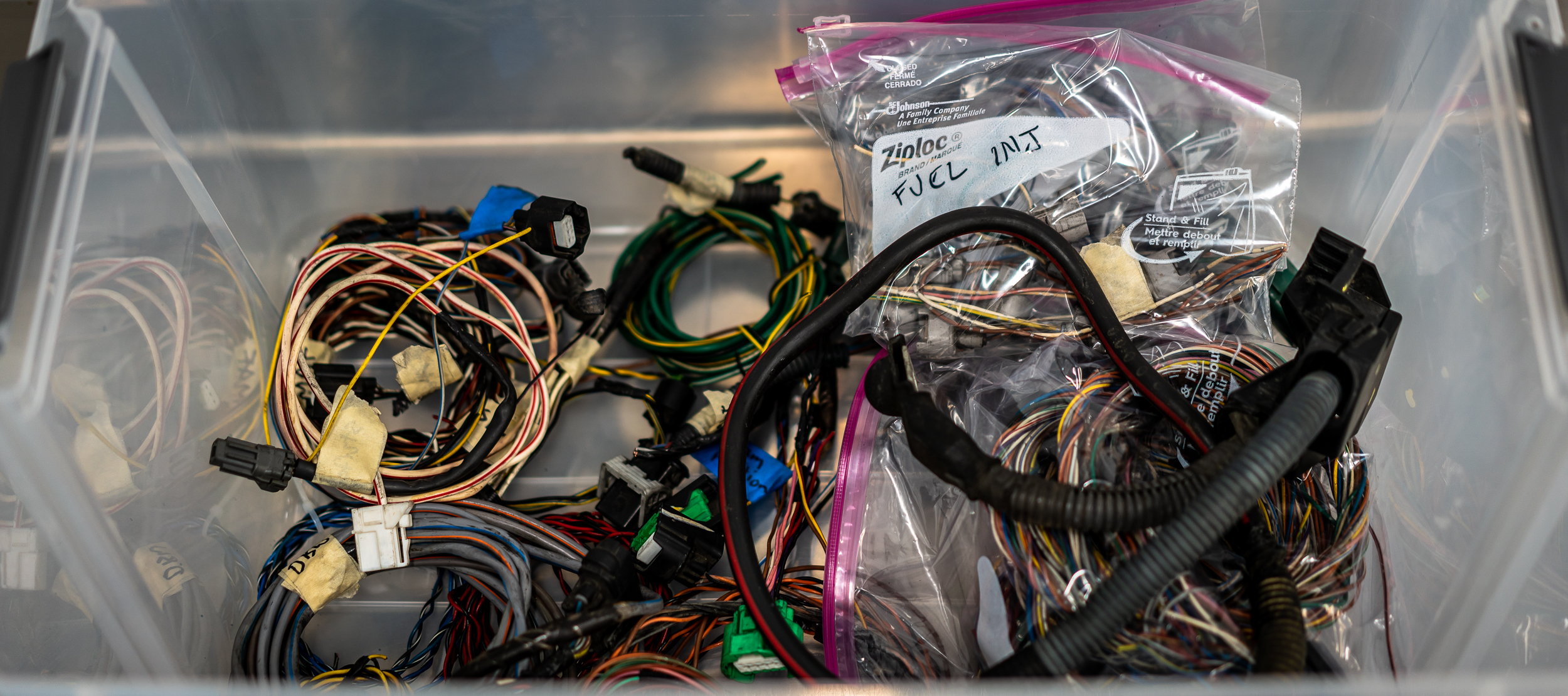
Because this is just for the stock motor on the stand, I bought a junkyard pull-off harness from a 200x Titan to harvest for connectors. I think the injectors and coils I'll be using for the full engine build use different connectors than what's on the stock motor, so it didn't make much sense to me to buy all new stuff.
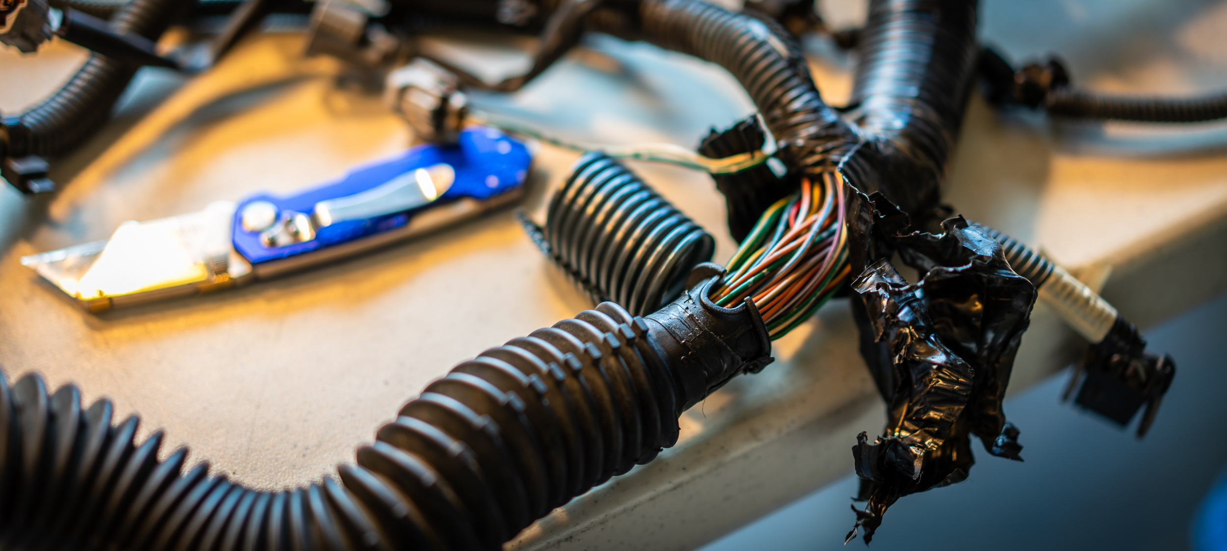
Having no experience in wiring harnesses, I also thought it'd be a good opportunity to dissect an OEM harness to get a feel for their construction methods. Here it is with the "wire-length template(s)" in a box.
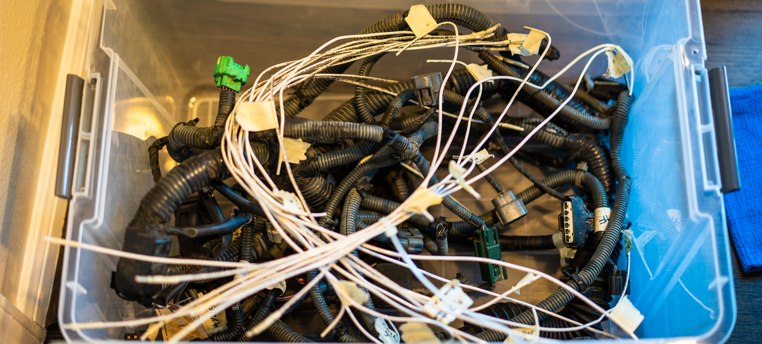
And all laid out. It's really a dirty, greasy, old-electrical-tapey mess.
I figured I'd start by getting all the connectors off that I needed.
I couldn't really think of how a smart way to start, so I just started with the injector connector closest to me.
It seems my desk job has given me pillowy soft and smooth fingers; tearing this old harness apart isn't particularly pleasant. My fingers hurt.
It dawned on me that the injectors are all fed +12V from one pin, then connected to ground via transistors in the ECU on the other, but I had no idea how to get power to all the injectors from one fused +12V wire.
8 -> 1 split?
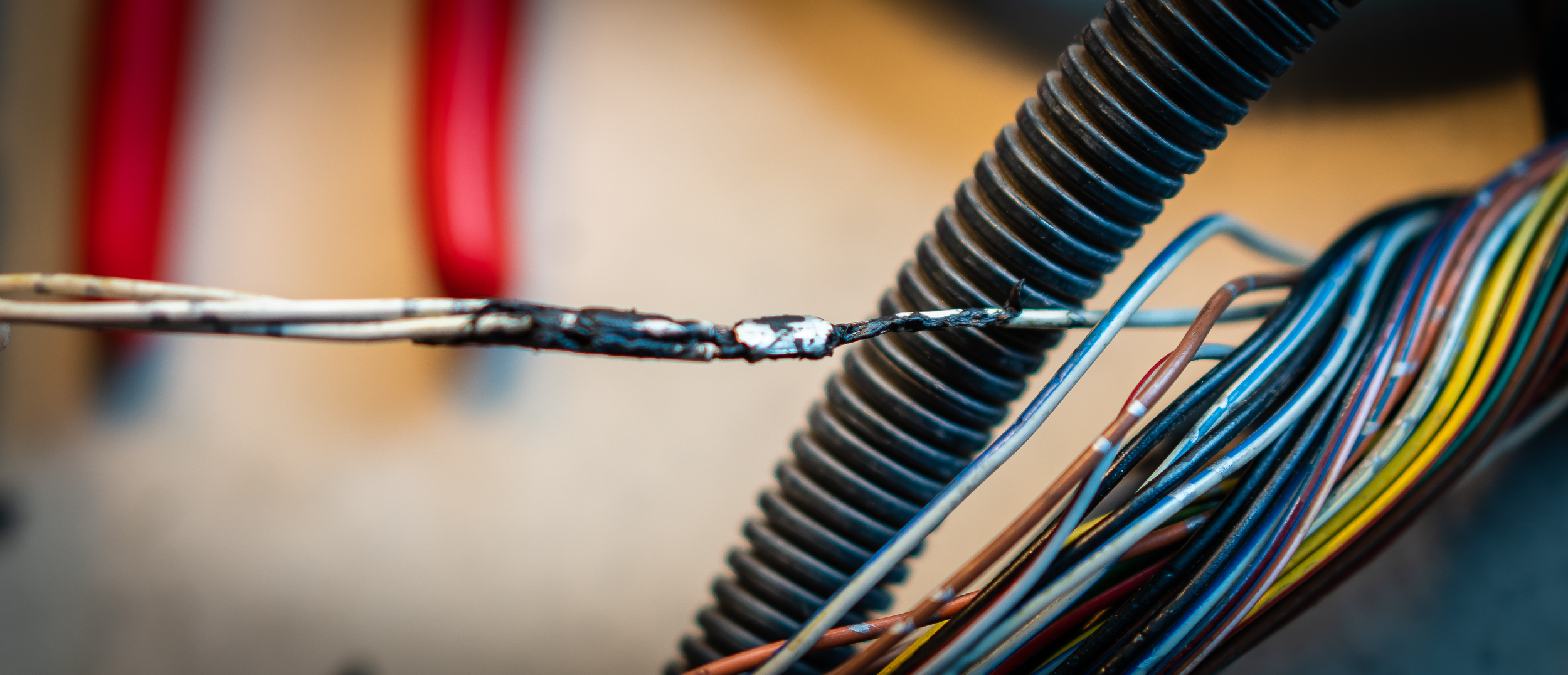
Since I had the OEM harness in front of me, I decided to track down how Nissan did it. It didn't take long to find a junction of 1 -> 3 injector power wires.
This was extra gross. 15 year old electrical tape wrapped around some clear wrap, wrapped around some nasty tar like substance, which was globbed around a 3 -> 1 butt splice.
Yick.
But mystery solved.
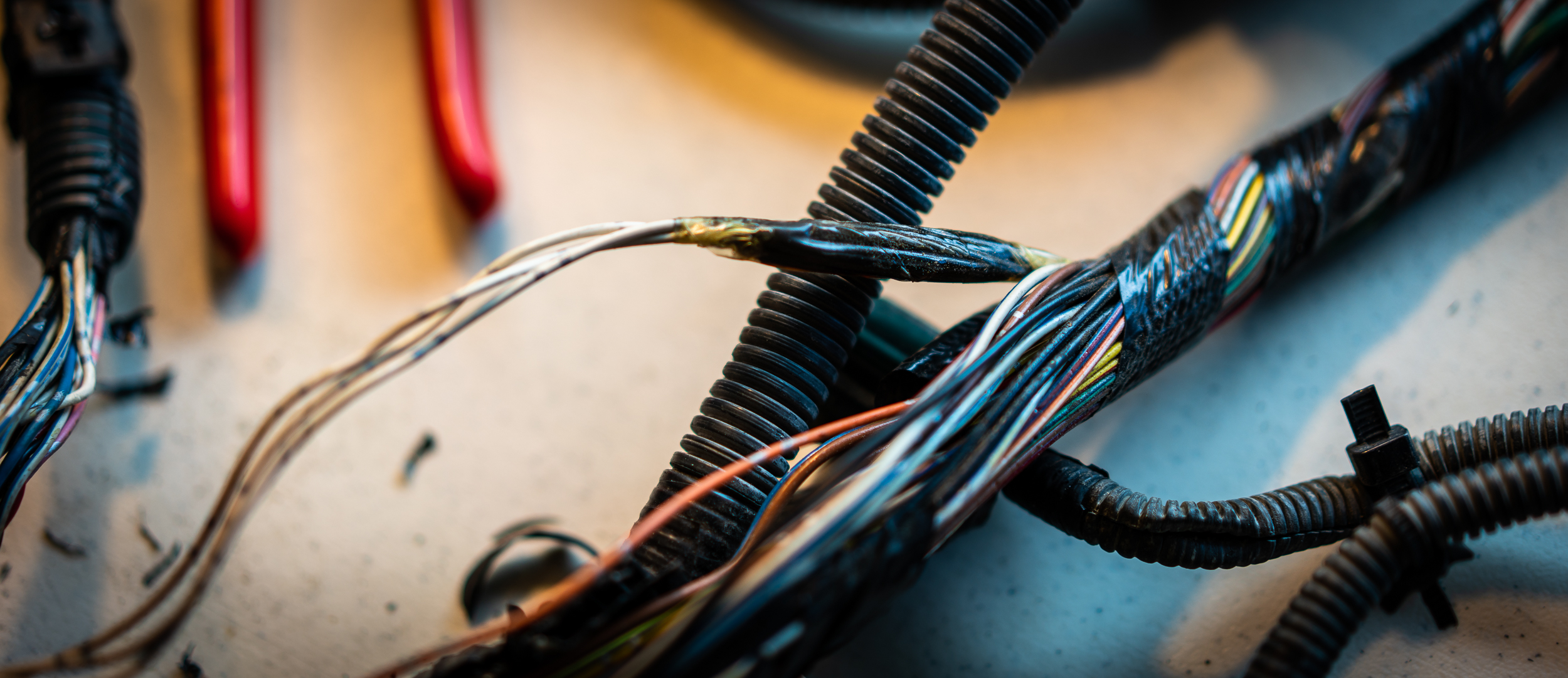
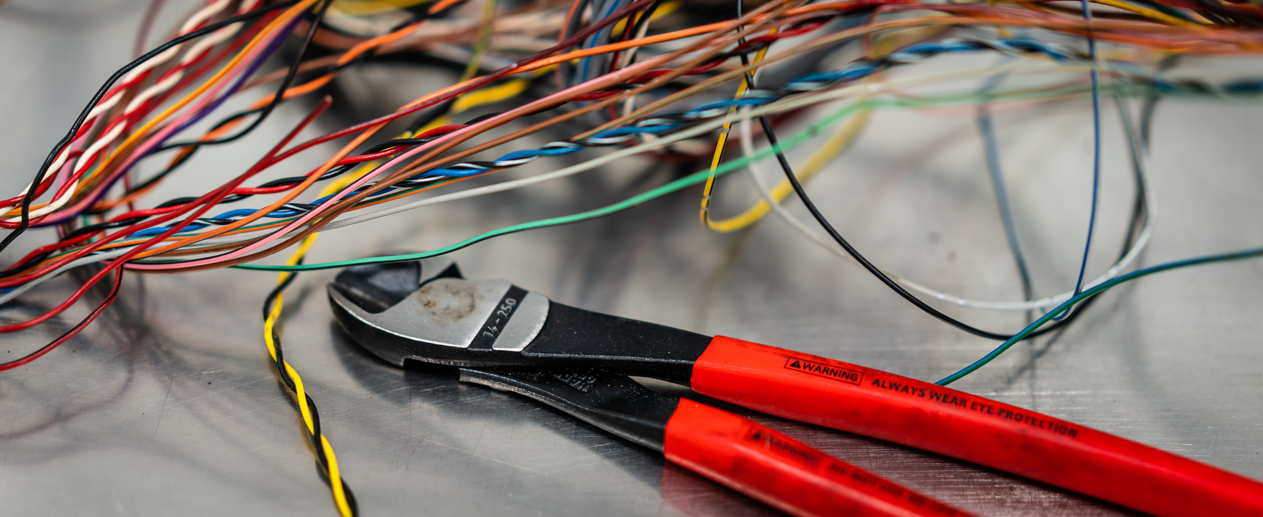
I just slowly worked my way around the harness, cutting, unwrapping, cutting, unwrapping, cutting...
Every now and then I'd snip off a connector with about 4" of wire to splice onto the test harness later. Not terribly complicated work, mildly soothing even, apart from the greasy mess and sliced up hands from that corrugated conduit.
My time ran out, but it was really good to get a start on this. Back in the box for later.
damen
I returned to the foamie experiment to find that the foam had shrunk a considerable amount, pulling the box-model apart. I don't want to waste any more time on this, so I filed away the lessons learned (put a box full of air in the middle to take up space, use 2-part boat foam) and pitched it.
Concerning the wiring, as I feared earlier, I wasn't able to adequately carve away time at home, so I hauled all my supplies back to the shop. It was worth a try.
I wanted to get some extra progress in, so I actually drove out to the shop very early on a Sunday morning and was working by 6:30am. A few hours of quiet wire work is a good task with some coffee and music.
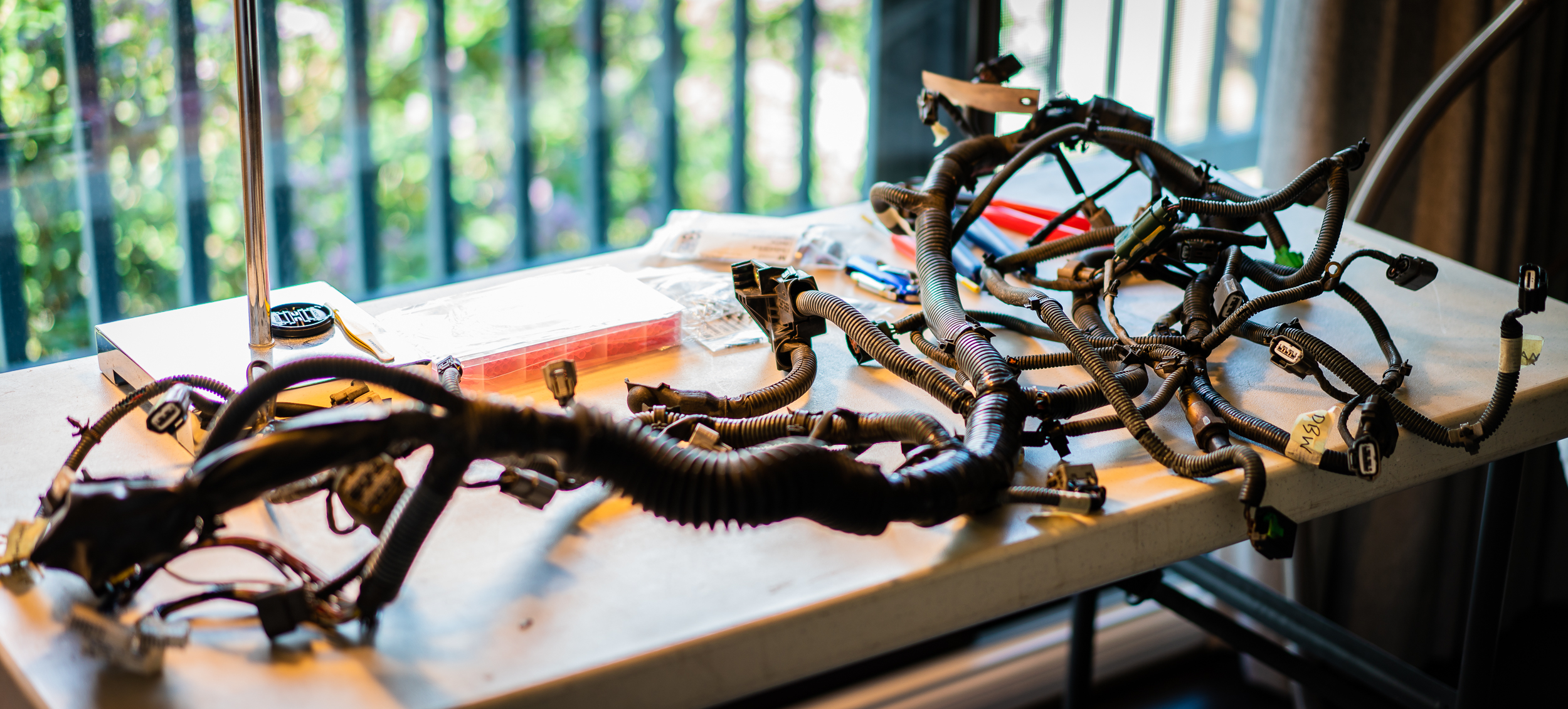
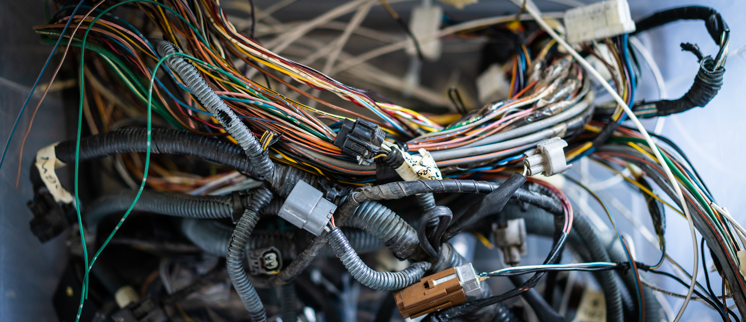
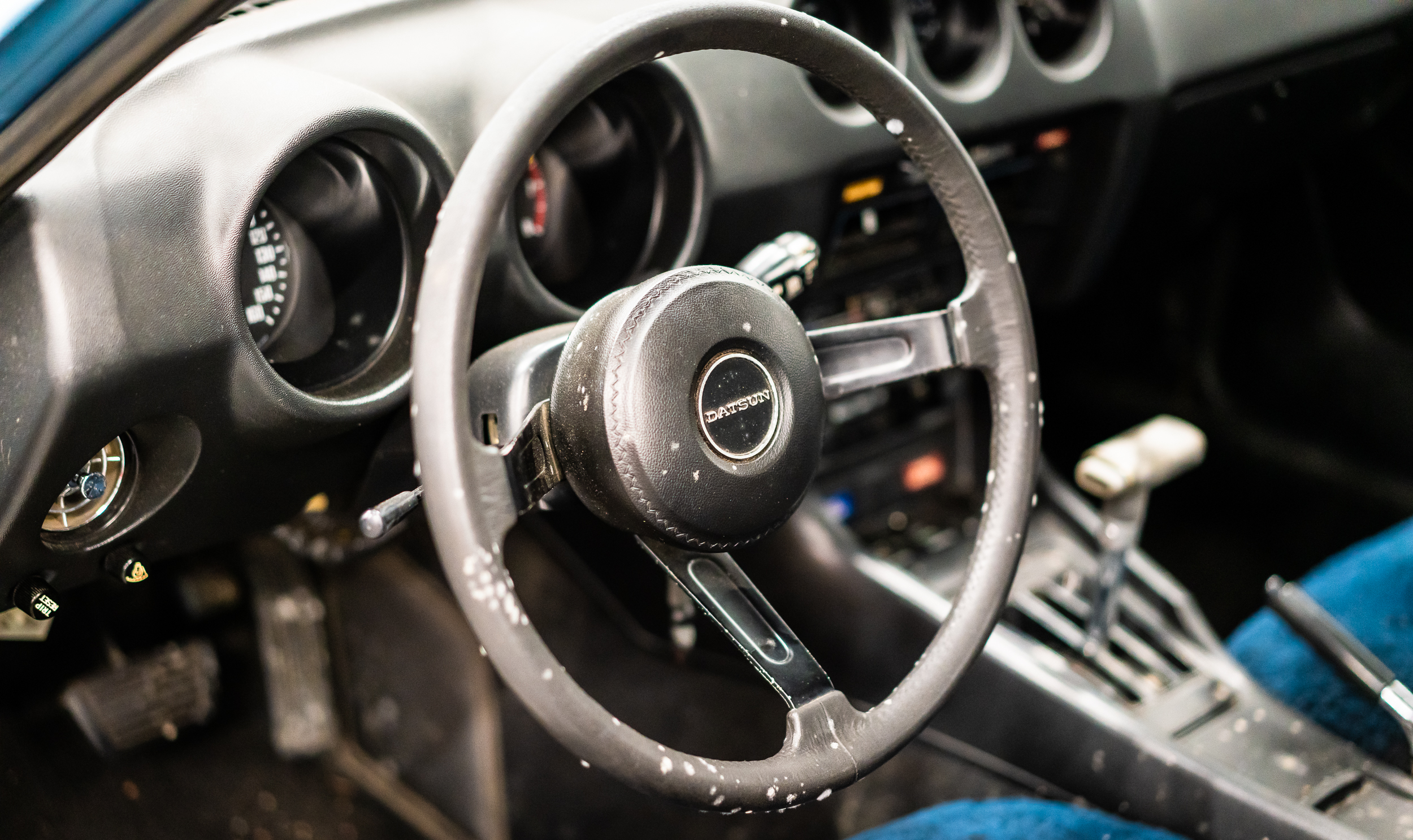
One benefit of being back out at the shop is that I have a beautiful table on which to work. I cleared and cleaned it before spreading out the OEM harness.
![]()
I know I've said it before, but it's pleasantly enlightening to see how these harnesses are constructed.
There are quite a few twisted pairs for the sensor signals:
Capacitors in series for the sensor grounds (low-pass filter?):

And shielded coaxial cable for the two knock sensors:

After a few hours of work, I had the OEM harness fully disassembled and organized. I now have all the connectors I'll need to get the stock motor running on the stand, along with a lot of decent amount of spare wire to use where suited.
I won't miss the 15 year old electrical tape and corrugated plastic sheathing.

That was it for the morning, but I was happy with the progress.
I returned another evening to work on the motor on the stand.
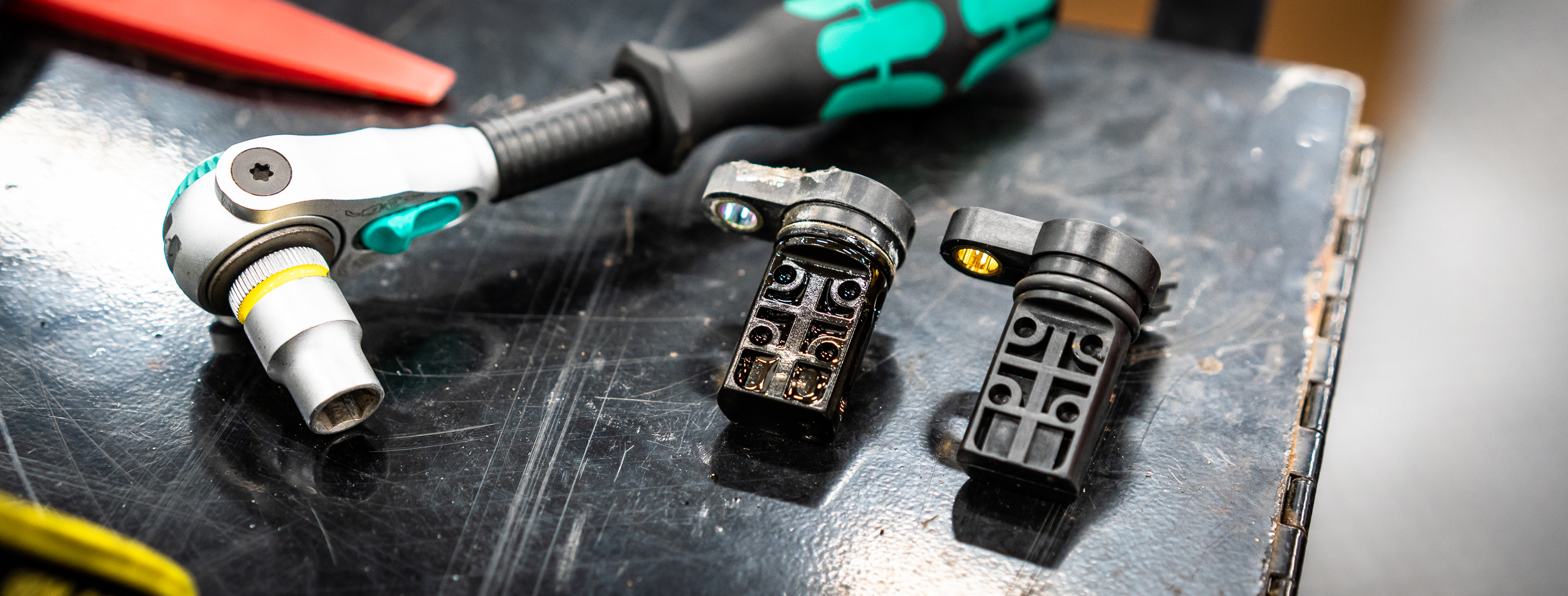
The motor came with a broken cam angle sensor.
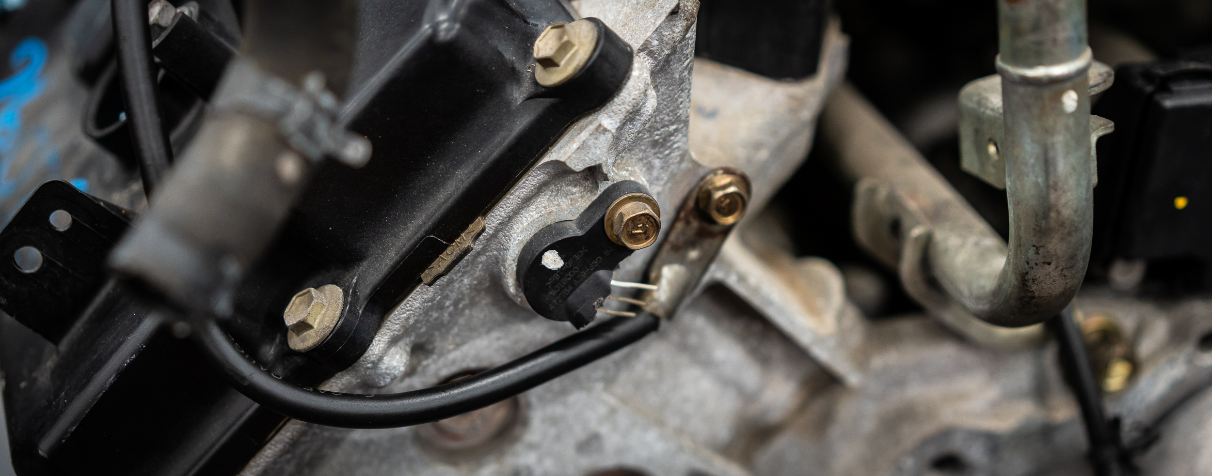
I ordered a new one and swapped it out. Old and new here:
One of the biggest issues many people have with standalone ECUs is cam and crank angle sensing. You can run just a crank angle sensor, but only in a semi-sequential wasted-spark configuration; the cam angle is need to run full sequential.
While I had the cam angle sensor out, I took a look at the notched wheel used to generate the signal:
I think this means it has 4 series of marks around the wheel, I, II, III, IIII. I don't know how happy the AEM Infinity will be with that setup (it seems the preferred wheel is just one notch at one spot), but I'll find out.
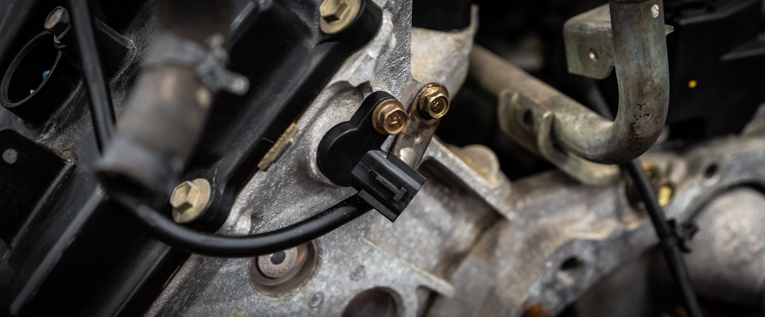
The new sensor went in without drama.
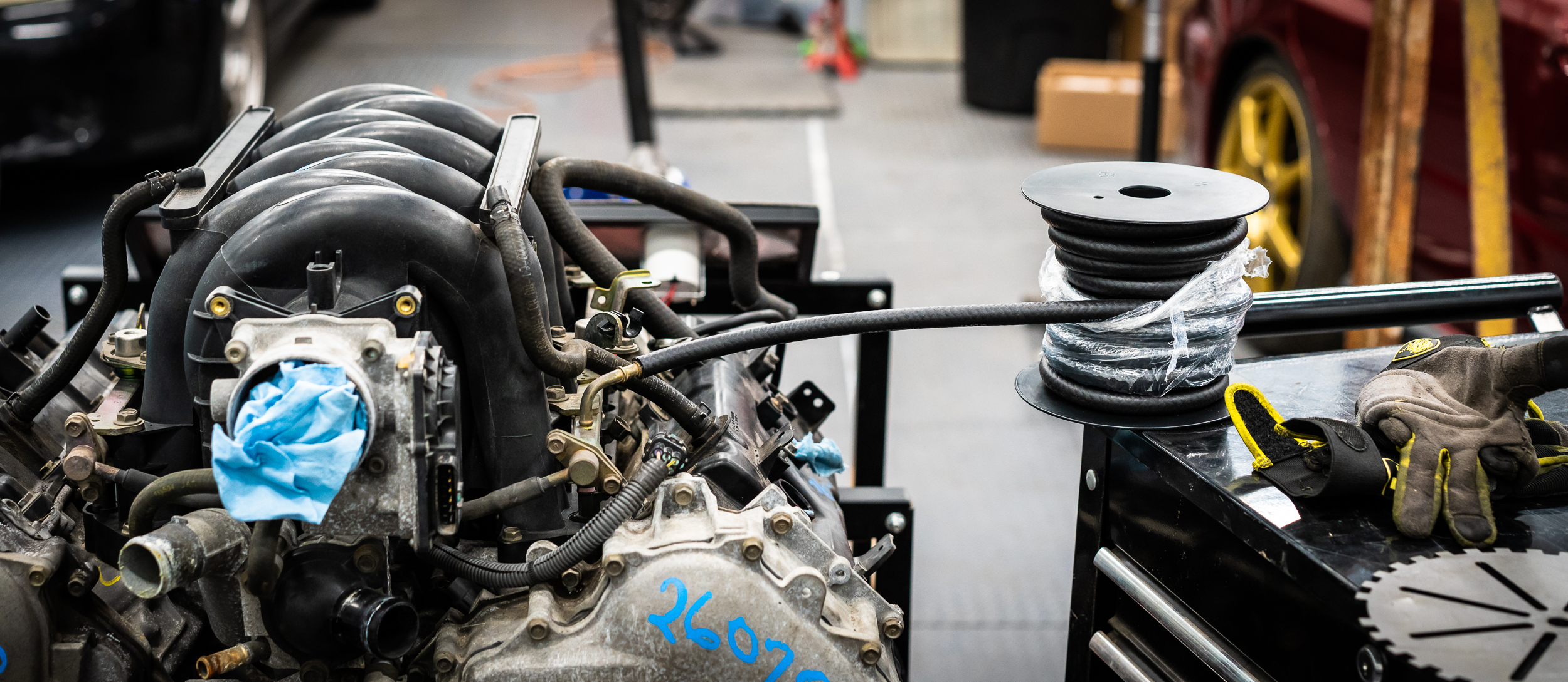
My shop partner, Nik, had a Deatsch Werks fuel pump on the shelf from one of his many past, present, or future projects. He's loaning it to me for the engine stand running. It fit right up with the batch of fuel hose I ordered. Woot.
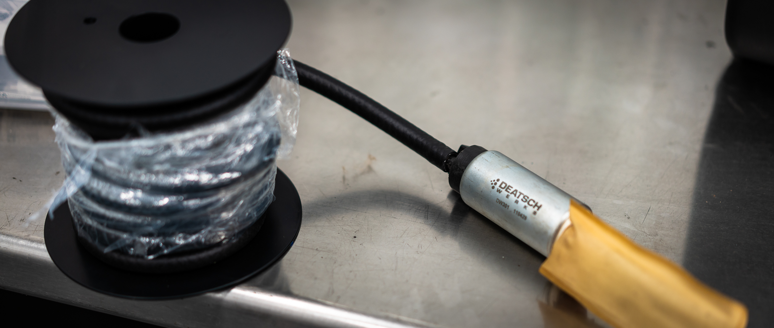
I test ran some fuel line to places it needed to go, mostly to check that I had the right size:
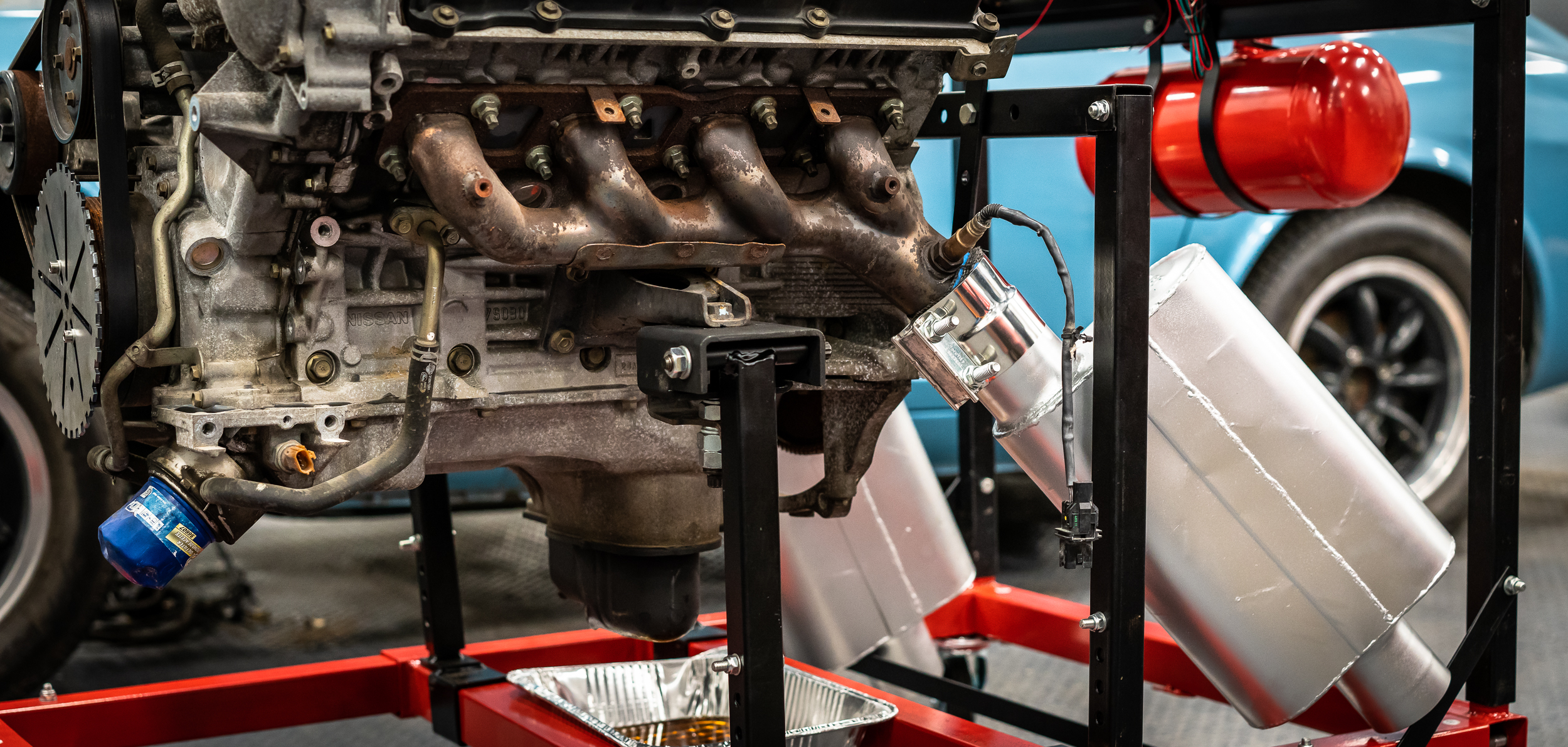
So the motor came with exhaust manifolds on it. Sort of.
The scrapper from whom I bought the motor used a sawzall rather un-judiciously to separate the exhaust before the integrated catalytic converters. So while I'm glad there is a manifold, if I ever get this thing started, it's going to be loud.
Too loud for my sensitive ears.
I perused Summit Racing's cheap mufflers and exhaust clamp stuff to see if I could get some mufflers semi-attached, hoping to quiet it down just a bit. They have a nice selection of house-branded 2-chamber mufflers for less than $30, so I got 2, plus some clamps, plus some header wrap to take up slack.
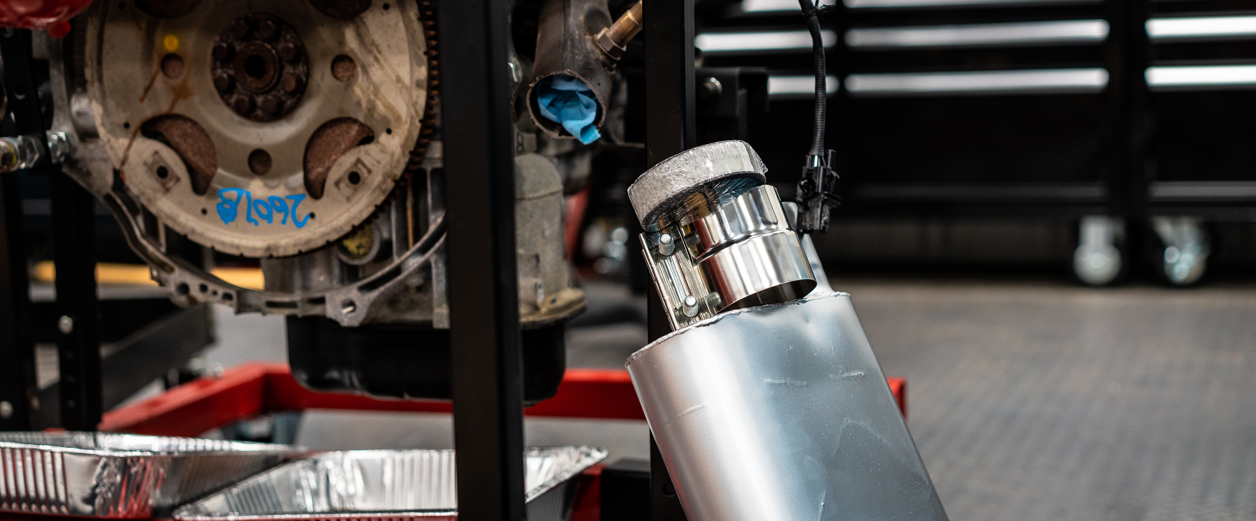
There's no flange or anything on the exhaust manifold, so I got some clamps to go from the sawed off stump to the 3" muffler. The clamp was a bit on the big side (on purpose), so I'm going to try a couple layers of header wrap beneath the clamp, for fitment. Big thanks to another racing friend, Kevin, who stopped by to lend a hand with this task.
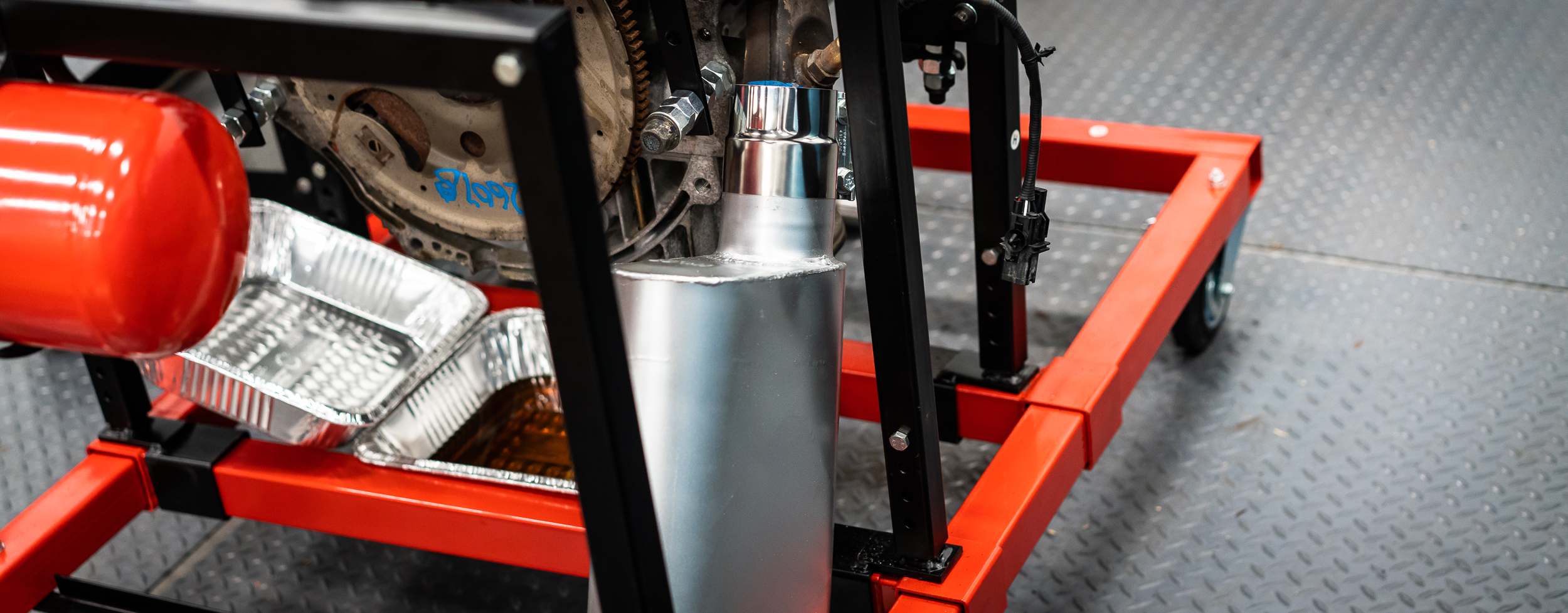
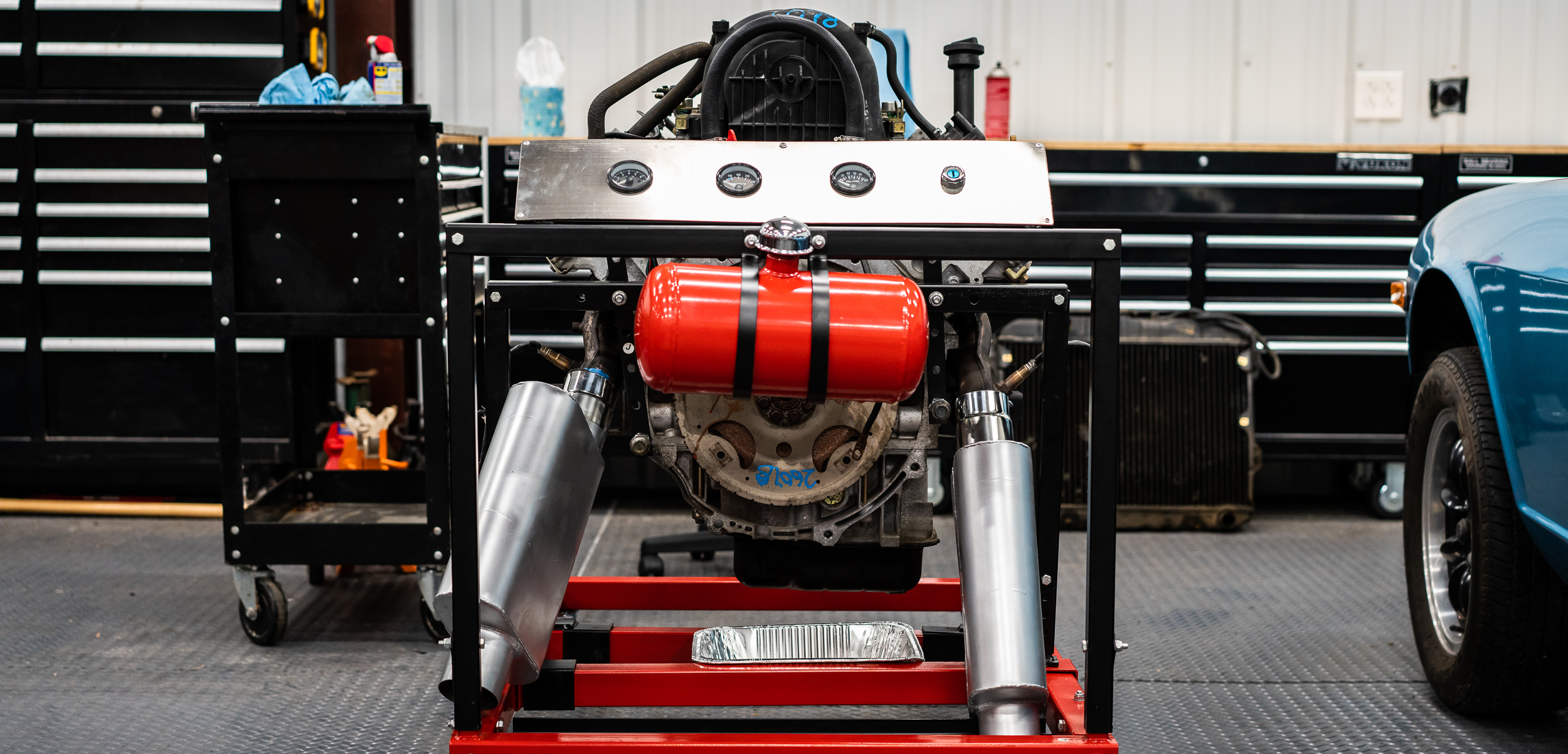
We got it all tightened up, and it seems to fit well enough. The muffler weight is supported by various legs on the engine stand, so I'm hopeful that this might work?
The manifolds are not symmetrical (nor are the junkyard cuts), so it has a bit of a goofy look.
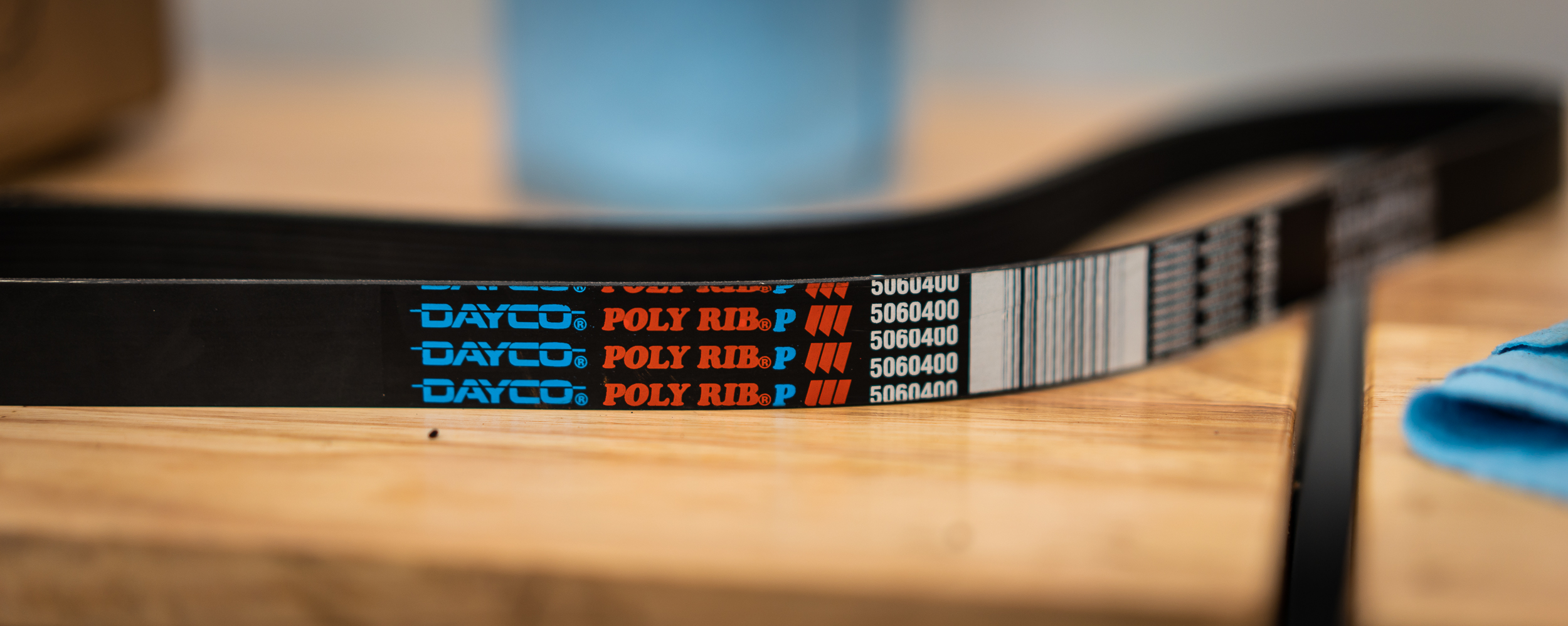
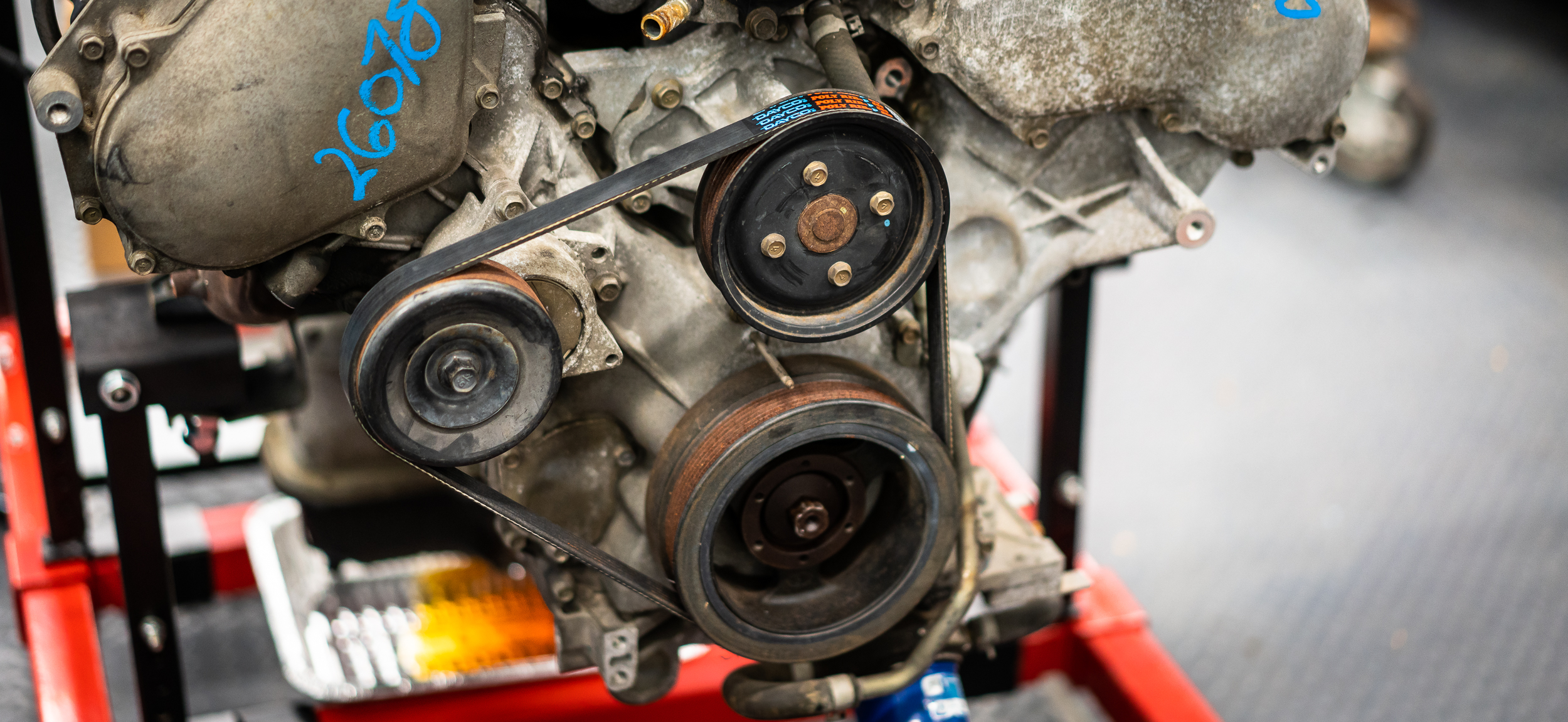
I found an appropriately sized serpentine belt for the new slim-and-trim (no) accessories configuration, so I put that on. Fits great. Yay.
I found the timing marks and I guess thought it was important to take a picture? Not sure, but here's that:
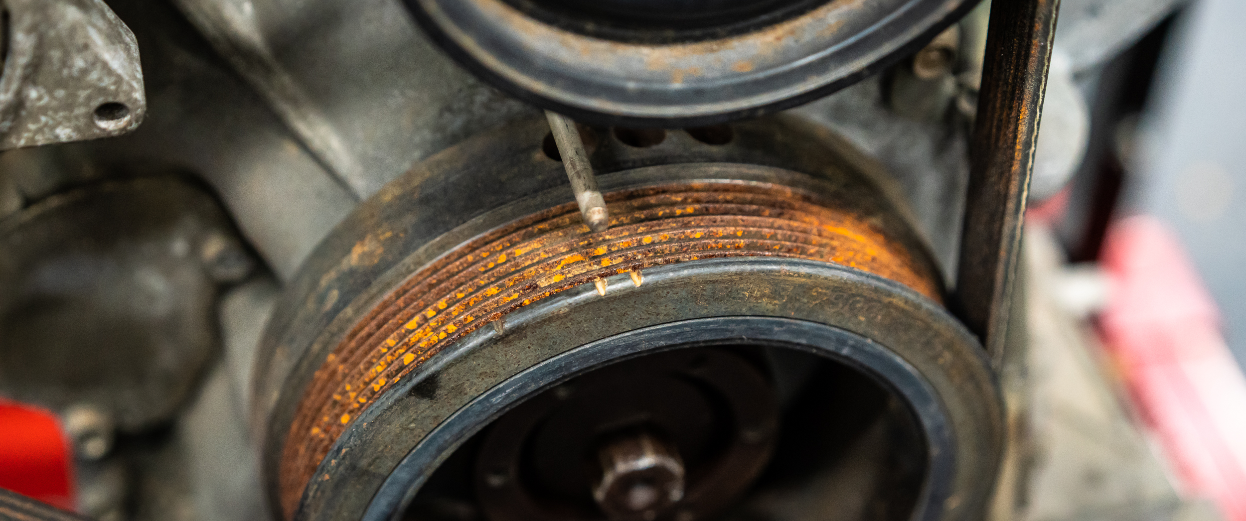
As I've noted before, I absolutely hate the pie-plate trigger wheel and cruise-ship VR sensor I've sourced for the crank angle, but it's a simple setup, so I'll use it for this initial bit. I hope that I'll be able to work with someone like ATI to get a lightweight damper that has the trigger pattern integrated into the damper itself, then use an OEM Bosch sensor that is readily available. I've heard Ford has a decent selection for this?
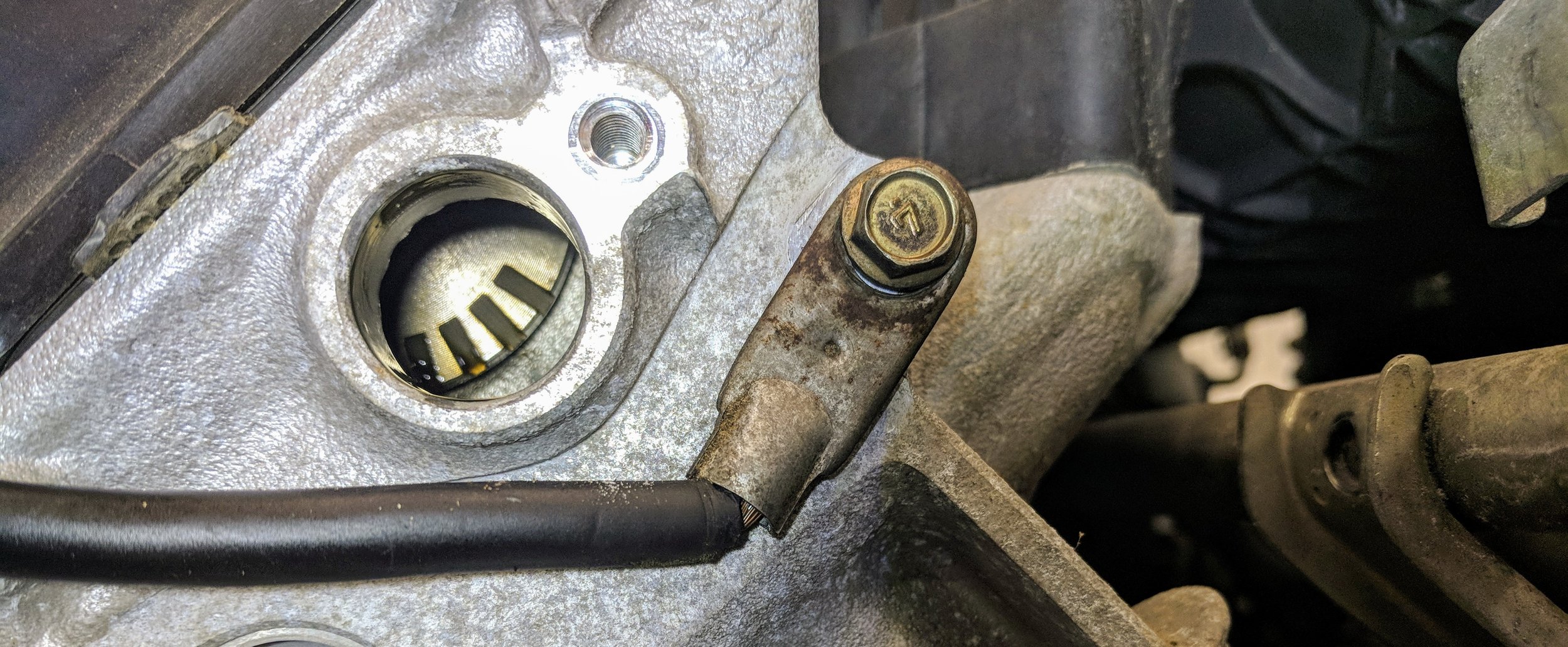
Anyhow, I found a couple of bolt holes in the region where I need the crank angle sensor, then set about fabricating a mount.
Here's the spot:
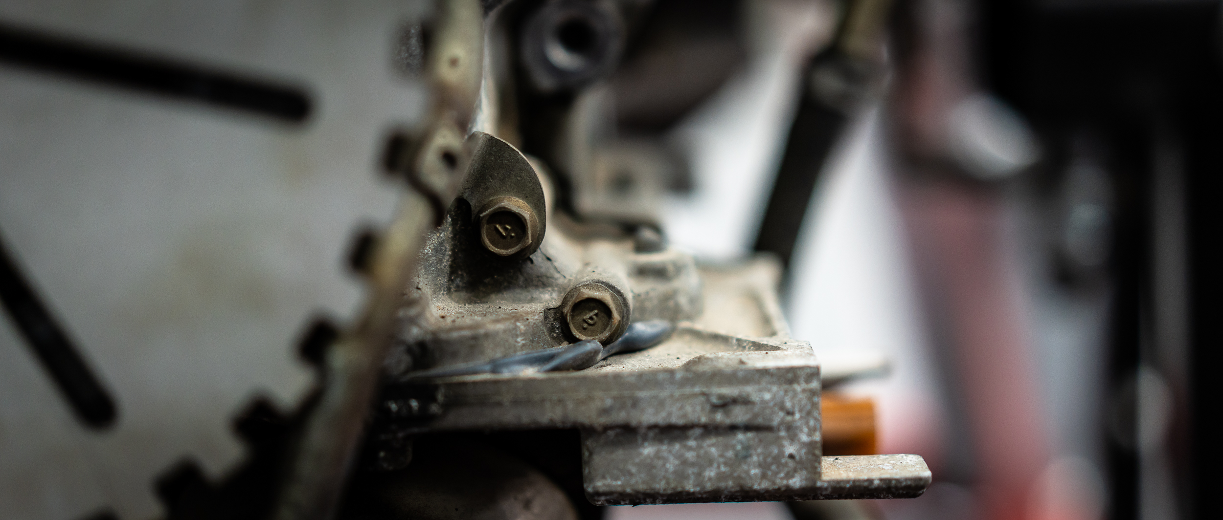
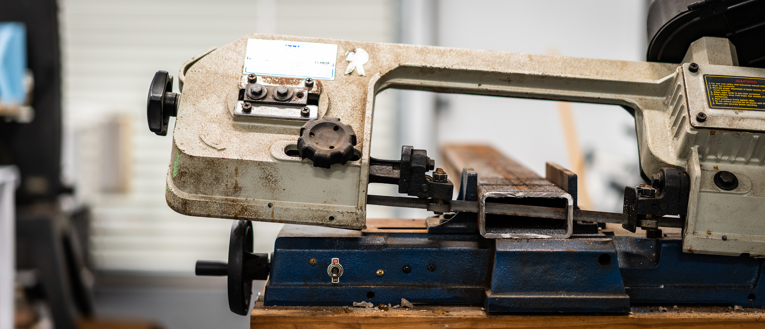
I bought a lot of extra 2" x 4" rectangular tubing when I made the test stand engine mounts, thinking it was a handy size that I might use in the future. The future is now and a slice of that would work well for the sensor mount.
Cutting with an angle grinder is not my absolute favorite, so a I dug a horizontal bandsaw out of Nik's pile of craigslist artifacts. It needed just a little bit of rehab, but we got it functioning. I think it might need a new blade; each of the cuts took like 5 minutes. But it's nice and quiet and required no work from me, so I call it a win.
A couple passes on the drill press/step drill/bench grinder setup and the whole mess bolted together just fine.
Good lord it's ugly.
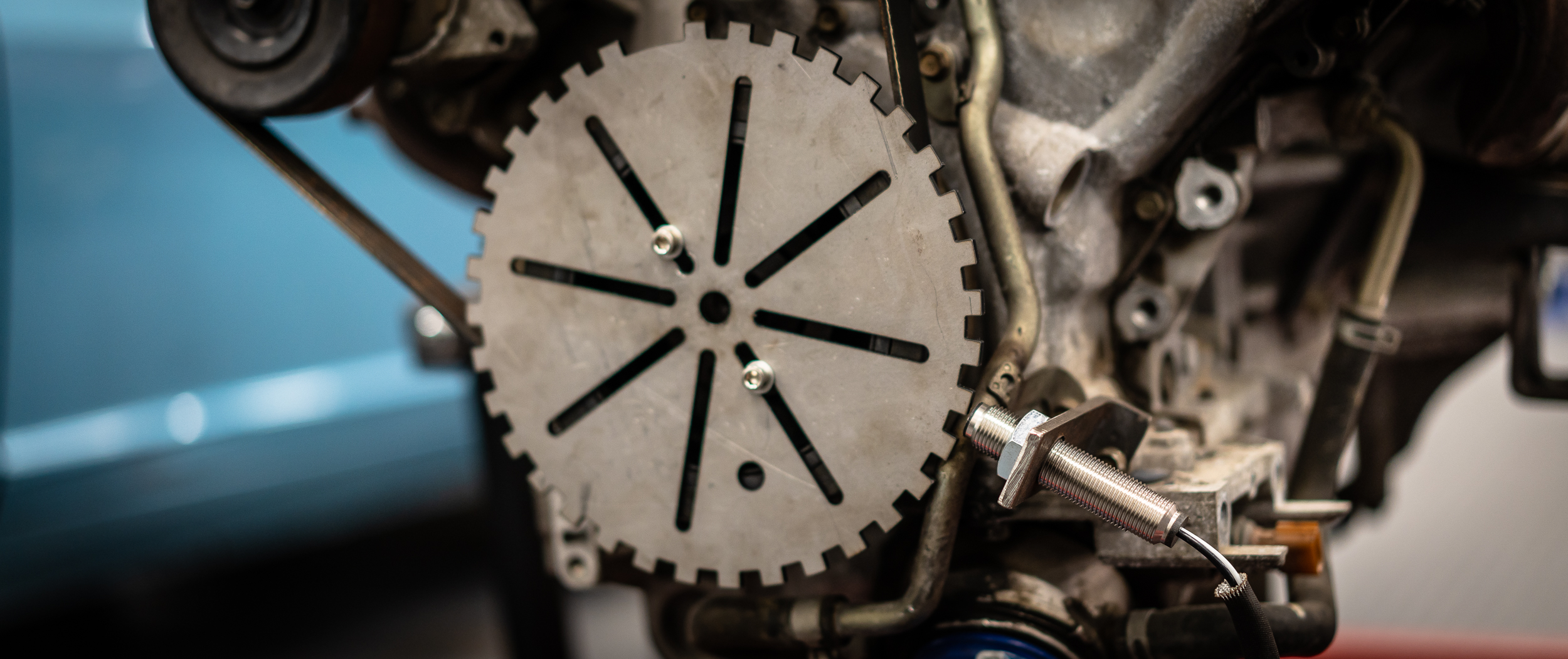
My next task with this setup will be to center the trigger wheel and add a third bolt to keep it from moving.
Not a particularly cohesive update here, sorry about that. It's just a bunch of odds and ends really, plus constructing the wiring harness, to get this thing started. We live in hope.
damen

Nice progress. One bite at a time and eventually the whole elephant will be gone.
Welp, the 280 is sending me hints.
It's mold.
Gross.
I cleaned it off and put some Damprid in the car. Hopefully that keeps the humidity level a bit lower inside the car? I'm open to ideas here.
Humidity sucks.

In reply to badwaytolive :
I keep one of those cheapie buffet style tins of cat litter in the RX-3. It's been pretty good for the last two years here in PA. It's a bit less humid here though.
I suspect you can do the same with just some desiccant. Looks like bulk is about $30 for 5lbs.

60w light bulb in a coffee can?
In reply to The0retical :
Exactly; I'm pretty sure that's what damprid is. I have some coming. Maybe I'll throw one of those cheap temp/humidity sensors in the car so I can see what's what.
In reply to java230 :
I think I get the idea here? Heat drying? Not sure that's enough heat; have you tried this to keep a car interior dry?
You'll need to log in to post.


