nocones
nocones UberDork
3/25/21 1:16 p.m.

In preparation for the suspension design I've been working on belcranks and spring rate math.  

It's not hard but also not easy.  Basically the plan was:

1. start with a target Frequency Front and Rear (~3.1 Hz, low Ground clearance, planning on Aero for track work)

2. Back out the required wheel rate based on estimated 40/60 weight, 1600lbs and 75lbs/corner unsprung.  

3. Calculate the overall motion ratio F/R required for my 500lb/in R1 shocks.

4.  Use geometry to figure out the distance the pullrods will move per 1" of wheel travel.  I converted this to an Average pullrod ratio.

5.  From that and the overall MR determine the target Belcranks ratio (length of shock arm to pullrod arm).

6. From target belcranks ratio determine functional lengths of the arms.  

Additionally because I just used the words Estimate a lot I'm planning on having massive adjustability in the wheel rates through variable belcrank positions.  The plan is to have 3 holes for the shock .75" apart from each other.  The Pullrod attachment will be slotted to allow the belcrank to be adjusted from around a 2.1-4.5 Hz ride frequency.   Obviously some of those frequencies would result in the shocks running out of travel, others would be so stiff there would basically be no travel.  But the important part would be that if the car is actually 35/65 or ends up 1800 lbs I can just adjust the belcranks rather then have to scramble to fabricate new ones.  I'll get into detail on how I'm going to control the slots when I build the belcranks (spoiler alert I already did it on the MG).

Before I get to far I will validate the Pullrod travel front and rear.  It's funny how radically different the belcrank ratios will be.  The fronts are ~1.0 and the rears are ~3.0.   Sin/Cos are agressive when you flop from 35/55 degrees.  

I can elaborate on any of this math if people are interested.  I will get into the angles of the pullrods and shocks relative to the belcrank pivot when i start fabricating them.  For determining the desired overall ratios they don't matter much yet.

Thinkkker
Thinkkker UltraDork
3/25/21 1:34 p.m.

I have a mental image of what you are making.  I wonder how close I am to what you do.

I am interested in seeing the maths, only because its been so long since I went through this stuff and calculating it out.  Also, I may be interested in stealing your spreadsheet if I can move on to new projects and finish what I have.....

Robbie (Forum Supporter)
Robbie (Forum Supporter) MegaDork
3/26/21 9:18 a.m.

yeah, bookmarking this post...

Rigante
Rigante New Reader
3/26/21 9:23 a.m.

well all your spring math went over my head, i can manage ratiios and stress, but I'm a bit lost on ride frequency. I understand frequency as a concept but how does it apply to the ride?

NOHOME
NOHOME MegaDork
3/26/21 10:38 a.m.

Suspension frequency is a great benchmark for establishing chassis motion. Easy to calculate IF you have the damping coefficient for the system nailed down. The problem is that without it, you are just guessing and the entire equation seems to fall apart. As far as I am aware, shocks are not sold with any kind of a spec sheet that would provide this data point. It would seen that a shock dyno would be required to do any accurate calculation. Or am I missing something?


Pete

nocones
nocones UberDork
3/26/21 10:40 a.m.

Ride Frequency (Sprung mass natural frequency) really is meaningless overall, however it can be used to represent specific attributes of the suspension system.  

What it is is the rate expressed in cycles per minute (cpm) or cycles per second (Hz) at which the sprung mass (The weight of car supported by 1 tire less the weight of the tires/wheels/hubs/brakes) would bounce up and down at infinitely.   Since a car is not 4 independent masses, and there are inherent frictional losses in the system a car will not actually bounce forever but whatever bouncing it does will be at the suspensions natural frequency.  

It is calculated for a vehicle by taking the effective spring rate at the wheel (Wheel Rate or WR) and dividing it by the Sprung Mass (SM).   Deriving the formula from the actual formula for spring natural frequency (1/2pi*sqrt(K/m), where K is the spring rate, m is mass suspended) results in the equation for use on a vehicle of

NF = 187.8*sqrt(WR/SM) in cpm or NF = 3.13*sqrt(WR/SM) in Hz.   For Hz we just divide by 60s to convert (1cycle/min X 1min/60seconds = 1 cycle / 60 seconds).  

The 187.8 is just the aggregate of all the constants that pop out of the sq-rt when you convert from lbf to lbm, consider gravitational constants, and do the 1/2pi math.  

Ok now we understand where natural frequency comes from but why do we care?  It is a single number that considers the spring rate, the motion ratio, and the corner weight of the vehicle and gives you an immediate idea of the stiffness of the suspension and the wheel travel you can expect to use.  Because it compares wheel rate to actual corner weight it applies across all vehicle types/suspension types/spring types.   So my pullrod bellcrank dual A-arm suspension on a 1500lb car could be directly compared to the beam axle air spring on a Semi truck.   

It also considers the motion ration inherently.  My MG midget has 875 lb/in front spring coils on a car that weighs 1600lbs.  If I tell you that with no other information you will think suspension is super stiff because that is nearly 2x the corner weight.  But the MR of the suspension make the ride frequency ~2.5, Stiff but not unbearable.   When you make suspension changes to the Motion Ratio, or spring rate you can use natural frequency to compare the changes.  If i want to keep the overall ride compliance roughly the same but am exploring several different spring options I can simply aim for the same natural frequency to solve it.

Because a car at rest is exposed to 1G of load (and ignoring pre-load on the springs, and things like tender springs and progressive or digressively wound springs) we can use natural frequency to directly determine the droop/sag of the suspension.    This is because the ratio of WR/SM if we are using spring rate in lbs/in and SM in lbs we are left with the ratio actually being inches of travel at 1G (Lbs/in x 1 / lbs = in).  So if we solve the natural frequency equation for SAG =  WR/SM = 3.13^2xNF^2.  I've plotted the relationship between natural frequency and SAG bellow.  Again spring preload and progressive suspension designs will impact the actual amount of SAG but for a idealized suspension this is how the relationship works. 

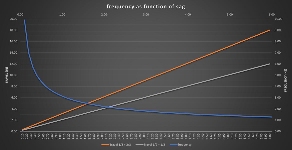
Also I've included the expected total travel for the 2 prevailing thoughts on the relationship between SAG and bump travel.  That's probably for another discusion but in my experience for linear suspensions designed to only use the bumpstops to protect the suspension from breakage on low CG vehicles total travel is 1/2 SAG, 1/2 bump travel.  Many people use 1/3 SAG, 2/3 Bump.  Things like the Miata have huge SAG values but relatively little travel before they get into the bumpstops.  Also many production cars will have large SAG but use progressively wound coils to stiffen the suspension as it travels.  So again this is just rough guides for understanding different suspensions. 

So why don't we just use the direct ratio WR/SM.  No idea, this makes us sound smarter and confuses people more which if we are honest is the goal of Engineering, because if people knew how much rounding and idealization Engineers used in deriving all the formulas we actual use to design stuff they would question us a lot more.  Also because when you get into damper design suspension frequency is an important part of identifying the amount of damping to target.  Damper design is a subject I don't have a lot of understanding on so someone else would have to elaborate on that, I just turn knobs indiscriminately until it feels nice.  

I'll make another post soon showing the math behind the spreadsheet, I suspect the big deal for most will be tackling the push/pull rod and bellcrank stuff, and the details of that are rough at this point.  I know the effective ratios I need, what I don't have yet is the angles I am targeting between the belcrank "arms" and the pullrods/shocks to give linear to progressive spring rates rather then digressive.  I will go into that with detail when I get to it.  I have what I need for now to build the suspension arms and pickup points.  I can give the spreadsheet to people who are interested but it's not a "clean" spreadsheet to use.  I developed it organically and illogically.   It's not like one of those online put your numbers in here and it vomits out pretty graphs and such.  

Rigante
Rigante New Reader
3/26/21 10:54 a.m.

thanks that helps a lot. 

nocones
nocones UberDork
3/26/21 11:11 a.m.

In reply to NOHOME :

You bring up a good point and you're probably right.  To do this "correctly" I probably should have shock dyno information matched to the springs I'm using.  I'm sure Hooke's law has a derivation that includes damping impacts on total system frequency.   Many aftermarket shocks do now include representative dyno charts, and if you tell them the springrates they will match the valving to the springs.  That said it's just not practical and in my experience necessary for me to get that information for my shocks.  It's very very easy to end up in paralysis by analysis with these things and continue to chase and optimize input until you never build something and you have to draw the line somewhere.  I draw the line at the tubes of mystery that I put inside my springs.  I'm counting on the fact that Yamaha did a decent enough job producing a matched spring/shock for the R1.  

15 years ago In FSAE we never considered the shock in determining spring rates for the car.  The shocks were considered after the springs where established (Less the inherent spring effect of using gas charged shocks).   Damping coefficients and adjustments where made to optimize system response, but that system response was based on the assumptions of the suspension as an Undamped sprung mass.  It's possible as technology has progressed particularly in load cells and the ability to cheaply make shock dynos that current thinking considers the spring/shock as a unit.  I'm sure that F1 and real pointy end racers do.  

I recognize that effective springrate includes the tire, any bushing compliance, any flex within the suspension components themselves, and the effect that the pressure charge on a gas filed shock has on the differential area on each side of the shock piston.   For analysis I'm ignoring most of those things also. 

I'm hoping most people realize that I am not trying to say this is the "right" or only way to do this.  I'm trying to communicate the way, and the why, of the decisions I am making.   I'm responsive to other ways to do things if they are effective and reasonable to do and always want to learn more.  That said I have 7 months to finish this thing so if the suspension is somewhat less then perfect that's ok.

Robbie (Forum Supporter)
Robbie (Forum Supporter) MegaDork
3/26/21 12:15 p.m.

I'm not sure you need the damper info if you use a factory matched setup. Ie, you're not changing the spring on the MC shock, you're just changing how far you move it. 

I'd hope that honda or suzuki or yamaha got the spring and the shock to match at least reasonably well. 

From a hip shot I'd also guess that 1/2 SAG is much better than 1/3 SAG, since I think few people realize it's much worse for a tire to leave the ground completely than to hit a good bumpstop. 

Robbie (Forum Supporter)
Robbie (Forum Supporter) MegaDork
3/26/21 12:19 p.m.

also RE sag. Carroll Smith in Tune to Win says that a racecar wheel should have 3 inches of bump travel and 3 inches of droop travel minimum. 

This is both in line with 1/2 sag, but also probably WAY more total travel than most people would expect for a racecar. 

gumby (Forum Supporter)
gumby (Forum Supporter) Dork
3/26/21 5:21 p.m.

Such maths, much wow. I read it all, and even understood a little, but I better just stick to welding....

nocones
nocones UberDork
3/27/21 12:33 a.m.

OMG GUYS THE CHASSIS IS SUPPORTING THE ENGINE AND TRANS!

Full levetation has been achieved (Ignore those little blocks of wood in the front, they are the jig that held the front of the subframe together and are what is currently keeping the chassis from teter/totering down). I cheated a bit and did not fit the inner plates on the trans mount.  I will do those after the subframe is removed when access can be much easier without the engine/trans in the way (The mount is removeable from the trans).  I ended up makeing a little K bar crossmember for under the transmission (12" of 3/4 tube, 10.5" of  1", .08 sq-ft of .125 plate).  4 more tubes and then it's on to suspension.

+2 Hrs, +$1.76.  Also Robbie stopped by this week as he was in the area.  Had a good time chatting with him and showing him around my general mess.  He's good people.  If anyone else is in the Champaign Il area and wants to see the car and maybe grind something let me know.  

nocones
nocones UberDork
3/27/21 6:28 p.m.

Quick midday update.  I had about 30 minutes to work so I cut and welded in the rear verticals and the reinforcement where the lower diagonal 3 will land.  The reinforcements are just 2-2" long pieces of a bedframe I grabbed off the side of the road.   I really should use more of it in the build but it's rare that angle iron has a good purpose on a racecar.  This was one of those moments.  Now just 2 tubes away from suspension!

Obviously there will be some triangulation added to the subframe when the subframe is removed for final welding.  

nocones
nocones UberDork
3/28/21 9:34 a.m.

So I got the rear subframe as finished as it will be.  Added the rear uprights pieces and the lower diagonal 3's. 

Then I procedded ed to attach the axles, uprights and lower ball joints to get ready for fabricating the A-arms. 

 I couldn't resist taking a "glamour" shot with the trunklid on.  The 2nd picture is me standing on a stool that is still 6" below the build table.  Like with the MG perspective plays a trick on you and makes this thing look huge on the build table but it will be LOW and Tiny on the ground.  

gumby (Forum Supporter)
gumby (Forum Supporter) Dork
3/28/21 10:37 a.m.
nocones said:

Epic. That is all.

preach (fs)
preach (fs) HalfDork
3/28/21 10:53 a.m.

Words here saying I have no words.

For a sec today my 2 favorite threads were together. This and ACs corvair.

I dream to be in this class someday.

AngryCorvair (Forum Supporter)
AngryCorvair (Forum Supporter) MegaDork
3/28/21 1:16 p.m.
preach (fs) said:

Words here saying I have no words.

For a sec today my 2 favorite threads were together. This and ACs corvair.

I dream to be in this class someday.

First, I am honored to be mentioned alongside nocones. This build is so much more radical than mine. And he does a good job 'splaining stuff.

Second, get up on that high-dive and jump. It will inspire you to learn to swim. I had never welded before I cut the Corvair unibody to make room for C4 suspension. Take a swig of "what's the worst that could happen?" and put that HF cutoff wheel to work!

DeadSkunk  (Warren)
DeadSkunk (Warren) UltimaDork
3/28/21 1:26 p.m.

In reply to preach (fs) :

I'm building a tube frame car and I've never built a car before. As Angry says "Get up on that high-dive and jump". You'll learn stuff as you go.

nocones
nocones UberDork
3/28/21 4:01 p.m.

In reply to preach (fs) :

Yeah, everyone of us had to do everything for the first time at some point.   I'm not sure I would suggest starting off with a build like this, or Angry's, or Gumby's but don't be afraid to pick up a welder (or whatever tool) and try new things.    Not really because it's that difficult, but because it is very easy to get Overwhelmed with the VOLUME of work required.  Even though I've done this a few time and knew what to expect you can still get lost under the weight of what is left to do.  As a beginner the pile would look more daunting.  If you can find someone in your area that is "more skilled" then you more then likely they would love to help mentor you to grow your own skills.  

nocones
nocones UberDork
3/28/21 4:05 p.m.

Thanks for the kind words everyone.  It's reasuring to hear that people are following along and that they are as excited by what is being built as I am.  

mke
mke Dork
3/28/21 5:43 p.m.
Rigante said:

 308 below


imagine the abuse from the peanut gallery if you proposed that 308 chassis as a new build on here  laugh

hey, hey, hey now......we all know  308 is torsionally challenged but that is no reason to tease it!  Plus there are pieces missing to make it look even worse!

I love this build!

NOHOME
NOHOME MegaDork
3/28/21 5:58 p.m.
AngryCorvair (Forum Supporter) said:
preach (fs) said:

Words here saying I have no words.

For a sec today my 2 favorite threads were together. This and ACs corvair.

I dream to be in this class someday.

First, I am honored to be mentioned alongside nocones. This build is so much more radical than mine. And he does a good job 'splaining stuff.

Second, get up on that high-dive and jump. It will inspire you to learn to swim. I had never welded before I cut the Corvair unibody to make room for C4 suspension. Take a swig of "what's the worst that could happen?" and put that HF cutoff wheel to work!

I heard the the same thing a hundred time when I was doing the Molvo. Seriously, the only way to swim in the deep end is to jump in. Skills will come as needed.

nocones
nocones UberDork
3/29/21 10:42 a.m.

Didn't get much done last night.  Only spent about 1 HR in the garage and made these little stands to hold the uprights in position.  I also spent some time doing the old Drink and Think staring at the uprights to plan out the upright adapter.   Tonight I'm going to turn my concept into cardboard.

Robbie (Forum Supporter)
Robbie (Forum Supporter) MegaDork
3/29/21 11:30 a.m.

I really thought I posted this but I don't see it now. the gist was:

I love the subaru for CG height. Such a perfect match for something like this. 

preach (fs)
preach (fs) HalfDork
3/29/21 11:51 a.m.
nocones said:

In reply to preach (fs) :

Yeah, everyone of us had to do everything for the first time at some point.   I'm not sure I would suggest starting off with a build like this, or Angry's, or Gumby's but don't be afraid to pick up a welder (or whatever tool) and try new things.    Not really because it's that difficult, but because it is very easy to get Overwhelmed with the VOLUME of work required.  Even though I've done this a few time and knew what to expect you can still get lost under the weight of what is left to do.  As a beginner the pile would look more daunting.  If you can find someone in your area that is "more skilled" then you more then likely they would love to help mentor you to grow your own skills.  

I have this Opel see...and a welder. And a dream. Just no time.

You'll need to log in to post.

Our Preferred Partners
iHAOa7ZLCszhoREHBJI3bXvi1943NHX9YQErGpN3j64nAyv9FmZXmXgi5m25YZ6L