Long overdue update: Scope Creep is a Real Problem Edition
Last we talked, I had just redrilled the front hubs to 4x100 on a friends mill. I laid out a potentially viable rear rocker configuration and set about to design rockers. Down the rabbit hole, I decided to recheck my suspension design and I'm not entirely sure it won't bind. Sure, it doesn't bind at the moment, but I have some crappy little sheet metal clevises (clevi? cleavage?) connecting the tension links to the knuckles that may mask binding. I'd envisioned machining them on my friends mill, even went so far as to design and analyze the clevis. Problem being: I'd like to learn how to use a mill on my time without spending late nights in a friends garage. If it binds, I may have to take a nuclear approach and just use the Miata subframe that's sitting behind the garage.
Which brings me here:
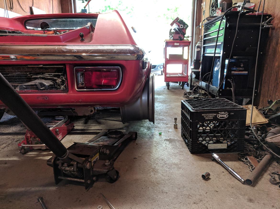
 Bolted the car back together, rolled outside so I can sneak this neglected puppy in:
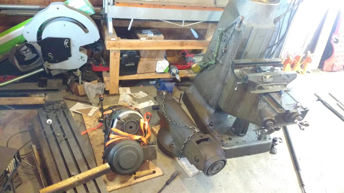
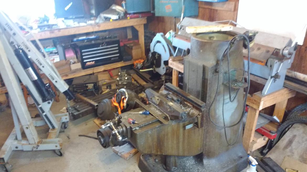
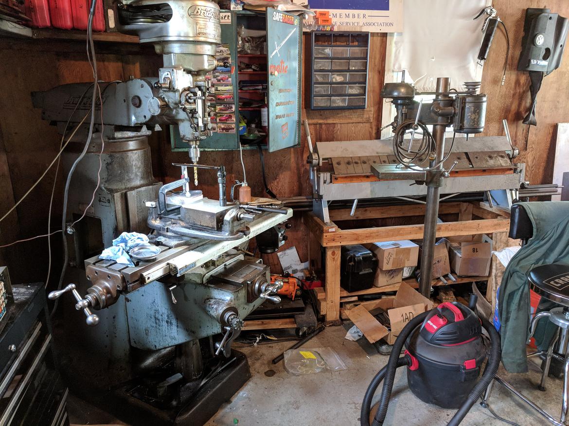
A filthy late 60's Bridgeport mill. Much of the next few weeks were spent taking it apart, cleaning, adjusting, lubing it up. Of course, now it needs a home in the shop, which means it's time to clean up 7 years worth of garage clutter and some general rearranging.
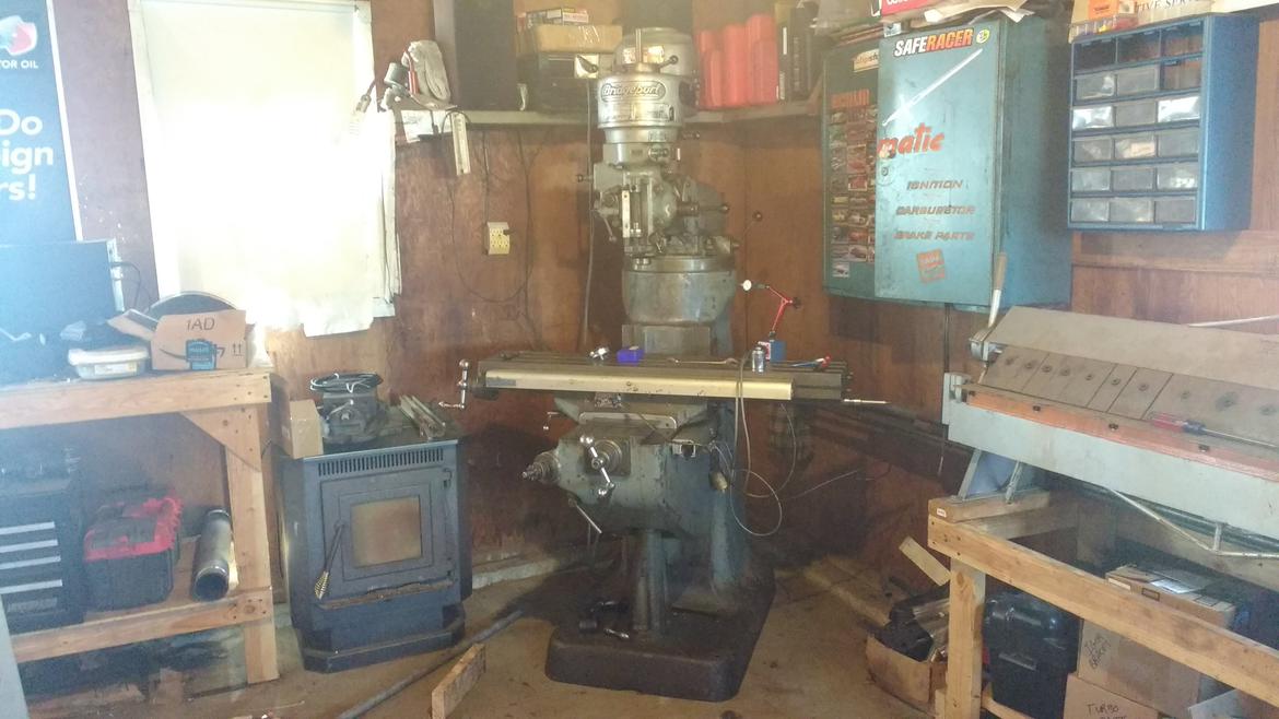
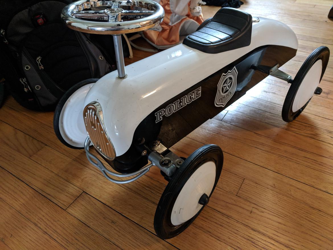
I've since moved the benches and pellet stove ~3' to the left. Now that it works, time to get back to Igor, right? Priorities... First, need to fix a toy for the kiddo. I picked up this little tow car last fall for $1 because it had a busted front spindle. What better project for making chips? All told, it took the mill, lathe and welder to get it choochin' again and wee lass loves it. Mission accomplished.
in reply to Brotus7:
in life, there are many levels of win. within this thread, you have crossed several of those levels.
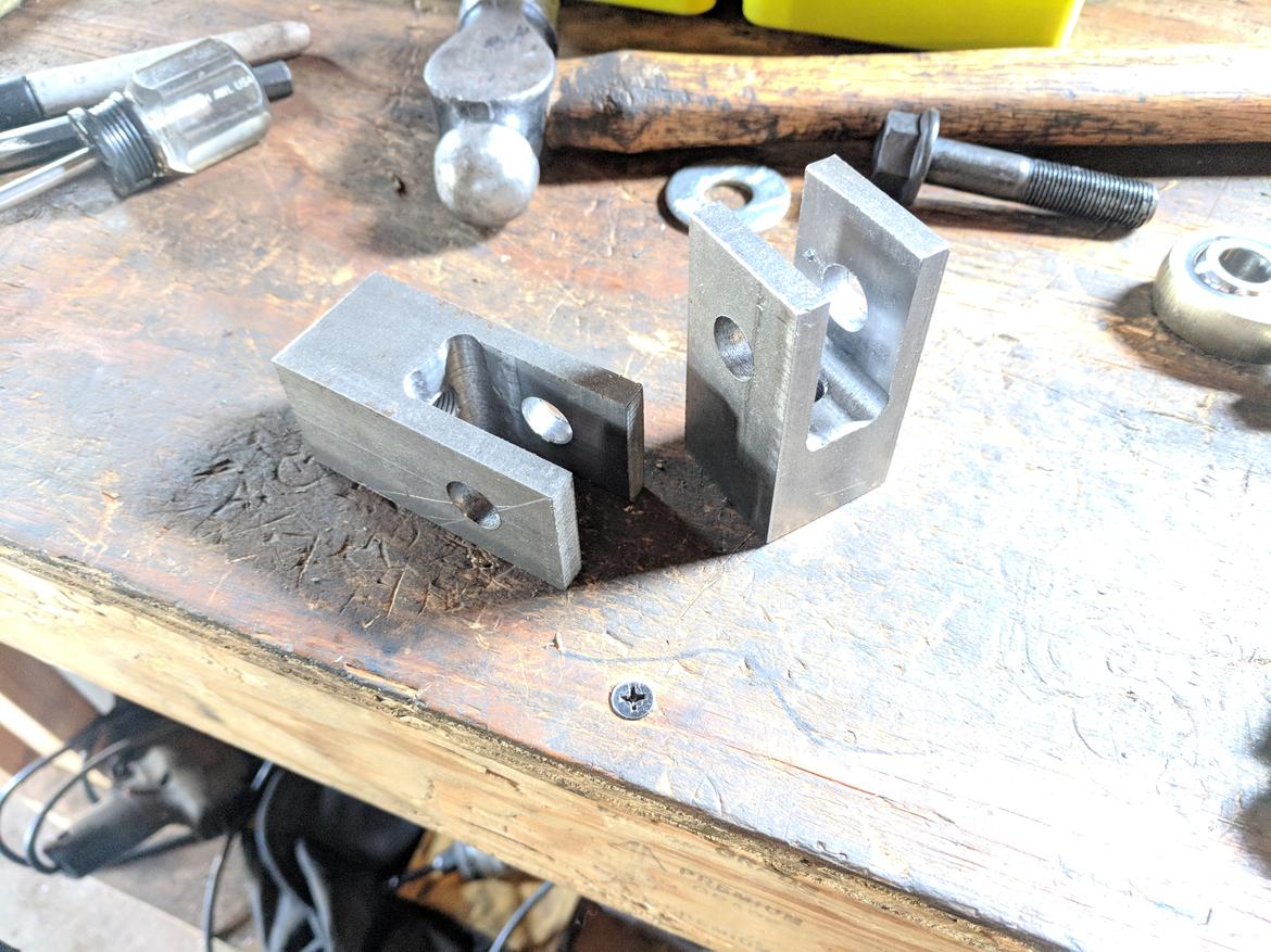
I've made a little progress lately. Learning a new skill is always fun, but certainly isn't fast. First car project on the mill was to machine up some brackets for the control arms.
Next: install and see if the suspension binds. So far, so good, next step was to machine up a couple conical spacers for the rod ends (no pics, sorry). Check travel again: no binding, checked bump steer: .015" toe changer per wheel, per inch of bump. My analysis showed that it ought to be a little better, but I designed in some tunability with the mount heights. More on this later.
Lastly, had to see what the 15x9s would look like.
Flares? I should track down some Miata fitment 15x7s and see how those pan out.
Flares are always a win, especially in a car so low....
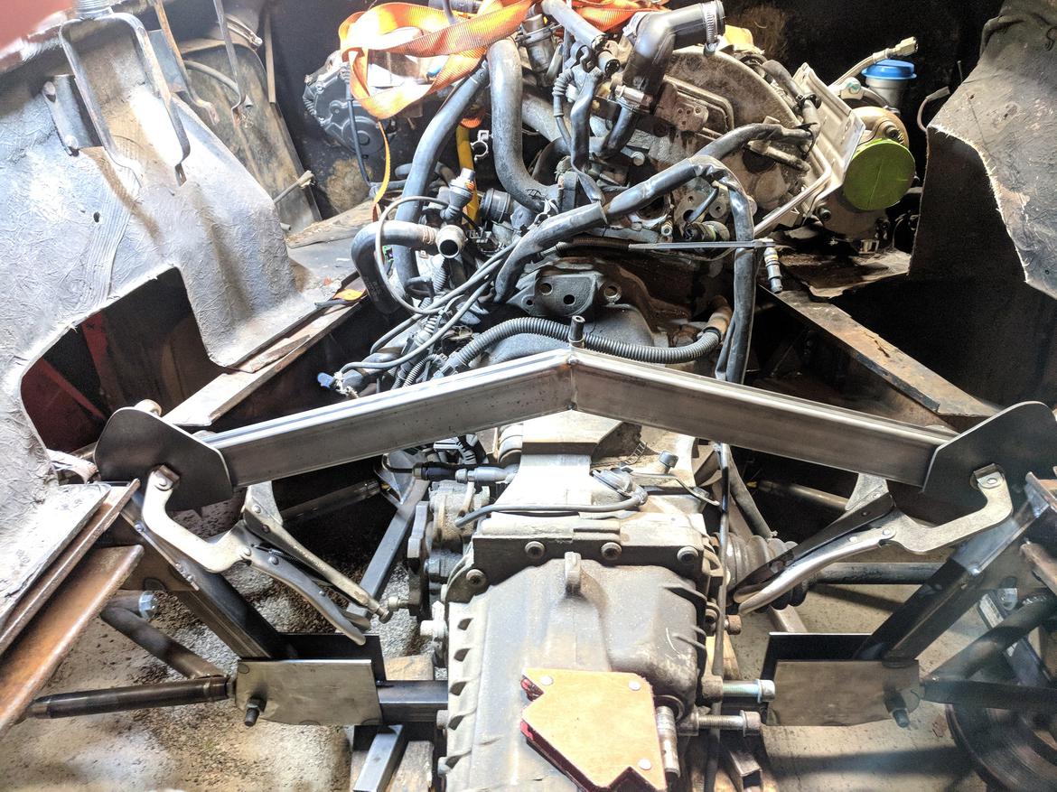
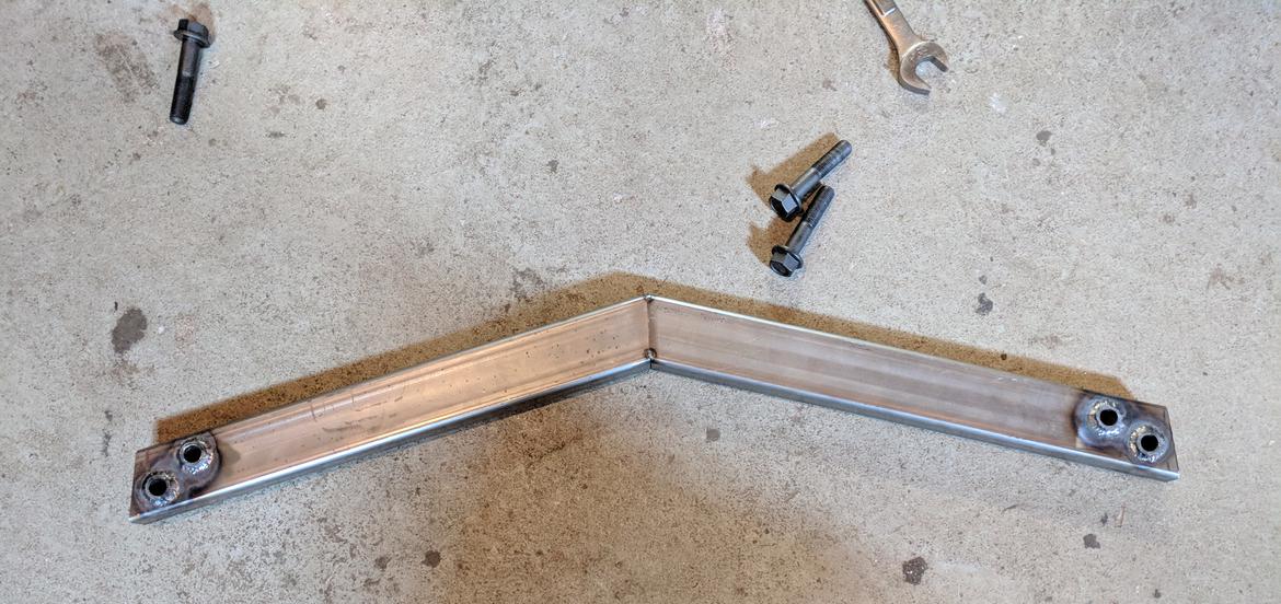
I'm back at it! Finally got the motivation to tack together the cross member that'll carry the rocker arms and coilovers.
Best part: it doesn't look like a complete afterthought.
Next up: need to cut the plates that'll get welded to the chassis in front of the cross member, then drill a couple holes so the cross member is removable, then time for rocker arm holes. Likely won't get that far this weekend.
In reply to Brotus7 :
Looking great! Some day I hope to attempt another Europa again.
Pete - Thanks!
Got some more time for some surgery on Igor - wrapping up the rear cross member. Started off by welding in spacer sleeves through the cross member mounting holes. It's been a while since I played around with the TIG and this reminded me that I'm a little out of practice.
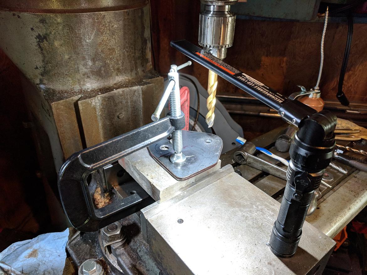
Next up: cut out 2 more plates and drill out the mount and rocker holes. I got a bit of a chuckle when stepping back and looking at what I did - I have a perfectly good drill press RIGHT THERE but not for the laziness of having to plug it in...
Shameless HF tool plug: the $20 LED lights are surprisingly good. Sure, real garage lighting is probably a worthwhile investment.
Installed. The plates are welded to the chassis on 1 side. I'll finish them when I pull the body off and wrap up the chassis - which may be one of the next couple steps?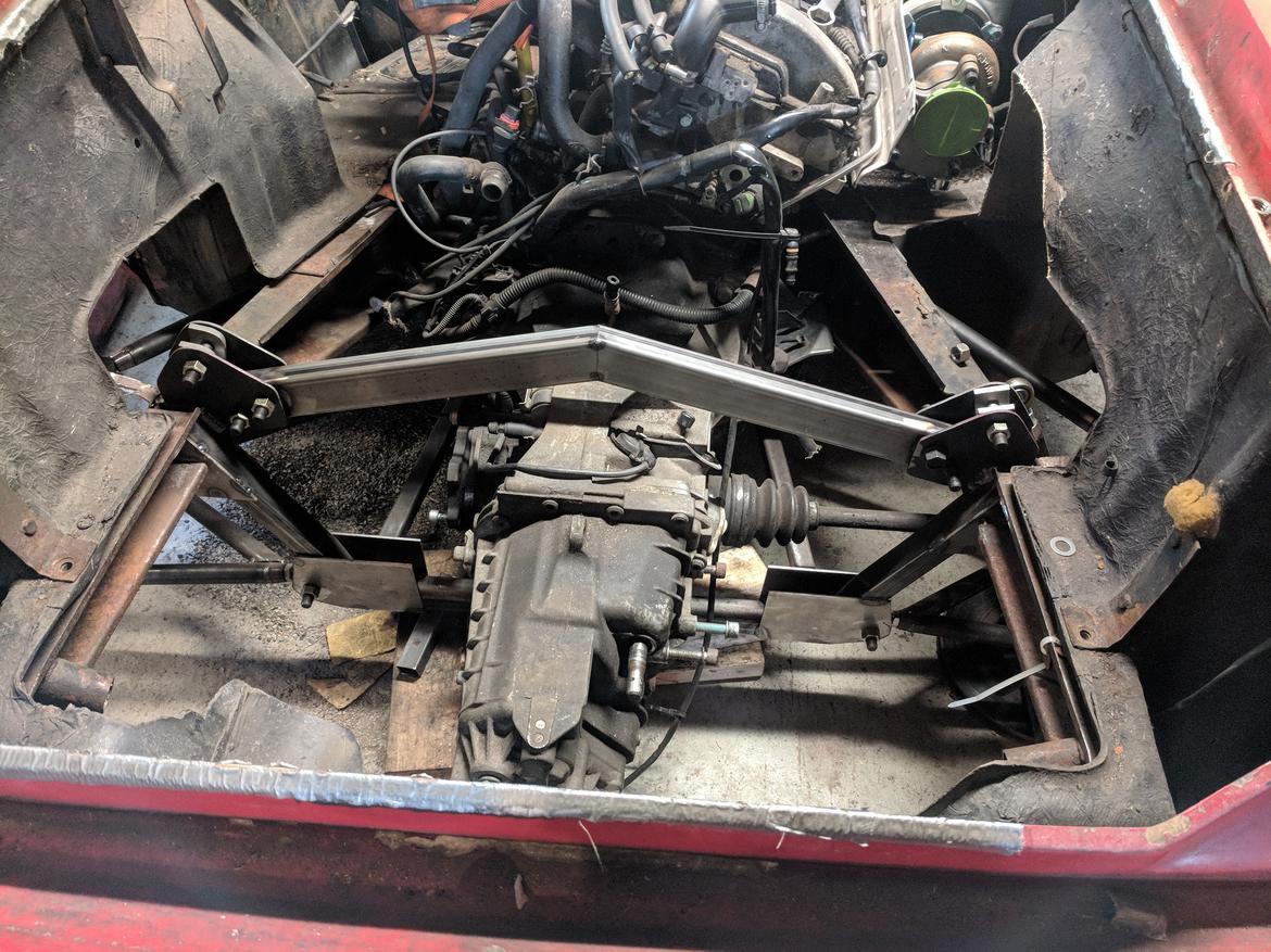
Next steps:
- Order up some aluminum for the rocker arms: complete
- Finish weld cross member
- Finalize coilover size/selection & finish designing rocker arms
- Machine rockers
- Turn car around and get back to work on the brake master setup
At that point, I think it's time to pull the body back off, drivetrain out and finish up the chassis welding/paint. I'll probably need to put in some chassis gussets for the roll cage so that I don't need to pull it apart again.
This is awesome. That is all.

NOHOME
UltimaDork
7/3/18 10:37 p.m.
I love seeing my Lotus fantasies played out while not having to live them!
Pete
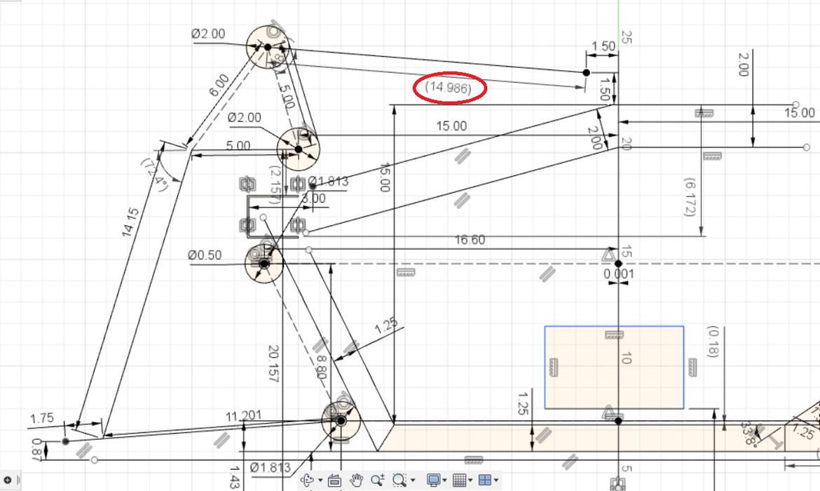
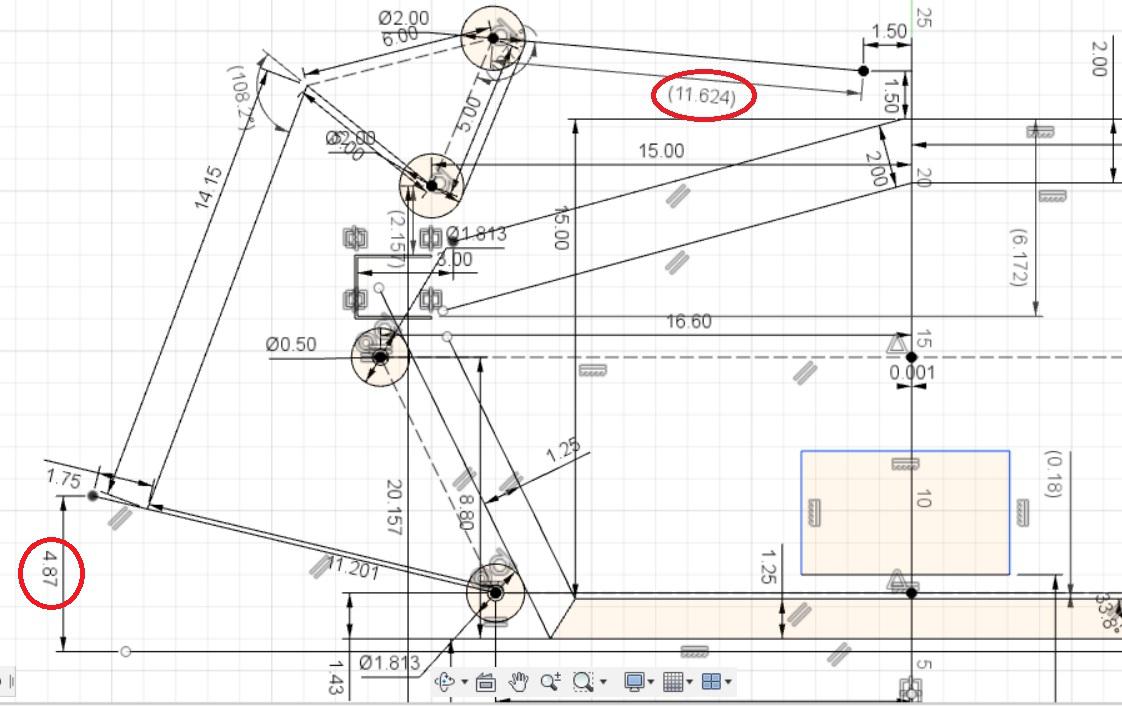
I spent a little more time designing up rockers yesterday. Looks like I can get ~ .84 motion ratio (.84" shock travel per 1" of bump) with a pretty constant ratio throughout the bump range. Shock length at ride height is just shy of 15" and min shock length at 4" bump is about 11.6". That said, I think 3" bump is good enough for an autocross toy.
Despite the extra clap trap, rockers have a few benefits. I like the idea of tuning the motion ratio to increase the shock speed (shocks tend to provide better damping control at higher speeds than lower, I guess that's probably at the expense of added heat generation...) and the ability to set ride height and shock spring height independently. That means when I finally get this thing going and realize the rear end looks like an altered drag car, I can shorten the push rod and not muck with too much else... to a point.
And for the nerd pics:
And at 4" bump
Also, just bought rear shocks - QA1 series 82s from Jegs. Since they won't ship until NEXT Friday, I have plenty of time to weld up the cross member and start looking at the brake master setup with fresh eyes.
-Andy
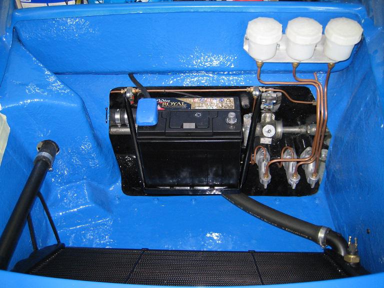
Not every idea is a good one, and sometimes it just takes starting to build it for you to realize. This time, it was the brake master cylinder setup. The stock Europa uses a funky bellcrank that you can see in page 2 of this thread. You'll even see the idea I wanted to mimic. What's different for me is that I'm also using a hydraulic clutch, which would mount on the front bulkhead.
Back to internet for wisdom. I think this is a better solution:
Combined with this. I'll have a rod that goes forward where the original clutch cable attached.
So, what's left to figure out? I'll draw it all up and see what it needs to look like. Ideally I can fit a brake bias adjuster onto the bias bar - just need to figure out how to snake it around the clutch rod.
It's been hard to get garage time this summer. I spent a few minutes earlier this week building a mock rocker arm from an old 2x8 board. Wasn't too happy with the product, but a few adjustments and another test piece later got me here: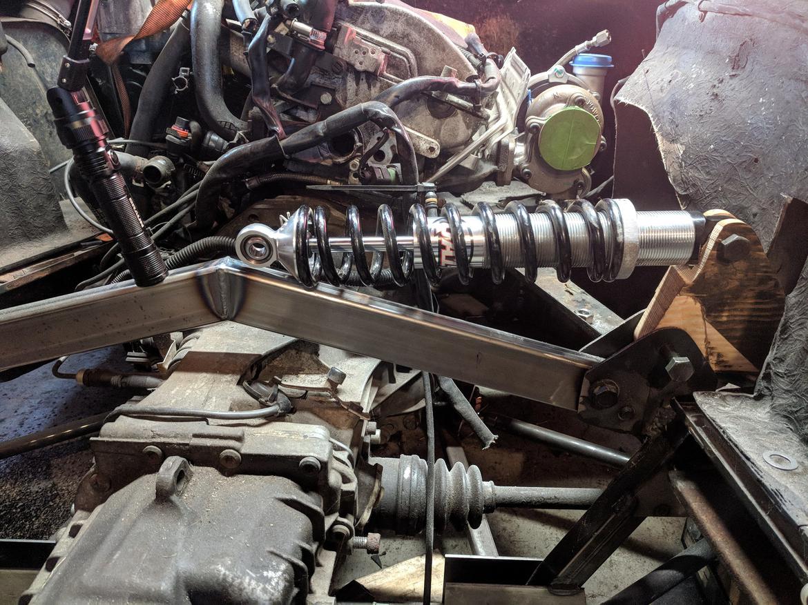
Pretty happy with how it came out. Namely, it doesn't look like an "oops." I'll need to figure out the clearance cut for the coilover onto the the rocker, then I should be able to build one from aluminum.
In reply to Brotus7 :
That looks like it will work nicely and provide a slightly rising-rate.
Thanks Pete.
It's been a while since I posted and it looks like I skipped the second attempt at the brake mount. Similar to the rocker, I opted to build a wooden mockup before I cut more metal.
The challenge with the master cylinders is that they have to fit under the steering rack, so some sort of spacer is required to gain clearance for the reservoir. The first concept would move everything out in front of the steering rack, but it seemed more complicated than necessary. I sketched up an idea and lobbed up a 2x4, only to find that the mount would need to be about 1/2" too tall to fit.
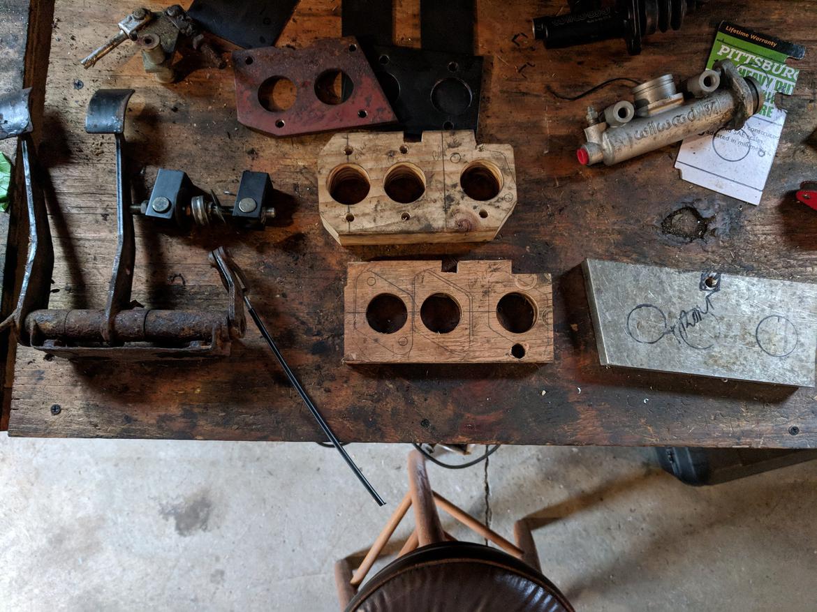
The top 2x4 is the failed second try, with the 3rd (and hopefully final?) concept shown just below it. If all goes well, I should have a little time tomorrow to finish it and see if it'll do the trick.
Brotus7
HalfDork
10/29/18 3:06 p.m.
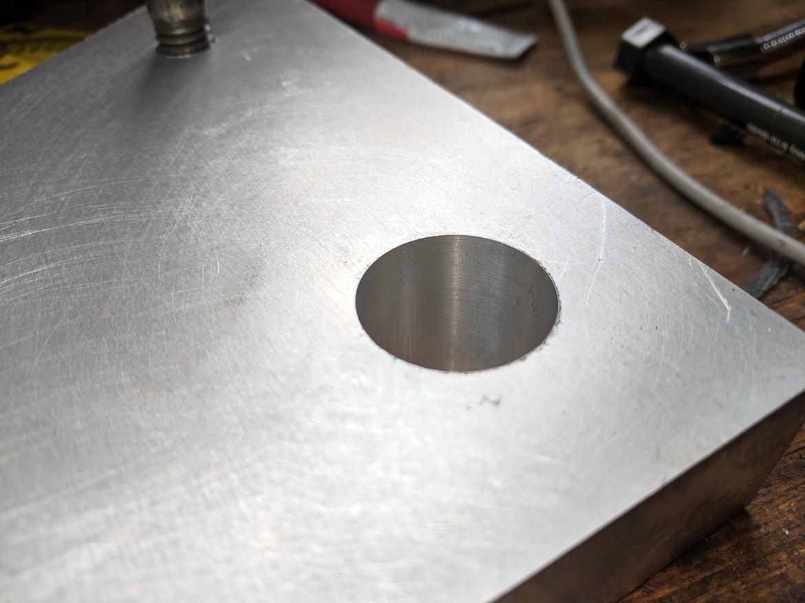
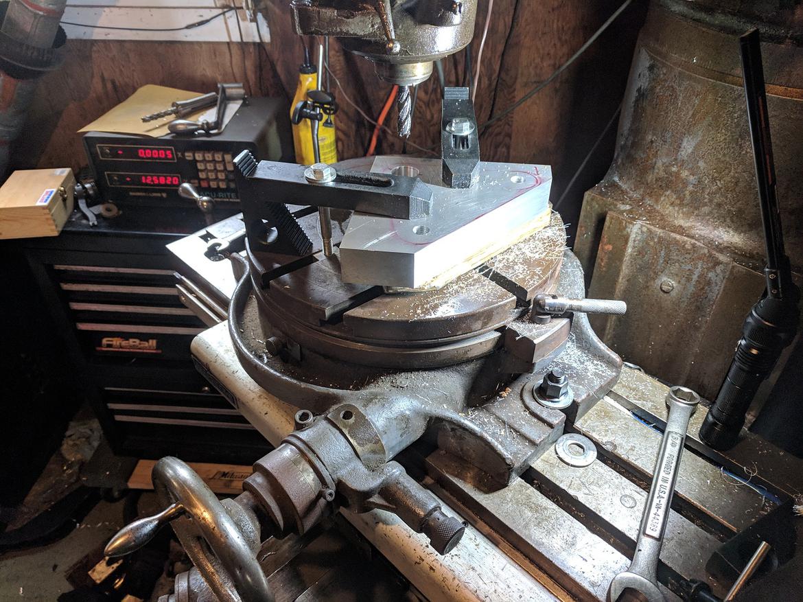
It's been 2.5 months, time for another update - slow progress. I liked the way the last master cylinder mount came out, so it was time to commit to making it from aluminum. Borrowed a buddies rotary table and set off (didn't have a boring head for the mill and accuracy isn't really required here):
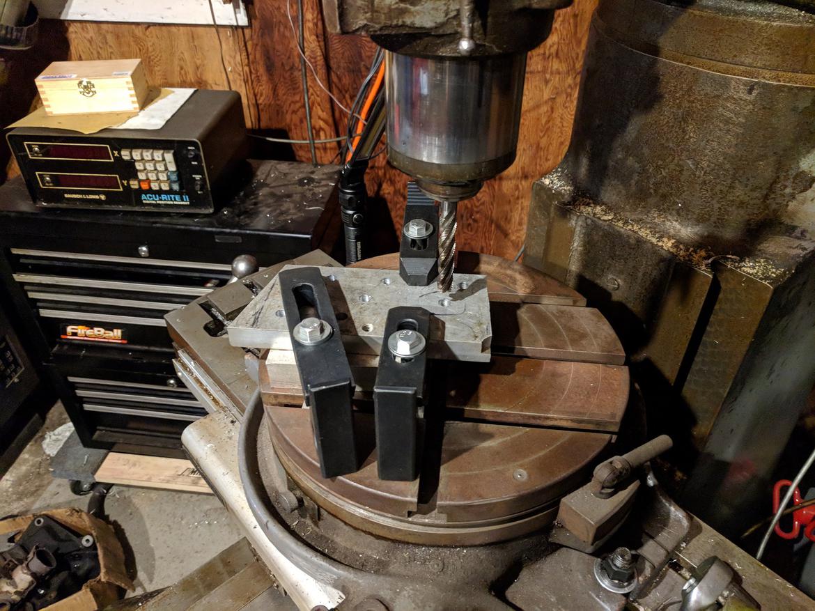
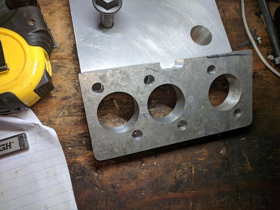
Lessons learned from that experiment: yes, it works. I can't hold a close diameter tolerance, and the holes are not super round since the plunge line is usually visible unless I sneak up on the diameter. I'll need to use a boring head to make the bearing bores in the rocker arms.
The rockers are made from 1.25" 6061 aluminum plate. Before wasting the expensive material, I taught myself how to bore a hole with reasonable accuracy on some scrap then set off to mill the rockers that upcoming weekend... Until I fell.
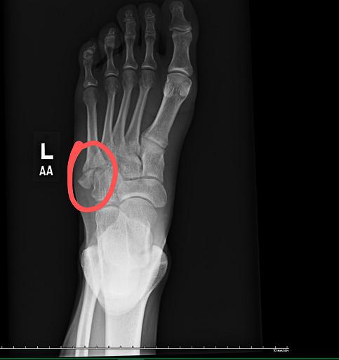
Yup, tripped on one of my daughters toys and broke my damned foot. Somehow I twisted and landed just right to break the 5th metatarsal. Dr's orders: here's a boot, wear it, don't do anything dumb and I'll see you in a month.
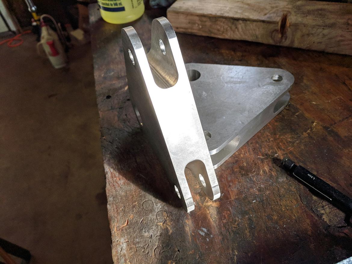
After a month in a walking boot, I got the go ahead to ease into shoes as comfort allowed. About a week later and I finally got some garage time. In my excitement, I didn't get any pictures of the boring head setup for the bearing holes. In any event, here's the following setup to start machining the outer profile of the rockers. I'm pretty happy with the tolerance I held with the boring head (.998-.999") for the two holes. but I'll probably need to touch the smaller one up with a hone to get a good fit on the bearing.
Also need to manually chamfer the holes to help the press fit.
Not sure how well this will work, but we'll see. I think I want to machine the 3 sides of the rocker, then reposition it on the rotary table to center on the pivot holes to put a nice radius on the ends. Then it's time to reinstall the vise and machine up the slots.
As much as I like the precision of doing work on the mill, it's certainly a lot slower than zapping steel together and drilling some holes.
https://www.aa-mfg.com/product/pedal-plate/
Might see what they have, already made. Nice having the entire paper catalog to flip thru to find stuff.

SkinnyG
UltraDork
10/29/18 7:00 p.m.
I broke my foot in exactly the same place, hopping out of the engine bay of a parked lowrider. Like a boss, aparently.
I can now tell when it is going to rain, two days before it's going to rain.
Brotus7
HalfDork
11/28/18 6:41 p.m.
It's been a month - time for an update.
Finished up machining up the rocker arms. All in all, I'm pretty happy with how they came out. There might not be quite enough clearance of the coilovers - we'll see once it's all together.
I didn't take pictures of the countersunk holes for the delrin thrust bushings, or machining the bushings up. Having never worked with plastics - it makes my small lathe feel like a manly machine  .
.
And - it's all together. Here's the car holding up its own weight!
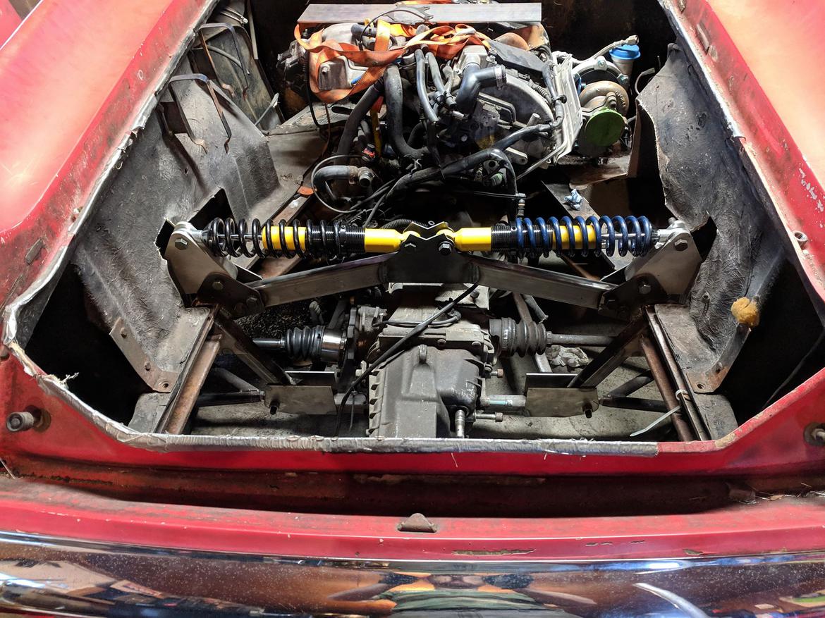
That's a satisfying view!
NOHOME
UltimaDork
11/28/18 8:01 p.m.
That is very cool! Rollers are a great feeling after an extended period on the stands.
Pete

nocones
UltraDork
11/28/18 8:38 p.m.
Yay more pushrod suspension action. Love this build. I didn't notice the mill addition. One is definitely in the plans for my garage.
Brotus7
HalfDork
11/28/18 9:52 p.m.
Thanks guys.
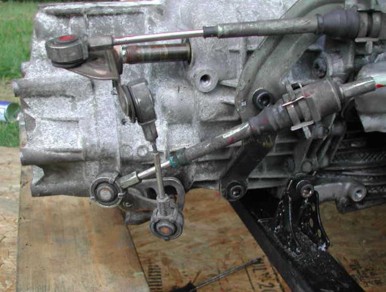
Just scored the shift linkage and cable bracket that mount to the transmission. Even if I need to modify it, just having something in hand helps move the project along. And it was cheap. 
Already have a MR2 spyder and Boxster shifters in hand. Neither fits inside the backbone tunnel, so I'll need to cobble something up.

While I button up the rear suspension, finish welding and making the necessary rod end spacers and such - I'm looking a couple steps ahead. I think I have a plan for the shifter, with bits showing up this week. Next up - what to do with the exhaust and intercooler.
It's going to be a track toy - so I need a decent sized IC with good airflow that doesn't get heat soaked from the exhaust. On my old 4AGZE mk1 MR2, I ran an air to water intercooler using a SVT Mustang front core, big Jabsco water pump, and an ebay/frozenboost intercooler. Worked fine for the street and autox - but heat soaked within a couple laps at the track. The fact the intake was just an air filter on the throttle body meant it was ingesting hot air, so I noticed removing the hood would get me a couple more laps before it was down on power.
I don't want to repeat that again, so, air to air intercooler? How do I get decent airflow thru the core in the back of the car, but without heat soaking the cooler from the muffler (which itself needs to live somewhere and be big enough to get me under the threshold of the noise police). I'll need to shield the shocks from the exhaust as well.
Options:
- Side mount intercooler, ala mk2 MR2. Requires a NACA duct on the passenger side of the motor. Would be the coolest air possible running into the intercooler, but I don't think the net airflow would be that much to begin with.
- Rear mount IC. Run it in front of the mesh just below the bumper. Run the exhaust out below it. Would need to duct in air from somewhere. I'd rather not put a big scoop in the hood. It's been done before - but I'm not sure how much airflow it'd get nor how efficient it is. The build in the picture below doesn't have inboard shocks - so my transverse muffler would likely be a good 5-6" aft from what he has.

- Air to water intercooler. Really throw all the medicine at it as possible. Thin, high frontal area air to water heat exchanger in the front, 1" ID aluminum tubes running to a big pump, running to a non-ebay IC core. It'd be less efficient than an air to air with good airflow, but I don't have that. It'd also be fairly expensive, heavy, complex, and I've had negative experience going down this road before.
Or, there's one other option... Do I really stick with boosted power? 250 whp would be more than enough to keep a smile on my face in a car that's under 1500lbs. Been looking at 3.6L VR6s, and the BEAMS thread on the front page got me thinking about BEAMS, 2ZZ, or.... K24.
Do I ditch the 1.8T, get a K24, keep it stock for now. Get another, build it as a 250hp NA road racing motor, and never worry about heat soak? Sure, there's that business of an adapter plate, new motor mounts, figuring out how to make the alternator fit with the chassis.
Decisions. Thoughts?