


This is awesome! Looking good man!

This is awesome! Looking good man!

Thanks Seth.
I spent quite some time working on the wiring portion of the build so I can share the rest of the project with everyone. I need to take some follow up photos on several portions of the build but it gets dark at around 4:45 p.m. during the winter season.
Wiring. I hate it. I had originally planned on doing all of the wiring duties myself. My delusions of grandeur had me thinking I was going to relocate the engine bay fuse box and make the engine bay look extra clean. But life is a busy thing and as LS Fest was rapidly approaching earlier this September, it became clear I was going to have to seek help if I expected to be able to shake the car down during our event. The fuse box was left in the factory location and the ECU, rather than nestle it behind the dash where the passenger airbag once resided, ended up finding it self installed in the passenger side floorboard.
There is a performance oriented wiring shop here in town, called RTR (Ready To Race) Wiring Solutions. The proprietor is Ryan Arterburn and a friend of his Derek Johnson from Modern Speed took on the task of making sure the Dominator EFI system was installed properly in conjunction with ensuring factory creature comforts like my power windows, locks, sunroof, etc would continue to function as before.
As referenced in my introductory post, I elected to use the Dominator EFI system as it is able to control DBW, and the ability to read two wideband O2 simultaneously, and a host of other functions (most of which I won't be showcasing as I'm not running water meth, NOS, or a turbo, not at the moment anyway...).
ECU itself:
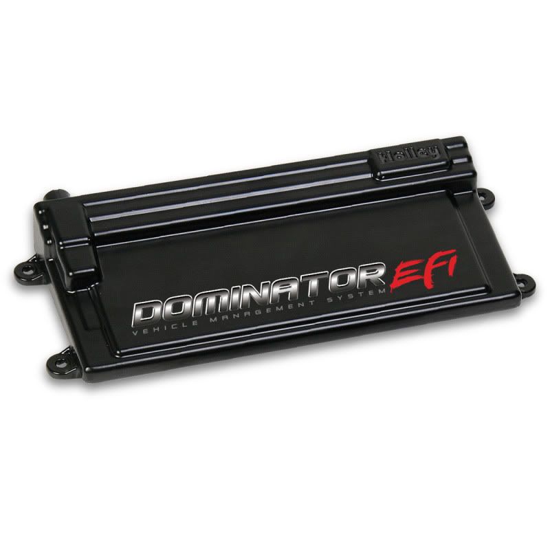
The ECU has a host of features and capabilities which I will share off the website for you here. I did not write this up, but I invite you all to read it through to see what this box is capable of for more than just GM LS applications. Dominator® EFI Vehicle Management Systems are intended for all engine applications, from street to unlimited high–end racing applications.
These systems have nearly unlimited capabilities to control any power adder, input, or output you can throw at them. Need to run a turbocharged, nitrous injected 8 cylinder running water–methanol injection? No problem with Dominator® EFI. How about control a 4L60E transmission as well as the fuel and spark on your street rod? No problem. There are also enough inputs and outputs to allow the Dominator® VMSs to serve as their own data acquisition and control module. The Dominator® EFI system eliminates the need for additional controllers as they are all contained in this one unit. The only thing limiting the Dominator® Vehicle Management System is your imagination!
Features:
-Twelve sequentially driven 8:2 peak and hold injector drivers, capable of driving up to 24 low or high impedance injectors as a standard feature. Multiple staged injector strategies
-Twelve channel distributorless Ignition (DIS) outputs capable of directly driving “Smart” ignition coils or Holley DIS coils. Will drive 2 wire coils with the addition of PN 554-112 high current coil driver module
-Plug and Play control of factory GM 24x and 58x LSx engines
-Integrated electronic transmission control. Controls GM 4L60E and 4L80E transmissions with more to come in the future
-Integrated dual channel wide band oxygen sensor controls. Works with Holley calibrated NTK or Bosch sensors. More channels can be added via CAN bus
-Integrated drive by wire throttle body control. Can control two drive by wire throttle bodies
-4 stage progressive nitrous control
-Turbo boost control
-Integrated water/methanol injection control
-Integrated “Data Acquisition and Control” allowed with massive amount of programmable inputs and outputs
-Internal data-logging standard with a huge 2GB of memory
-Self-tuning fuel table strategy greatly simplifies tuning process
-Store and change between four calibrations
-Individual cylinder fuel and spark control allows you to unlock your engine’s potential
-Optional 5.7” full-color touchscreen LCD allows easy on-the-fly tuning, data-logging or can be used as an easy to see graphical gauge panel
-Unique lb/hr based fueling strategy greatly simplifies and economizes tuning
-Advanced idle, closed loop, and enrichment strategies allow for very stable operation
-ECU is fully potted and can be mounted in the engine compartment or interior
-Sealed automotive and marine grade connectors
-Works with 4, 6, 8 and 10 cylinder engines
-Allows for use of common OEM sensors as well as customer sensor calibration input
-1-5 Bar MAP sensor capability
-Ignition Plug and Play with GM 24x and 58x LSx engines, GM HEI, Ford TFI, magnetic and hall effect trigger, and other ignition systems. New Plug and Play applications in process. Custom settings can be configured to allow many other applications.
-Two channel knock control sensor inputs for both one or two wire knock sensors
-Dedicated fuel and oil pressure inputs
-Controls both stepper and PWM Idle Air Control (IAC) motors
-Speed density, Alpha-N, or combination fueling strategies
-3 Rev Limiters
-Massive amount of inputs and outputs allow for limitless combination of options. Allows for unit to be used as a complete data acquisition system as well.
-13 - “Multi-Inputs” – Can be configured as a 0-5V sensor input, 0-20v sensor input, thermistor temperature input, or high or low voltage input
-30 - 0-5V Sensor Inputs – Configures any 0-5V sensor as well as some can be used as switched high or low inputs
-4 - Speed Inputs – Can be configured as a digital (square wave) input or an inductive input
-20 - 12v PWM Outputs – Can be configured as PWM or switched 12V outputs. Rated at 2A maximum
-16 - Ground PWM Outputs – Can be configured as PWM or switched ground outputs. Rated at 2A maximum
-All inputs and outputs are programmed using innovative new “Pin Mapping” strategy that allows inputs and outputs to be pinned as desired by the user, allowing for inputs and outputs to not be “wasted” by non-used dedicated functions.
-4 Stage nitrous oxide control
-Fully featured nitrous control eliminates the need for a separate nitrous controller device
-Can be configured “Wet” or “Dry” with closed loop feedback
-Progressive control based on time, RPM, or boost, requires part # 554-111
-Lean or rich safety cutoff
-Full timing retard/control configurability per stage based on RPM or time
-Integrated water/methanol injection control
-Uses Holley water/meth solenoids specially designed and calibrated for use with this EFI system to allow the user to enter water/meth flow as a percentage of fuel injector flow for water/meth tuning precision unmatched in the industry
-Nozzles available from 400 to 1000 cc/min
-Complete control of pump activation, and low system safety features
-Fully featured boost control capability eliminates the need for a separate boost control device
-Can be configured to control boost based on time, gear, speed, and manual inputs
-Gear based boost control configurable by several different methods
-“Boost Builder” functions offer the ability to assist building boost on the starting line by altering ignition timing, fueling, as well as nitrous oxide activation. Also can be used as an anti-lag function
-User configurable input and output programming
-Outputs can be programmed as pulse width modulated or switched.
-Unique circuitry allows inputs to be programmed as speed/frequency, 0-5V, 0-20V, thermistor, or switched high or low
-User configurable inputs and outputs can be programmed to have a variety of different inter-dependencies
-Configurable for: dual cooling fans, dual fuel pumps, AC inputs, basic TCC lockup, and multiple timing retard inputs
-User programmable caution and warning outputs for all sensors. -ECU Weight:6.480 lb.
That sums up the features of the Dominator unit. Other EFI parts I ordered to support the Dominator EFI unit:
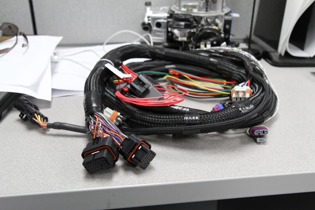
Main LS2 Harness:
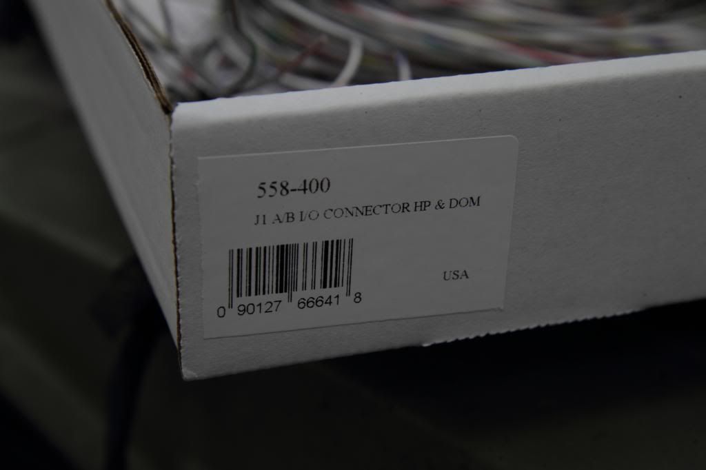
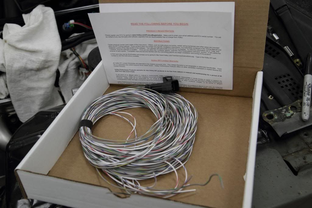
J1A/B Auxilary Connection Harness-http://www.holley.com/558-400.asp- aThis harness comes with four outputs and four inputs, but we wired the fans together so they only took up one output to trigger the relay connected to both fans.
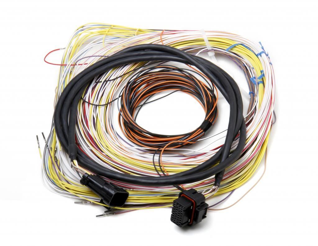
J2A Auxilary Harness- http://www.holley.com/558-401.asp- Auxilary Input that was pre-terminated for my secondary wideband.
553-103- 5.7'' touchscreen, allowing the user to control all data-logging and tuning functions on the fly with no laptop after intial setup. Also provides user with a graphical gauge panel displaying vital engine information.
Moving away from the ECU features, we'll get started on the installation of the unit on the car.
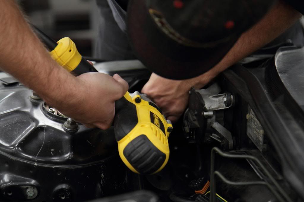
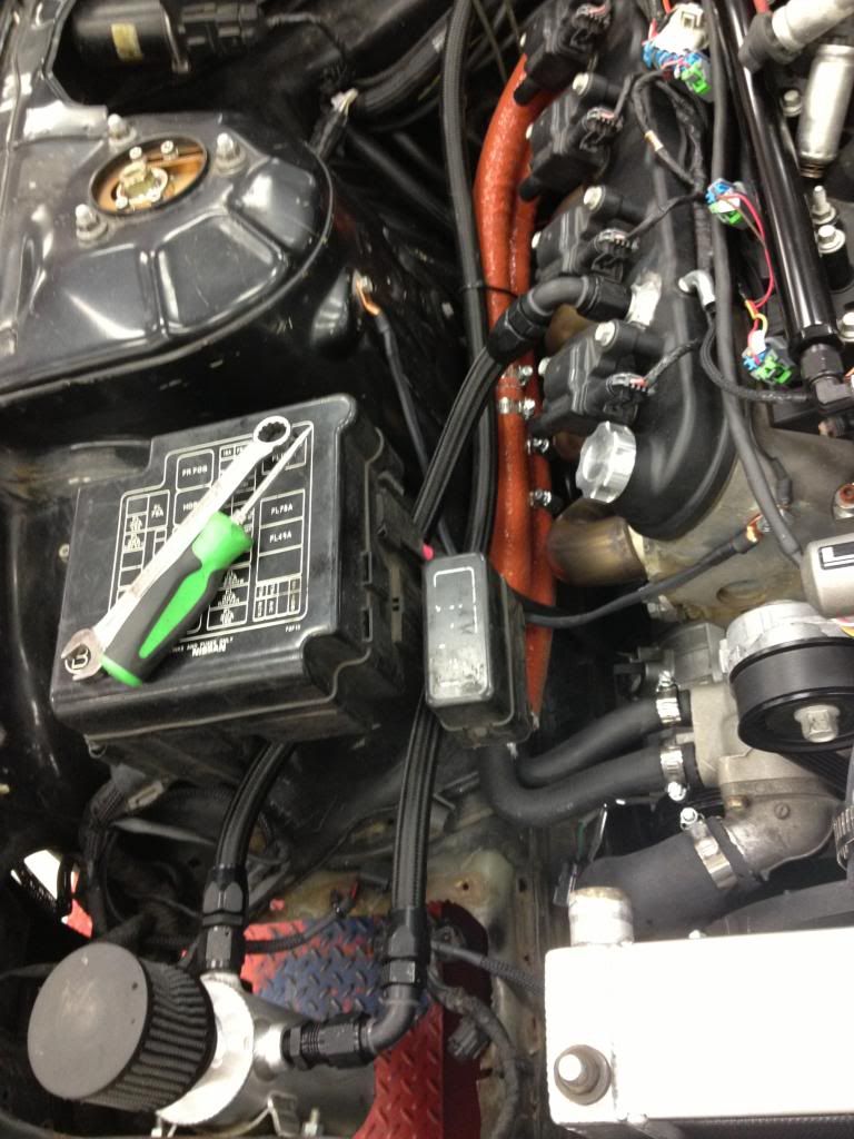
Drilling for Fan relay install:
Relays in place:
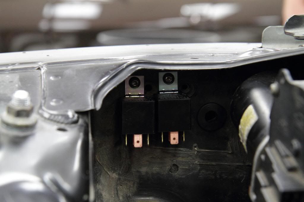
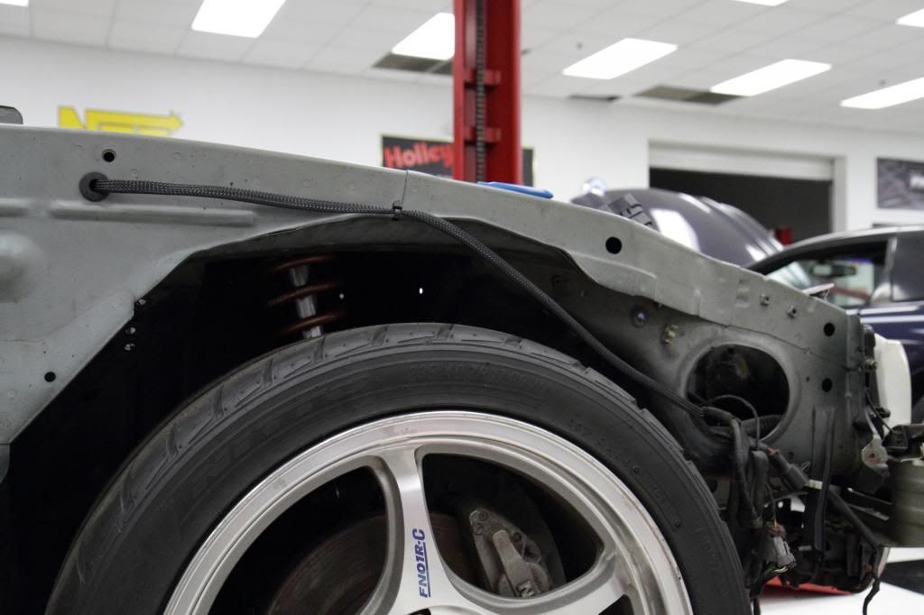
Relay wiring goes outside the engine bay and back in closer to the fuse box:
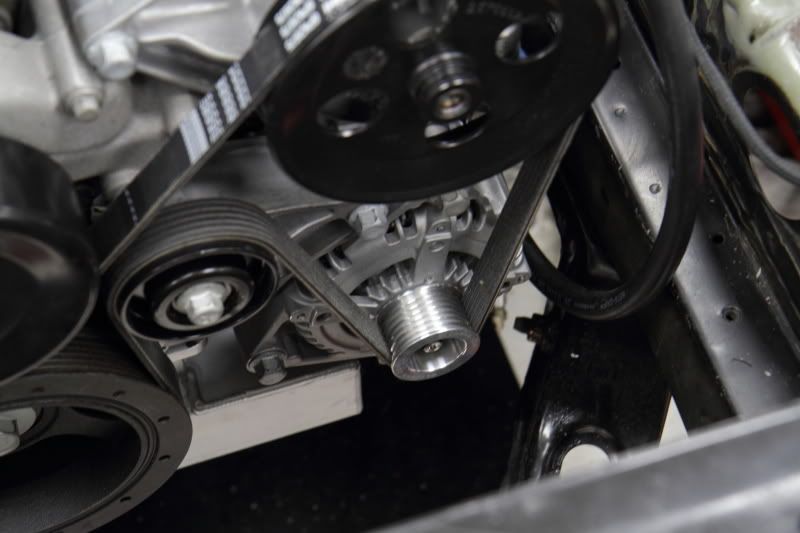
The factory alternator that I used (from the CTS-V) is computer controlled. I sent it off to Mechman.com to get that internal regulator changed to a standard non computer controlled type. The original CTS-V computer controlled regulator cannot be "excited" or "turned on" from an ignition switched +12V wire, so we needed to circumvent that.
• When the key is on and the car is not running, a resistor or a “no charge” indicator light is required to prevent a short circuit. Typically this circuit would have a light bulb in line, but in case you do not in yours, the resistor in Holley’s alternator plug/pigtail part number 197-400 will cover the function of the bulb.
He also installed a Mechman billet aluminum pulley on the front of the alternator which added to the cool factor.
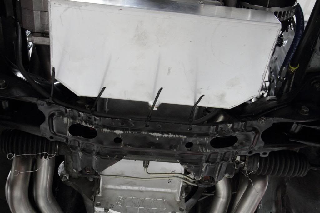
I believe the factory alternator wire ran from across the bottom of the subframe and that is what we did to get across the engine bay on this build also.
We came right off of the ignition switch and went directly to the ECU to control switch 12V power for the ECU.
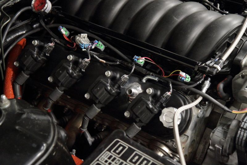
On the F3 plug we removed several functions of the wiring harness according to twistedsymphony’s website.
The Holley harness requires you to hook up very few wires in the grand scheme of things to get the engine to start up.
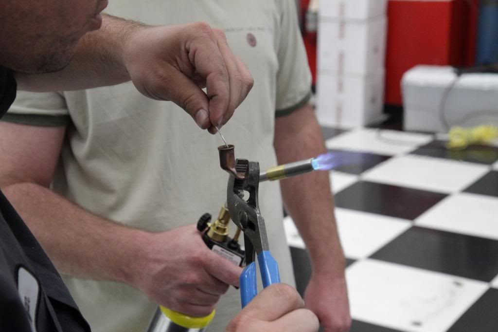
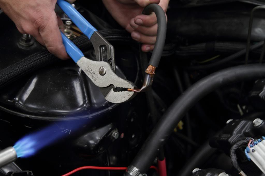
Black wire-must be grounded to the head or block Red wire- postive power came up through the passenger side of the cabin and through firewall and attached to distribution block on side of the factory fuse panel. here Derek and Ryan are heating up the terminal and melting the solder before inserting the welding wire I used for battery cable.
Getting ready to put the two together:
 Red wire of Main harness went directly to the battery.
Yellow wire of main harness was relocated from P1A1 to A28 to allow me to run an aftermarket tach 12V square wave signal.
Red wire of Main harness went directly to the battery.
Yellow wire of main harness was relocated from P1A1 to A28 to allow me to run an aftermarket tach 12V square wave signal.
Negative battery power we hooked to the bottom of the chassis in between the frame and the tow hook.
Green wire- Fuel pump wire. came off of the Holley harness to trigger the factory fuel pump relay. This allowed the ECU to send 12V to the relay and then the relay would trigger the pump. Red/white, was ignition switch that went right to the column.
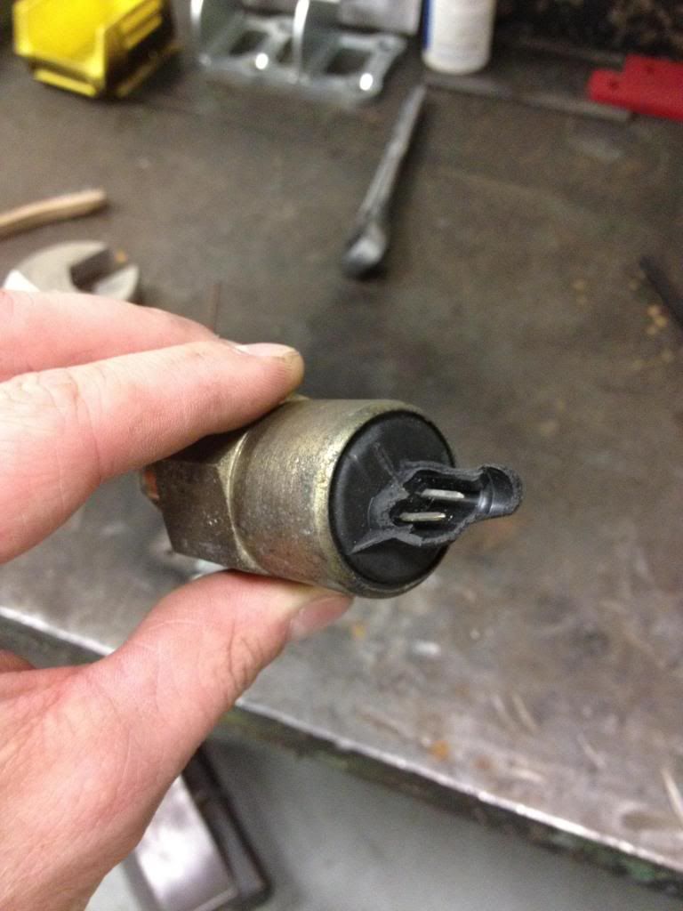
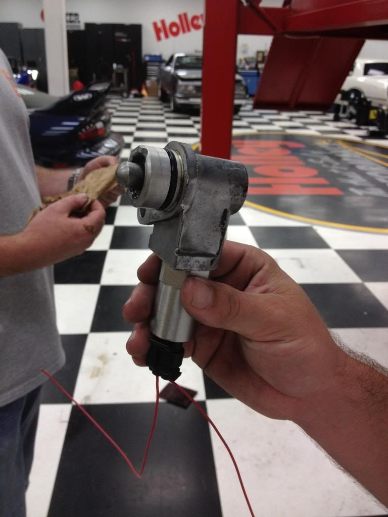
After sorting out wiring up the ECU we moved on to the reverse lockout solenoid. NOTE: You shouldn't have to do anything but hook this up normally, but mine was broken. Two years ago I drove our LS3 El Camino on Power Tour and it's brake pedal was setup to trigger the reverse lockout when it was depressed. Without this it seemed impossible to get the car in reverse. That being said I followed suit with mine. The connector on my reverse lockout solenoid was busted so I had to go to the local dealership and replace it.
Broken portion I replaced:
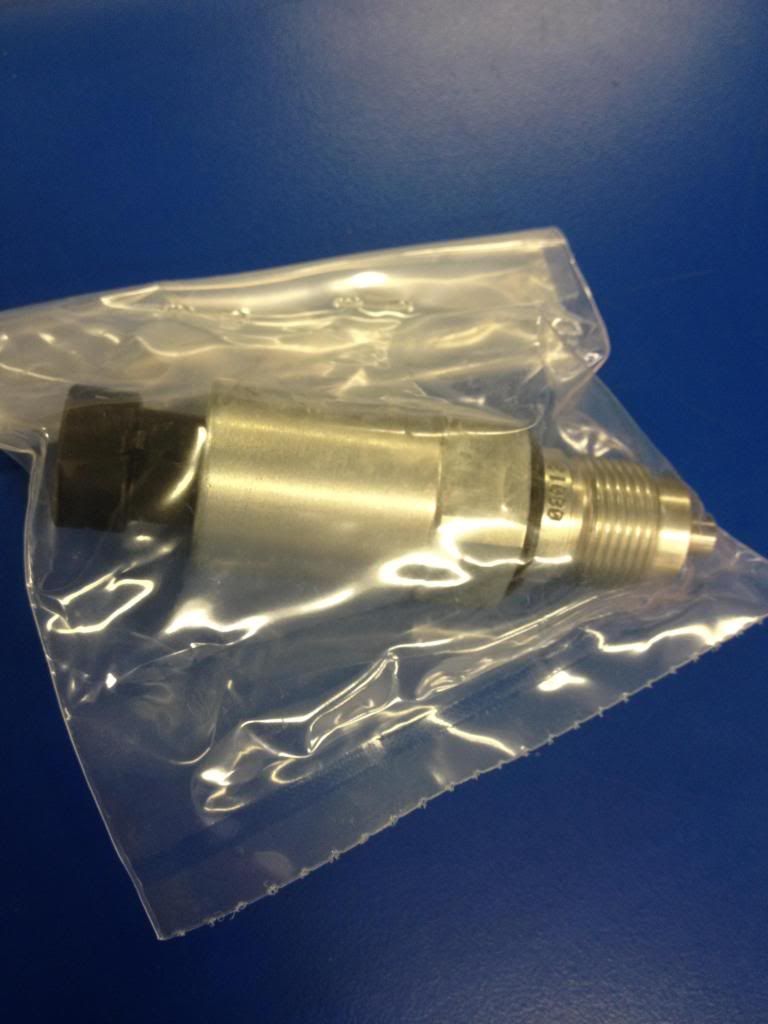
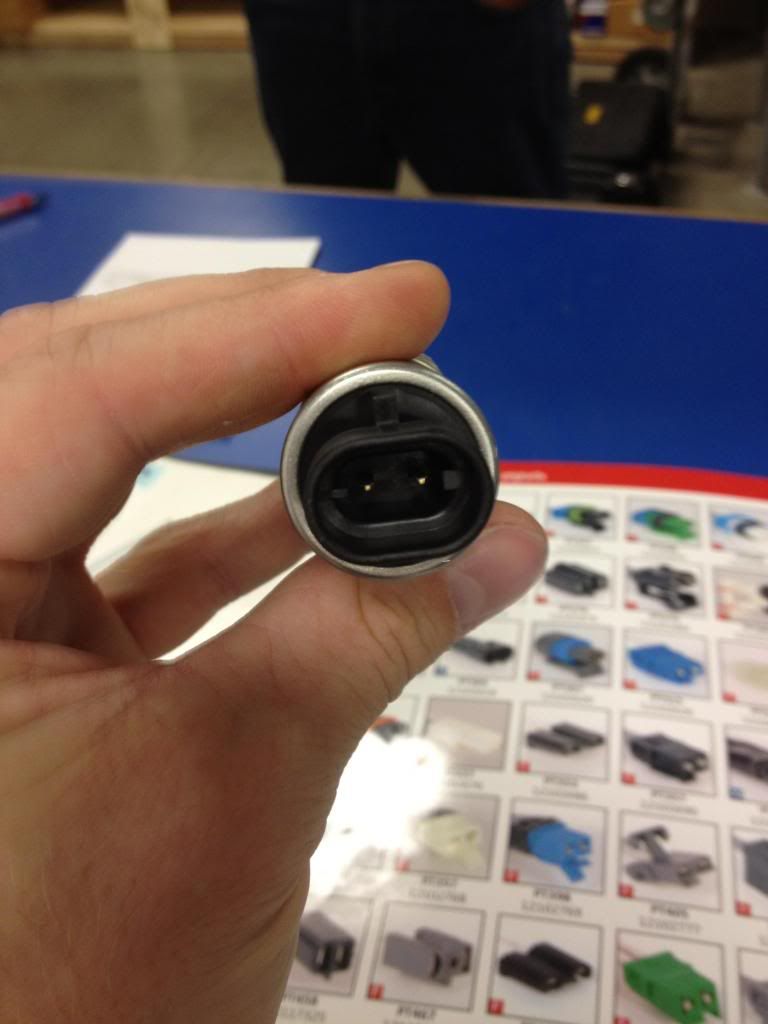
New replacement part:
 Separated housing in vice:
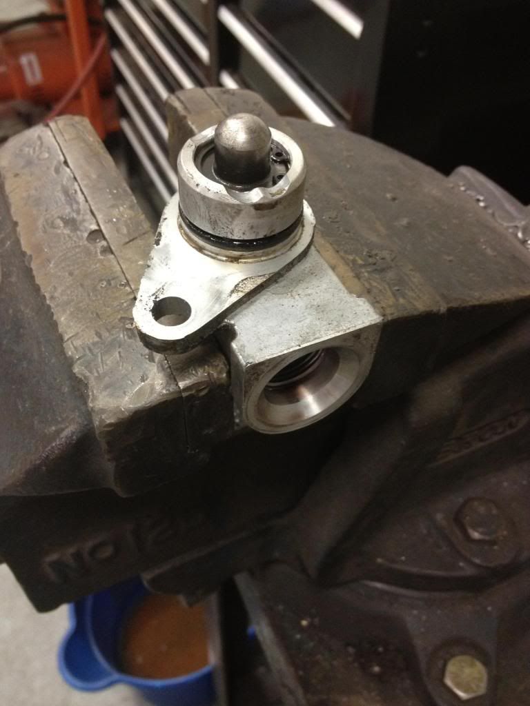
New solenoid ready for installation in housing:
Ready to go back on the side of the trans:
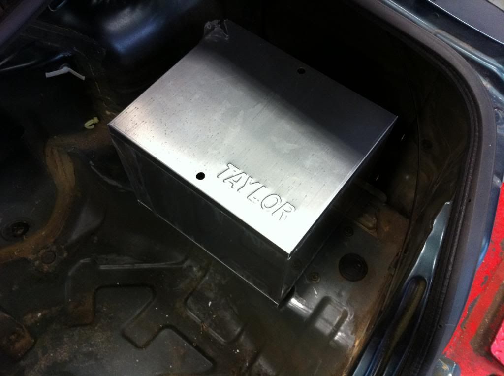
To keep as much weight off the front of the car I opted to relocate the battery to the rear. I purchased a Taylor battery box through ATech and my dad and I installed it one evening at the shop. It looks good back there and adds a significant amount of space in the engine bay. I went with a normal wet cell battery at this point. I may get a Braille or an Odyssey down the road.
Thanks for reading this post. It's probably too long but I wanted to get it all done in one sitting if I could. I'm sure I have forgotten a couple of things so I'll update as I recall. If you have any questions whatsoever feel free to pose them.
Once the wiring was complete and testing all of the electronics like wipers and lights, I was getting pretty amped to start the car.
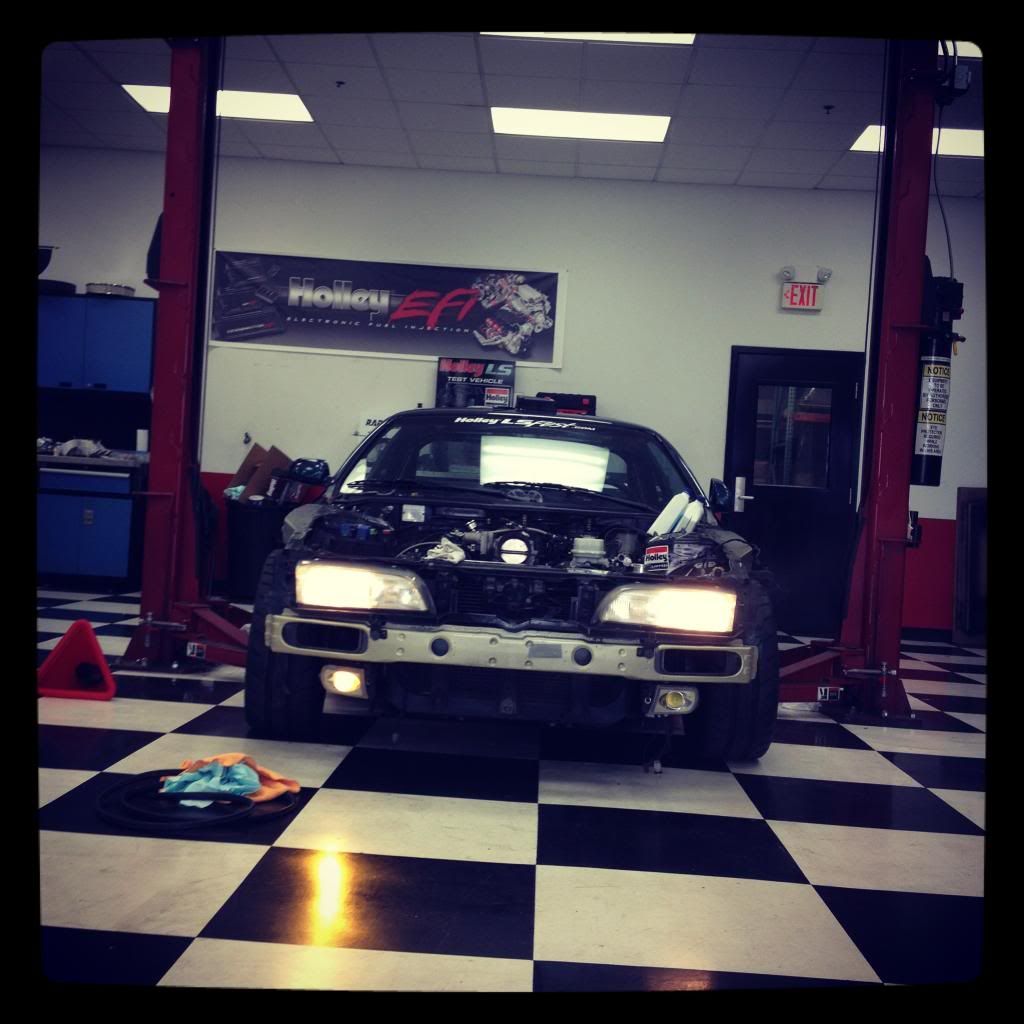
I filled the engine and trans up with the appropriate fluids and tried to fire it up. After some hunting around setting up the DBW pedal preference, making sure we had any air bubbles out of the cooling system, and that the thermostat was opening we had a running LS2!
Here's a video I took right after she started:
http://www.youtube.com/watch?v=yqMBR6C3C_c
After Project LS2 S14 was up and running it was time to build an intake, get it over to the shop for an alignment, and get all the other body parts back on the car. LS Fest was only about a week and a half away and I needed to drive the car around and make sure it was going to be capable of making some laps on the autocross.
I'll update with those items very shortly (I mean it this time).

Great write-ups; thanks for sharing the build w us.
Hey everyone,
After I got the car running, I headed straight to Advanced Auto parts to purchase a snub nose Spectre filter in order to keep crap from getting into the intake (don't worry, I drove there in another vehicle. It looked ridiculous so you won't be seeing any photos of it here.
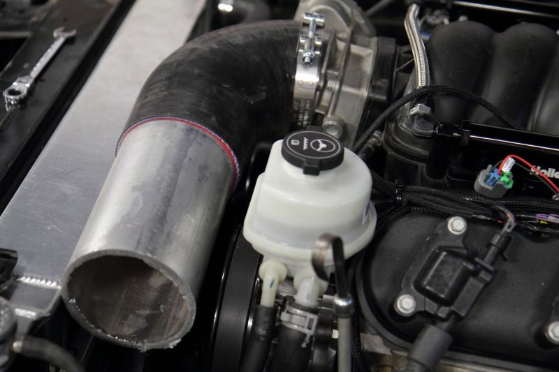
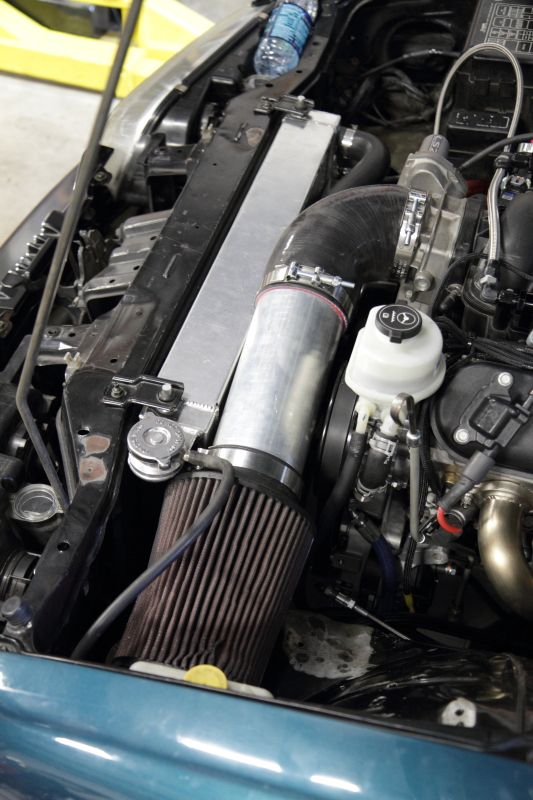
After that I took the car over to a Kentucky Turbo so Josh Jenkins could work me up a 90 degree 4'' intake to fit in the engine bay.
I also noticed after using the go pedal, the oil dipstick would get pushed up about a 1/4'', a sign of positive crankcase pressure, which is negative, lol. So I picked up a catch can off of a friend at work and planned on having Josh weld some Earl's AN bungs on my Holley valve covers in order to run Earl's Pro-Lite Ultra hose from the engine to the catch can. Unfortunately I do not know what brand this catch can is. I assume it's generic as it doesn't have a brand name on it anywhere.
Below are the install photos of these two parts of the build process:
4'' 90 degree elbow trimmed to fit the ever-tightening confines of the S14 engine bay.
Used 4'' filter installed until I could fill my pockets back up from spending money on other aspects of the car:
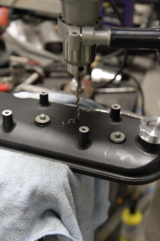
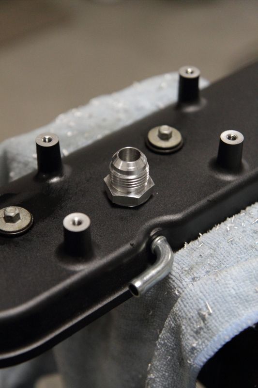
On to modding the valve covers:
Stock Holley LS valve cover pictured:
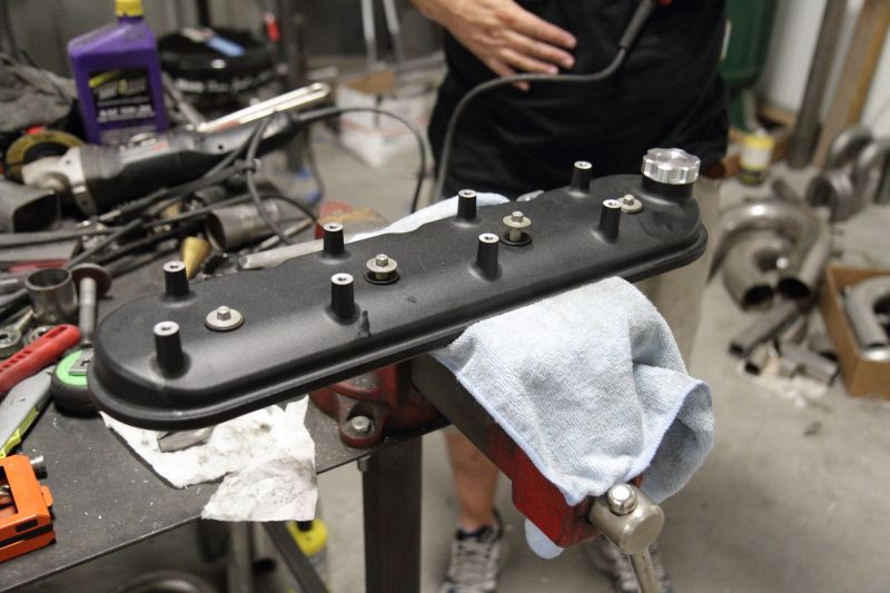
-10 Earl's aluminum bungs and Ano-Tuff fittings to be installed:
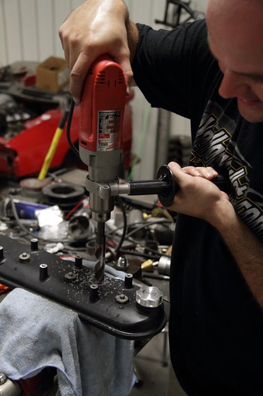
 Then we drilled the valve covers and then cleaned out the holes with compressed air in order to make sure shavings didn't get stuck in the baffles.
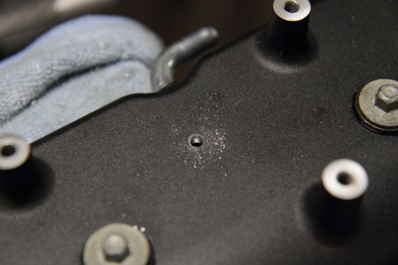
Starter hole:
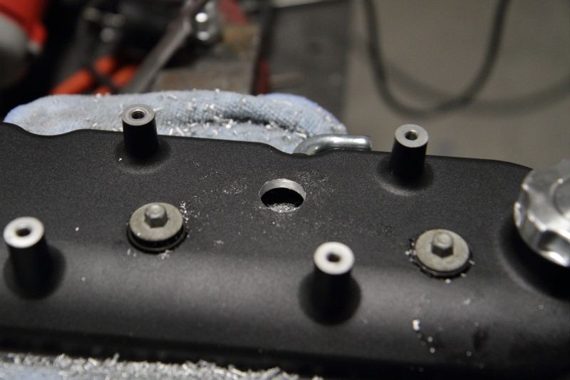
Final drill w/larger bit:
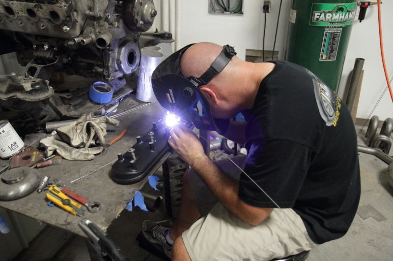
Then you have to grind the paint off the area in which you'll be installing the bung. If you're not familiar with welding, metal to metal contact is key in order to keep the welder from breaking up and ruining tips and having crappy welds.
Compressed air:

Placement of Earl's -10 bung over drilled hole (get your minds out of the gutter....)
Josh doing his thing:
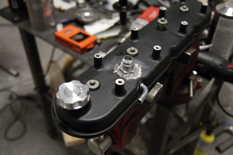
-10 bung welded to valve cover:
Stuck in the sink to cool off:
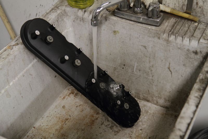
Re-installed on car after drying off:
I took the passenger side headlight out and drilled a couple of holes behind the headlight in order to fasten the catch can.
The entire setup installed:

this is what i love about this forum.....the different builds that are on here. ones like this being done in a dream shop and perfect and then you can click on another one and you have a guy working in his garage with kids and fam on a shoestring budget and doing a great job also......builds like this is great on a forum like this. it inspires all of us to do better.... cant wait to see it leave the shop under it's own power

This is so freaking cool.
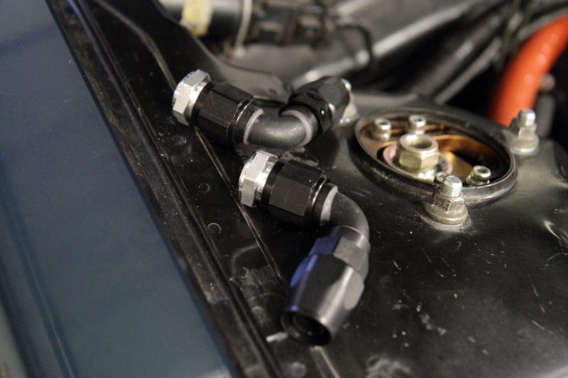
Alright, so I just realized that I neglected to include the fuel setup that I put together using as much Holley and Earl's components as I could. I'll have to include that in a future update.
After the ECU was installed and the intake and catch can were routed, I took it over to get an alignment. I've failed at determining how to embed video into this thread so here are a couple of links to videos of the car:
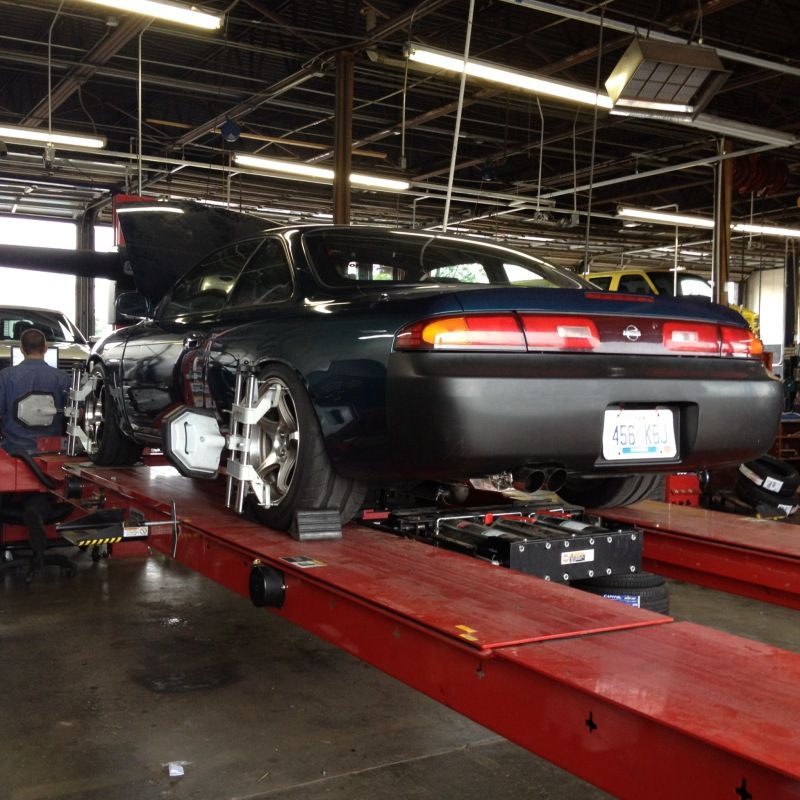
One at the alignment shop about to go on the rack (good for an idea of how the car sounds off idle): http://www.youtube.com/watch?v=Mb03AabYEHw
On the rack:
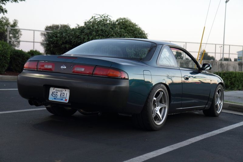
Then I went promptly to Chick-fil-A and noticed how nice it was to be able to take a photo of the car when it wasn't inside a checkered floor garage. My pictures were all starting to look the same!
After the alignment I took special care to stay out of the gas while I put 500 miles on the car to break in the clutch. I was also slightly irritated that the only leak I was having was a power steering leak. The reason for the leak was because apparently we do not have an Earl's fitting that will correctly adapt to the pressure side of the pump. I wrestled with various solutions to the problem right up to the day before LS Fest.
The day before the event I was surprised to discover that Advanced had a CTS-V power steering pressure line in stock for 70 bucks. As expensive as it was I needed to be able to use the car at our event so I purchased it and took it down to Bowling Green Rubber and Gasket (best store ever for random off the wall hose and fitting solutions) and had them adapt the fitting that went into the pressure inlet to a -6 line and -6 female adapter to mate with the metal OEM power steering line on the rack onto which I had previously brazed a -6 male adapter.
Following that I took the car out to Holley LS Fest! Whether you have an LS powered vehicle or not, this is an event that needs to go on your calendar (I'm not just saying that because I help put it on). I go to a lot of events every year and out of them all (trade shows & Formula Drift events included), this is an event you will not get bored at.
Not having anytime to test this solution and needing a backup plan, I called up KRC Power Steering and bought one of their crazy awesome, but CRAZY expensive LS circle track pumps with variable pressure capability to use in the event that my leak wouldn't stop. This was an overly expensive backup plan, but it was at least guaranteed to work. Over-night delivery on this was also not very cheap......
That night the cheaper $130 dollar Bowling Green Rubber and Gasket/Advanced Auto solution proved to work just fine and I was the new owner of a KRC pump that I really didn't need. I will make it known that I'll install this pump eventually as it is really cool and has the aforementioned ability to change the flow rate of the pump.
On to LS Fest.....
I had to work the entire event, which meant I only got a chance to shake the car down on the autocross twice, but during those two runs I discovered a few things:
1) This car is freaking FUN!
2) I need to get a sway bar that will work on the car now that the LS is in there.
3) The car could be much faster with front tires larger than 235/40/R17's on 17''x8'' wheels
4) I need to roll and pull my rear fenders a few more millimeters on each side as the outside rear tire under full squat out of corners would rub like crazy.
5) Gas gauge isn't working.
In two runs I was half a second off the pace of a full purpose built 2nd Gen-Pro Touring Camaro with well over 700 horsepower, and 300 series tires on all four corners with remote reservoir Ridetech coilovers, etc. I hit a couple of cones on this video but not counting that I hit a 44.50 and the Camaro had been running consistently around 43.90. It's safe to say I was pleased, minus the four second penalty I received for sliding past the stop box at the end of the run....
Autocross view from the stands: http://www.youtube.com/watch?v=okL2eMtAbRw
Autocross view from the staging lane: http://www.youtube.com/watch?v=zQW2inK2TnY&feature=youtu.be I'll add more about the power steering, mainly pertinent images to help others doing similar builds, to this update later.

In reply to s14blane:
What a monster of a car!!! Great to see it on an auto-x car that quickly after being buttoned up.
Really impressive build. It LOOKS great, too. Looks mighty.
gamby wrote: In reply to s14blane: What a monster of a car!!! Great to see it on an auto-x car that quickly after being buttoned up. Really impressive build. It LOOKS great, too. Looks mighty.
Thanks Gamby! I appreciate the kind words!
In reply to s14blane:
That should have said auto-x course", btw.
I love seeing a vision come to fruition. It's gonna be fun to smoke some high dollar cars in that thing. ![]()
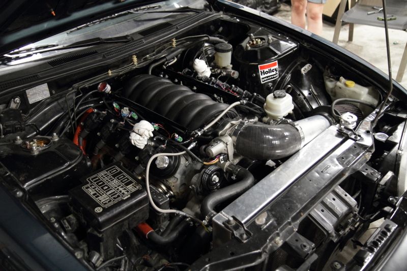
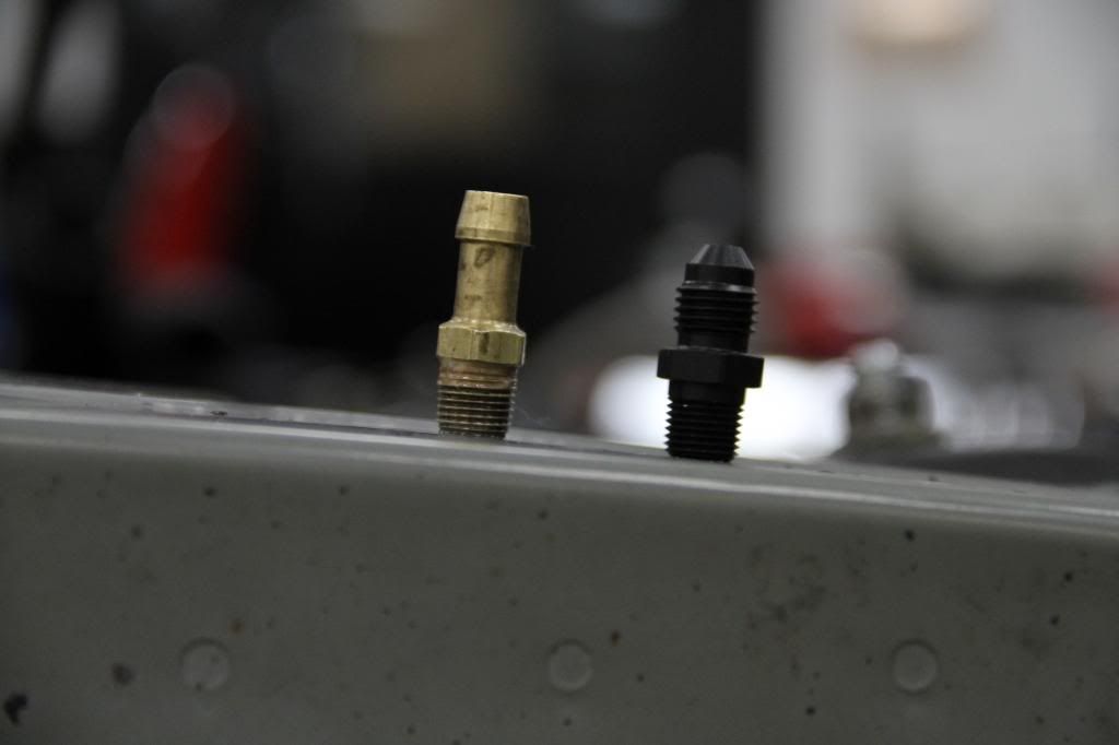
During the whole process of putting the car together, I found a part that would adapt the factory steam port setup to AN fittings on a fellow 240 enthusiast’s build thread (Broadfield on Zilvia).
I hopped onto the KRC Power Steering website and bought some for myself and used our Earl’s fittings to complete the setup.
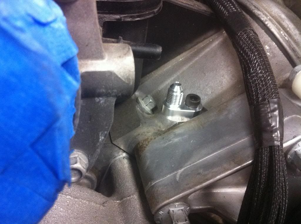
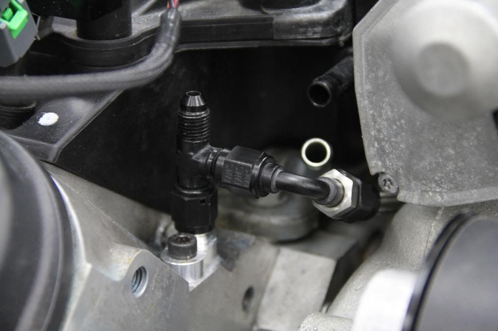
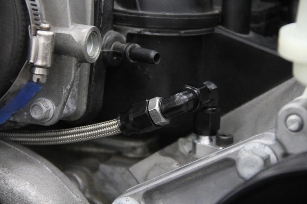
Check out how the steam port setup came together in the following photos using Earl’s Ano-Tuff fittings and Speed Flex -4 line.
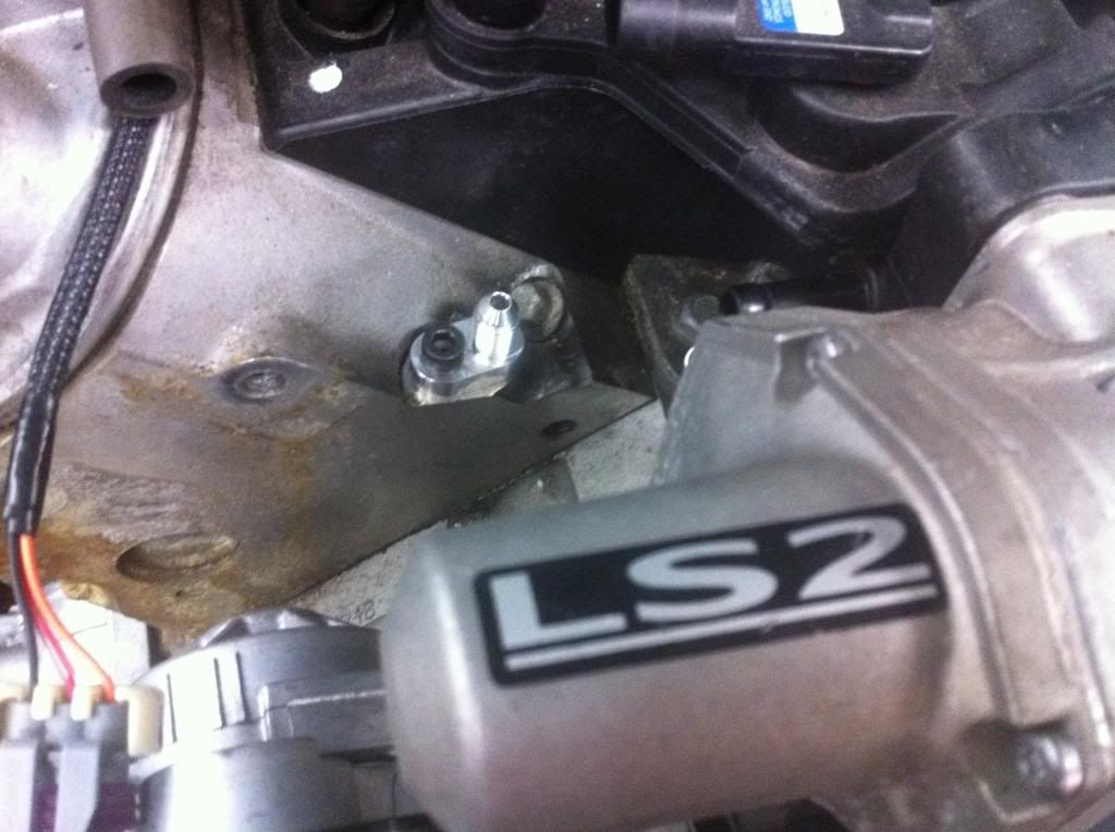
Adaptor from Radiator that accepted a regular push on hose:
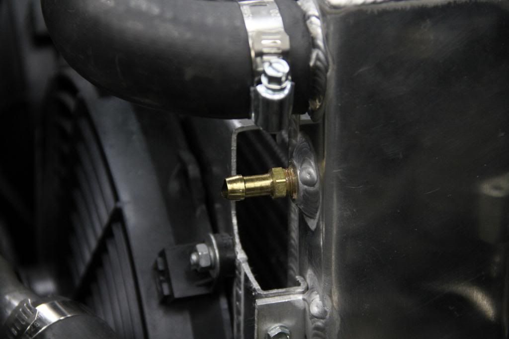
AN fitting I replaced it with:
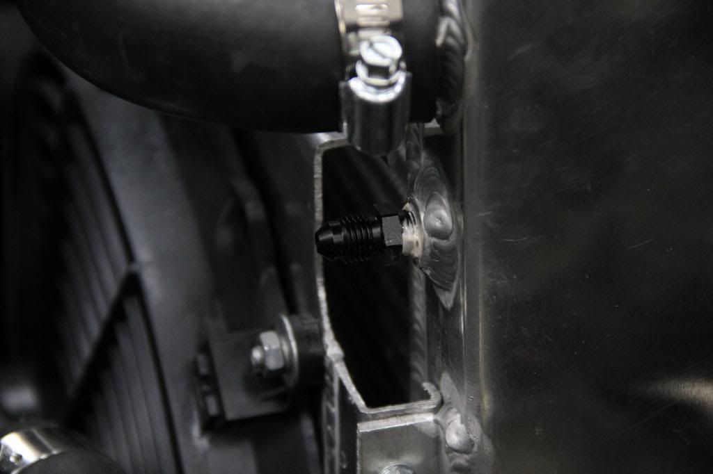
Comparison of both fittings:
NPT to AN adaptor installed with AN fitting on radiator:
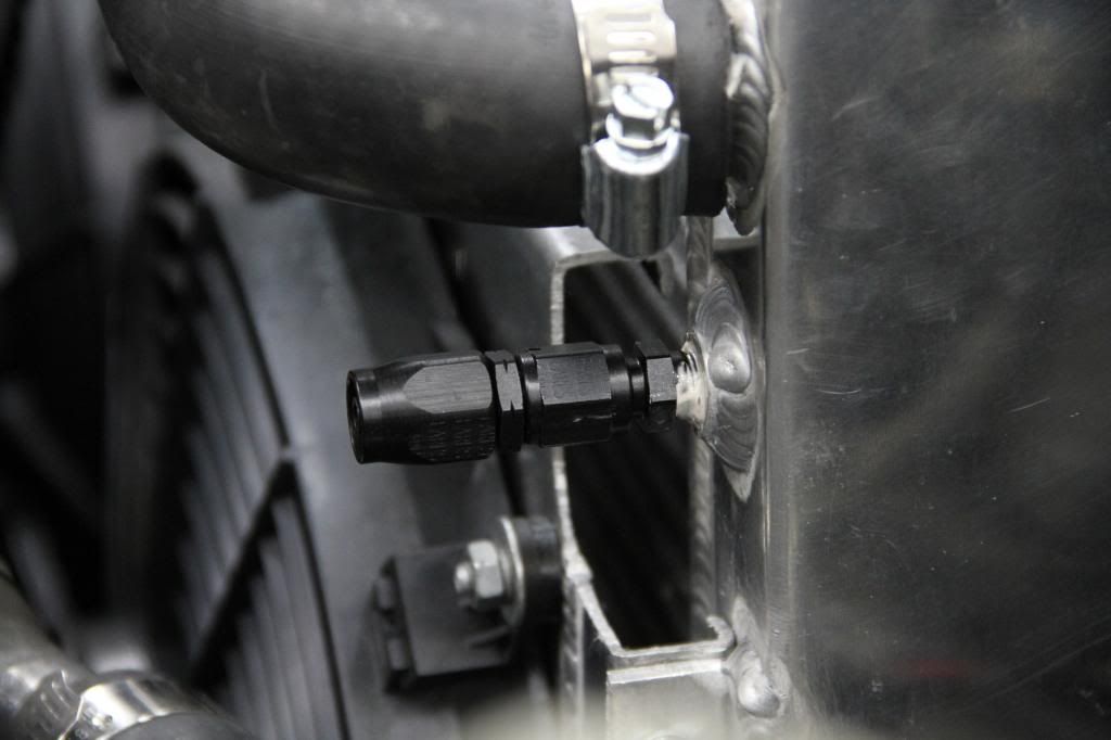
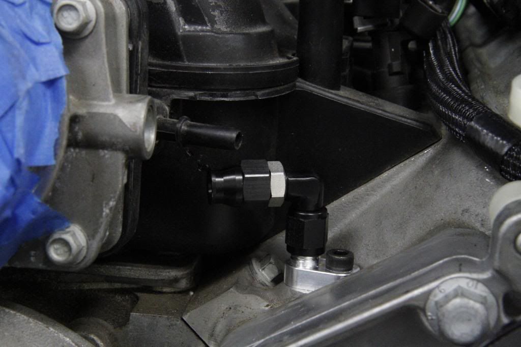
Passenger side setup:
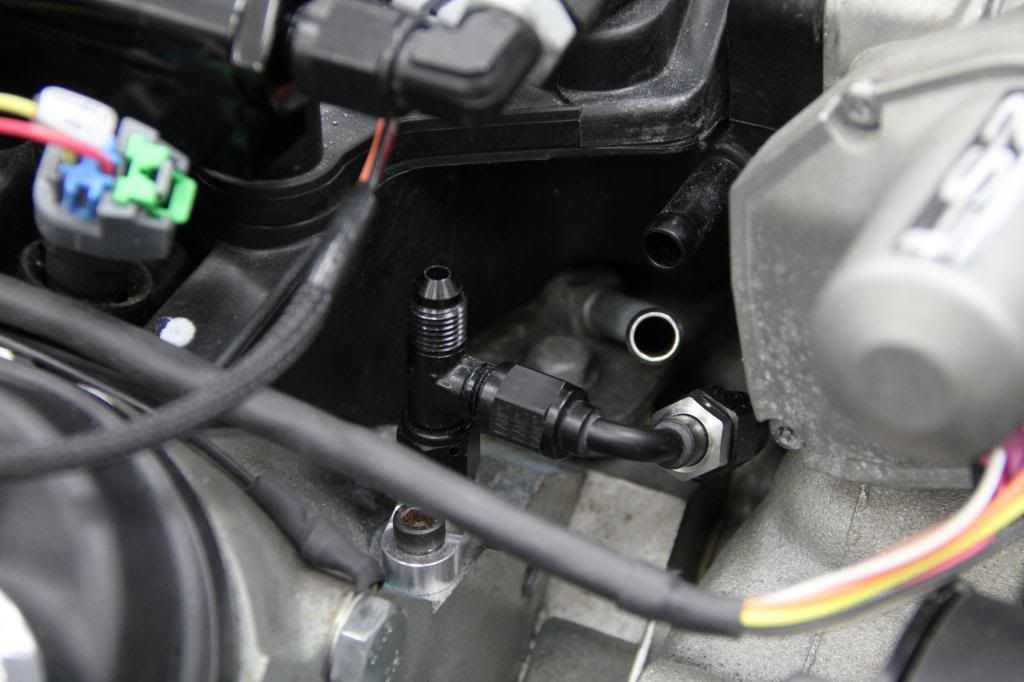
Driver side setup:
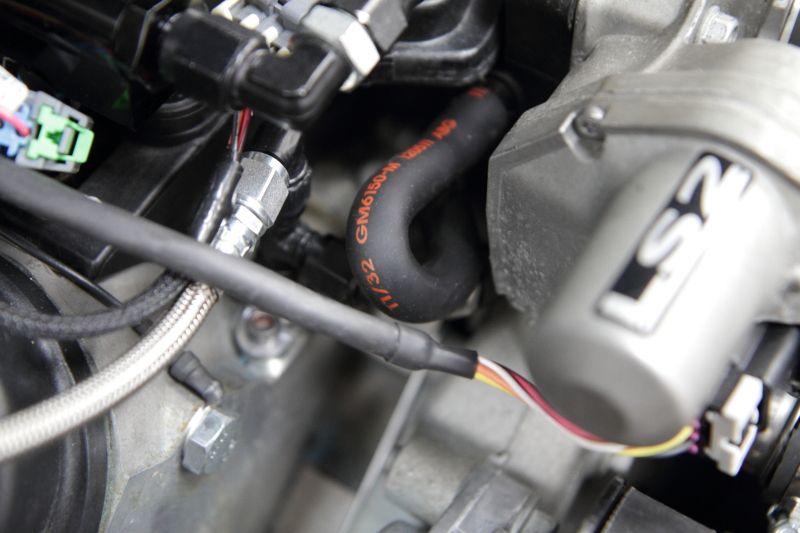
Crossover tube installed:
From the pictures above you can see two tubes on the passenger side of the engine that are not connected. The tube coming out of the intake valley cover and the black tube going into the intake manifold itself requires the installation of this GM crossover tube that I picked up from the “stealership”. Here it is installed:
Over the past couple of weeks I've been rushing to get things sorted on the paint and body side of things before I take the car on Power Tour 2013.
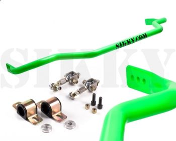
Things will, as per usual with all things that involve automobiles and deadlines, come down to the wire as I have to put the car back together entirely after paint including installing the drivetrain and wiring. I also need to purchase a Sikky sway bar, and hopefully install some softer spring rate springs front and rear on the Stance coilovers that currently reside on all four corners.
That and I have yet to install the 3.69 Q45 rear end and J30 axles that I have in the garage as well.
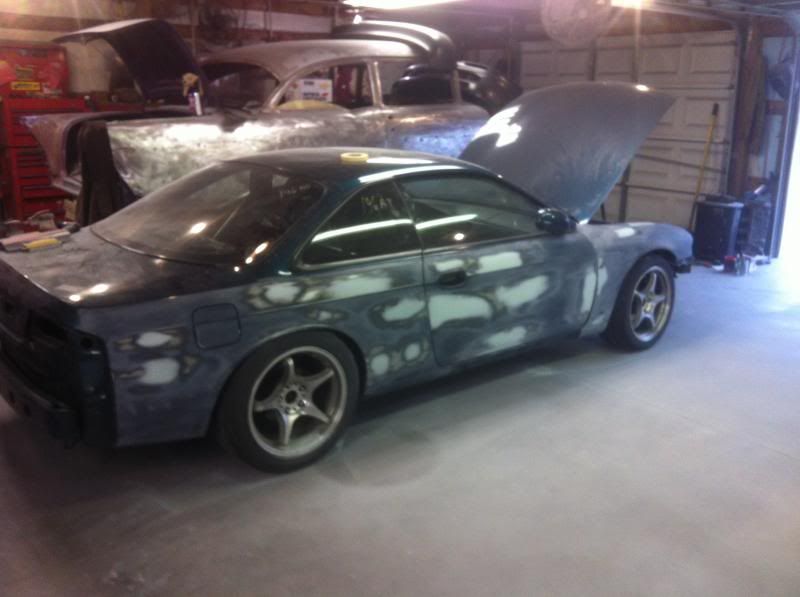
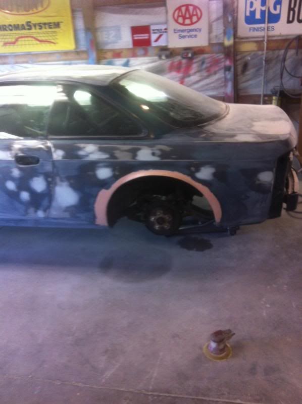
While paint hasn't yet been sprayed yet, we're making some headway on the exterior of the car by way of primer and many of the unneeded holes in the engine bay have been filled along with those left over from removing the factory spoiler from the trunk lid.
The idea is to have a super clean version of an OEM appearing Nissan 240sx, which is why I'm even respraying the car with the factory OEM Blue Emerald Pearl paint code. Can't wait to see how this car looks when it's done.
On to the photos:
Prep is key. The car had a managerie of dents and dings on all four corners and had been keyed by someone during the years it was "maintained" by a previous owner. Lucas texted me the other day and told me there were 64 dents total.
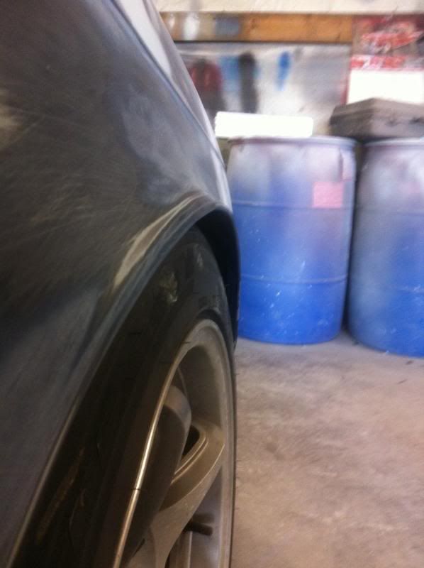
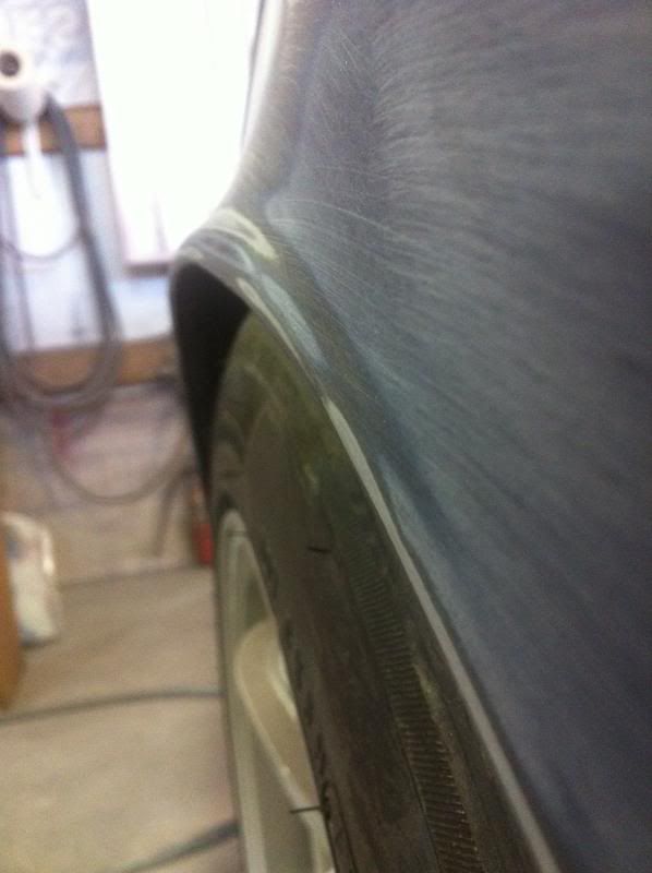
The other item that needed to be addressed was the rear quarters. While you may recall I used an Eastwood fender roller on the rears a while back, those actions proved not enough when I shook the car down at LS Fest. The car's outside rear tire would absolutely howl when the suspension loaded coming out of a corner so I needed some more clearance for sure.
Lucas was able to create another .5'' of clearance on both sides by hammering out and reshaping the quarters with another use of the Eastwood roller. The result is something I'm more than satisfied with.
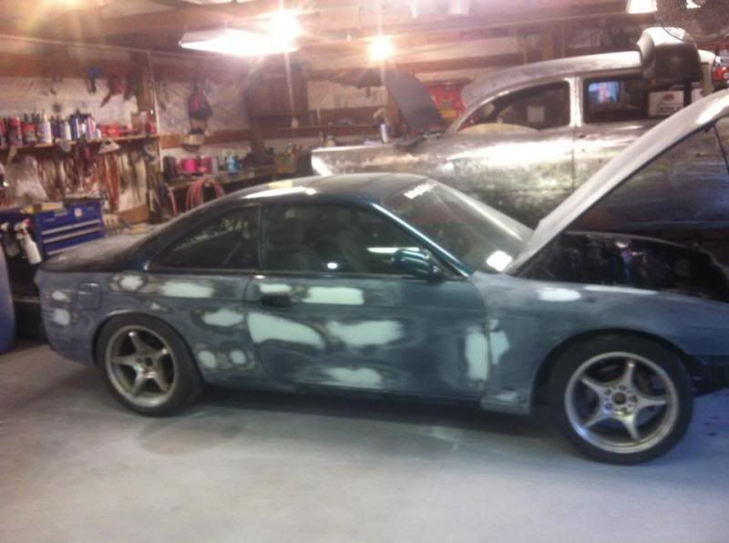
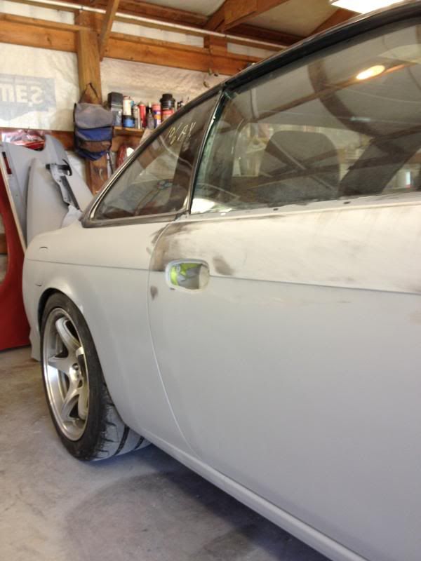
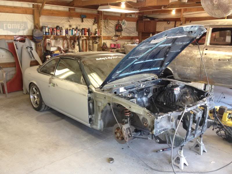
Saturday I got a chance to drive a county over and see how things were progressing.
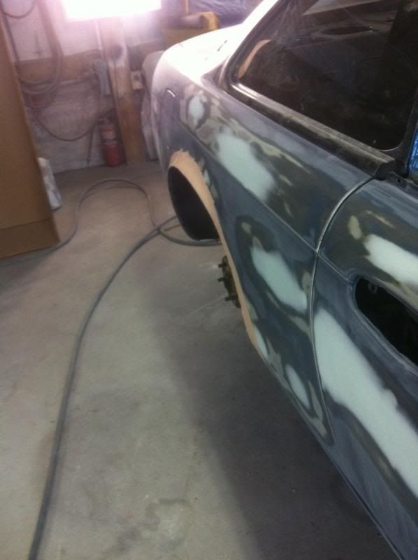
Most of the car is primered with a bit more work to do in other areas. It will be primed once again and allowed to cure while the engine bay is being finished out. Then paint will be applied all at once in order to reduce variation in color between body panels.
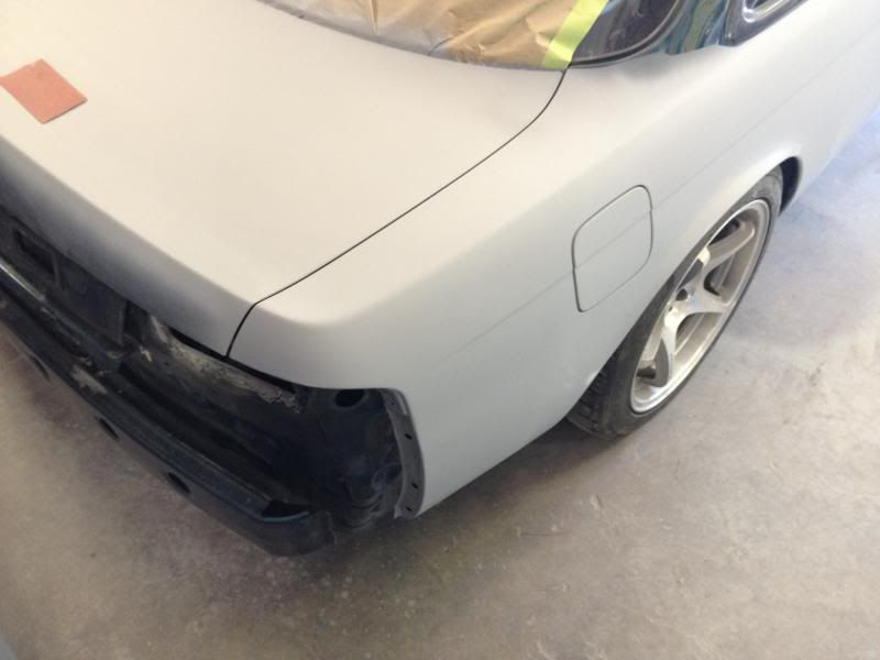
The rear wheels were back on the car and I have to say I love the look:
Rear trunk lid holes are gone:
The first time I found a need to jack my car up to get under it I was much dismayed to find out that someone had failed to use the proper jack points and had mashed up the underside of all four corners of the car at various points in its life. I wasn't even able to get the bottom fender bolts out when I was taking the car apart the first time because they were so creased.
Lucas was able to remedy all of that to it's factory appearance and functionality. Re-installing the fenders ought to be a cinch.
Some of the filled in holes that I no longer had a need for:
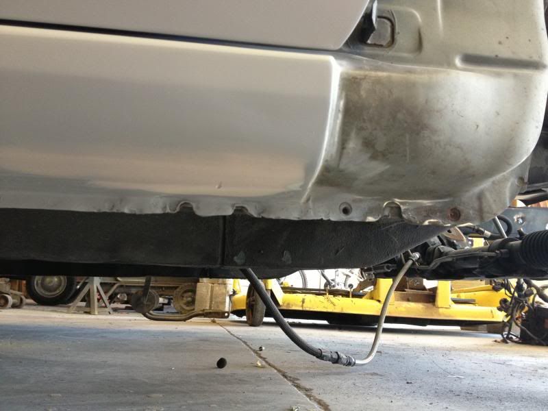
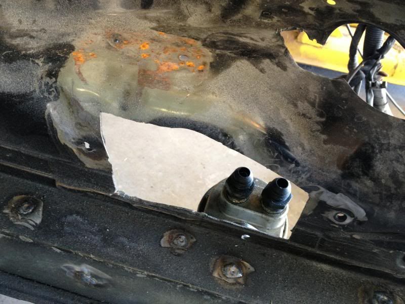
This hole that I jigged out of the side of the car aids in allowing the oil feed and return lines to the Earl's remote mounted oil adaptor that I have installed on the inside driver wheel well of the car. Lucas will be fashioning some sort of a shroud that will cover up the hole whilst allowing the lines to reach their destination and increase the aesthetics at the same time.:
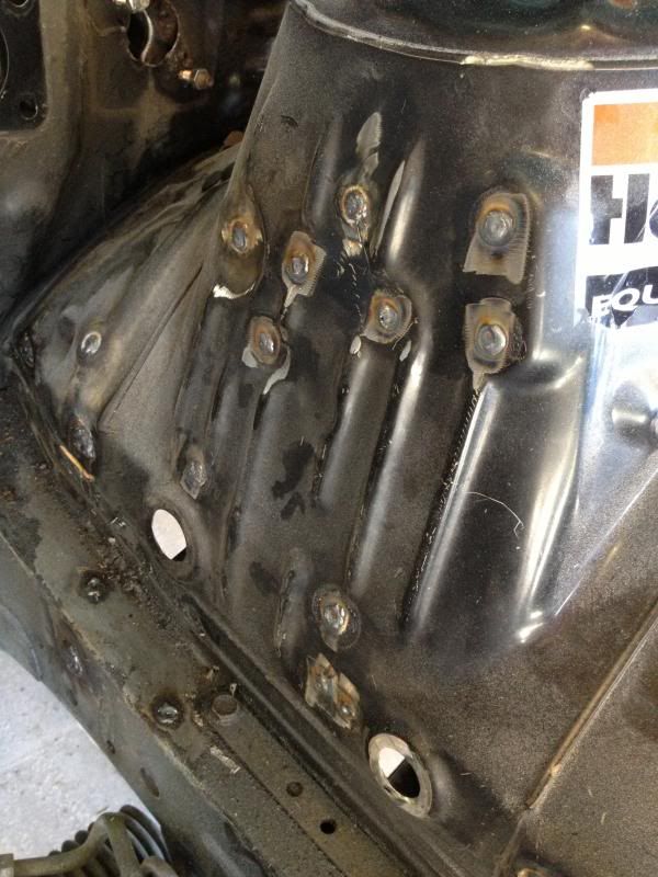
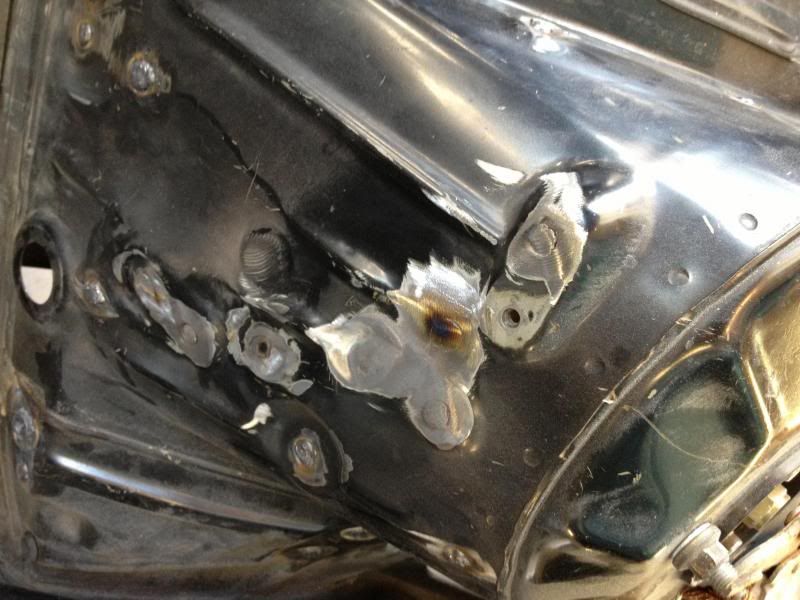
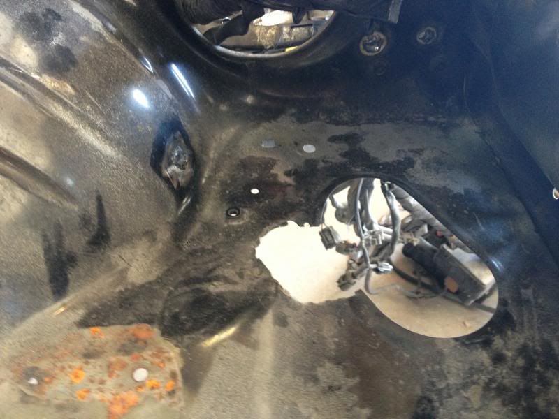
Here is another problem area that I was sad to find the first time I popped the hood open on the car. When the owner before me wanted to turbo charge the car and put in a front mount intercooler, apparently he didn't have time to go get a proper hole saw so a drill bit was used multiple times to eventually drill enough holes that he could hit out a "circular" shaped hole for the pipes to go through. This was done on both sides and will be filled in with fresh metal before the bay is complete.
Driver side:
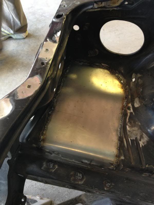
Passenger side metal already in:
That's all I have for now. I'll have more to share next week!

Where's the drooling emoticon?
![]()

So I probably should've gone to bed about an hour and a half ago, but I made the mistake of starting to read your thread...
Beautiful build! Thanks for all of the pictures - for someone like me who has a conceptual understanding at best, it was awesome to really be able to see what you were describing!
Can't wait to see what it looks like with a fresh coat of paint... It's going to look incredible. What a monster.
Are you going to do anything to the brakes? It seems to me that you'd want something with a little more bite to bring down the ridiculous speeds this thing is going to be capable of.

Amazing progress on the car Blane!!! I can't wait to see the finished project :)
Ps, if you want to win the autocross at LS fest, holla at your boy :p
This is among the most comprehensive swaps that I have ever seen. Very well done.
Mitchell wrote: This is among the most comprehensive swaps that I have ever seen. Very well done.
Thanks Mitchell, It'll be more comprehensive yet once everything gets back together!
Spoolpigeon wrote: Amazing progress on the car Blane!!! I can't wait to see the finished project :) Ps, if you want to win the autocross at LS fest, holla at your boy :p
Thanks Stephen! You gonna be at LS Fest regardless?
Huhmanbeing wrote: So I probably should've gone to bed about an hour and a half ago, but I made the mistake of starting to read your thread... Beautiful build! Thanks for all of the pictures - for someone like me who has a conceptual understanding at best, it was awesome to really be able to see what you were describing! Can't wait to see what it looks like with a fresh coat of paint... It's going to look incredible. What a monster. Are you going to do anything to the brakes? It seems to me that you'd want something with a little more bite to bring down the ridiculous speeds this thing is going to be capable of.
Thanks for the kind words Huhmanbeing! Thanks for mentioning the brakes. I've actually already taken care of that to some extent. One of the first mods I worked on doing was upgrading to the 30mm 300ZX aluminum four piston calipers up front with Hawk HP pads and new rotors, along with the Z32 master cylinder.
I have some photos of that on my personal blog: www.blaneburnett.tumblr.com if you want to have a look see.
UPDATE: I should be receiving my Sikky sway bar in the mail tomorrow. Can't wait to get that installed although I think I may change it's color as the electric green won't necessarily jive with the paint scheme of the car at all.

Very nice build. Definitely a lot of good work put into this.
In reply to Harvey:
Thanks Harvey! I appreciate it! I just found out from the painter that I'm going to have about two weeks to get the car back together before we ship out for Hot Rod Power tour so I'm a bit nervous at this point. But I'll make it happen!
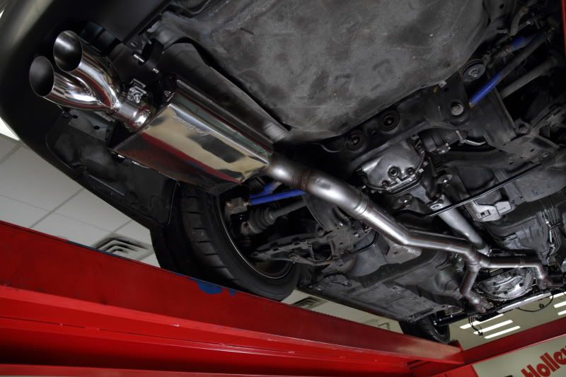
In other news....Hooker headers is about to release the exhaust system pictured here for S14 Nissan 240sx chassis that have GM LS cars installed between the frame rails. This is a direct bolt in kit for those cars that utilize our Hooker engine mount swap kit for LS engines as well as our Hooker LS swap headers for the S13/S14. It'll also work on other cars that are utilizing other manufacturers swap kits with some degree of fabrication for fitment.
s14blane wrote:Spoolpigeon wrote: Amazing progress on the car Blane!!! I can't wait to see the finished project :) Ps, if you want to win the autocross at LS fest, holla at your boy :pThanks Stephen! You gonna be at LS Fest regardless?
I hope so, but new scheduling system at work makes the chances look pretty slim at the moment. :(
I just recently made the decision to keep the heat down as much as possible inside the cabin of the car, which mainly includes installing A/C. I believe I'll have to wait until after Power Tour (ironically when I'll be wanting/needing A/C the most).
One of the products I'll be installing on the firewall and throughout the transmission tunnel to aide in keeping heat transfer from the engine bay to the cabin is called "Reflect-A-Gold" from Design Engineering Inc.
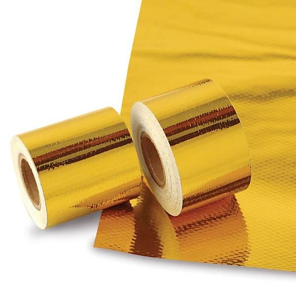
Quoting from their site directly, it boasts these features:
"Reflect-A-GOLD is a metalized polyamide polymer laminated glass cloth with a high temperature pressure sensitive adhesive for use in extreme temperature swing environments. It is lightweight and easy to apply and remove.
Highly effective material for firewalls, fuel cells, engine covers, under hoods, engine compartment, bulk heads, seat bottoms – anything or area that needs protection from heat."
I think it is effective to temperatures up to 375 degrees Fahrenheit, so it should be more than capable of keeping the extra heat from an additional exhaust pipe down in the cabin.
While on their website I also ordered up a set of their Titanium "Protect-A-Boots". I'm not going to lie, as I first saw these on a friends car (Wish you still had that S14 Jesse), and I thought they looked awesome., but they also serve a functional purpose as well.
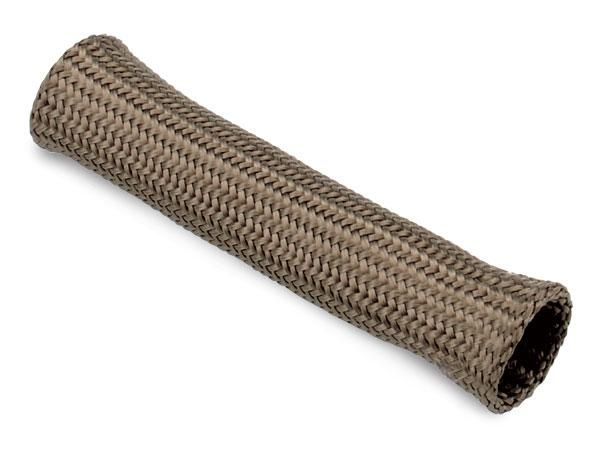
Pulling from their site the Protect-A-Boots provide: -Ultimate heat protection for spark plug boots -Withstands heat up to 1800°F (983°C) -Universal fit for most straight or angled boot -6" length available in 2 and 8 packs -Constructed of lava rock for long lasting strength & durability -Resistant to most abrasions, chemical & contaminants -Cool carbon fiber look
All of which make them a perfect fit for this project.
The Sikky front sway bar came in the other day and I'm starting to realize that I've got A LOT of work to do/parts to install before making Power Tour, so more than likely I'll be buying some pizza for friends and asking for two or three extra sets of hands before this is all over.
I also ordered a rear driveshaft seal (terminology???) to install in the back of the T-56 transmission and I'm also going to have a driveshaft shop a county over shorten the driveshaft that I currently have because it is presently a tad too long . I have noticed that it's pushing on the back of the seal on the trans and creating a leak. Not knowing if the leak is coming from the driveshaft touching the seal or if the the seal itself has seen better days I'm taking appropriate measures and removing both problems.
I have admittedly been driving the car without a speedometer and tachometer for a few months while I test the car out and make sure that all of the drivetrain is solid. The only gauges that I lost from doing the LS2 engine swap were the speedometer, tachometer, and coolant temp. I'll have to install the Nissan coolant temp sensor if I want the factory gauge to work on the cluster, and I'll hopefully have time to remove that from my to-do list before my time is up and we're on the road. I'll definitely be working on getting those gauges working prior to Power Tour with the help of these two boxes from Dakota Digital:
The Dakota Digital SGI-5 which is a Universal Speedometer Signal Interface.....
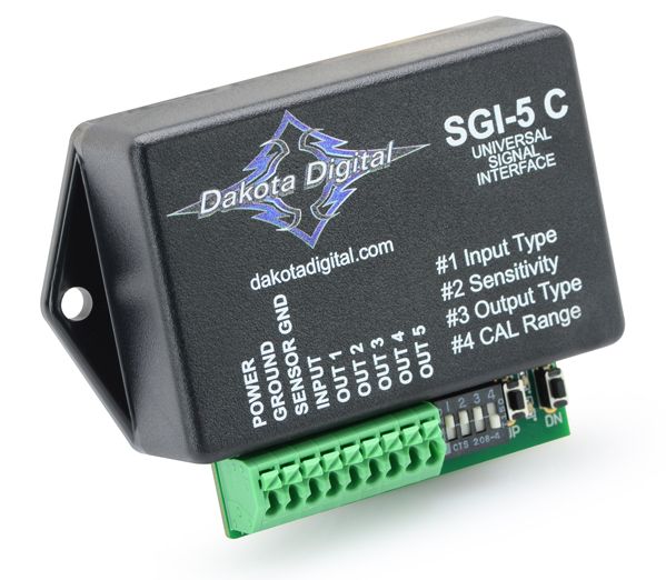
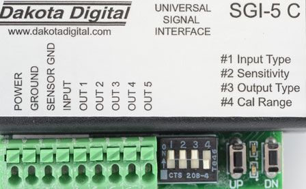 (pics courtesy of the Dakota Digital website)
....and the Dakota SGI-8 Universal Tachometer Signal Interface:
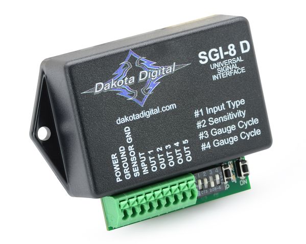
This box is the perfect solution for those that have done or in the process of doing an engine swap and need to make sure the factory tach signal can be made to speak the same language as the new drive-train you've installed.
These two converters will be responsible for making sure the signals that the transmission is sending out are able to be converted to a signal that is familiar to the factory Nissan gauge cluster.
The SGI-5 is a unit that is responsible for handling the conversion of speedometer signal and calibration. It can adjust a speedometer pulse rate up or down and is great for recalibrating a vehicles speedometer in the event that you've changed rear end gearing, put on taller tires, etc. I'll talk more about that later.
FYI, the SGI-8 is very capable and can handle most engine swaps going into most chassis. The only family of vehicles the SGI-8 is not compatible with are '86-91 VW Vanagon's and other similar models.
Expect an update on all of these items as soon as I get the car back from paint!
You'll need to log in to post.


