


You have no idea how mind blowingly cool this is to most of us...

You have no idea how mind blowingly cool this is to most of us...

Continues to be a cool build.

Autolex wrote: So; does the SS Turbo motor/trans fit in this chassis too?
We aren't completely sure if the SS powertrain will fit, but we think it wouldn't take that many modifications to get it into the car since we used the stock Cobalt subframe (we assume it would use the same mounting points). We'll have to check that out when its time to upgrade.
I used some adhesive seam sealer when I riveted in sheet metal to replace the rusted out tray of my bug. We've considered doing that on the floor but at this time we don't know when we might want to modify the car and would need to remove the floor. So we are just going to rivet it in for now.
December 6
If you look closely at the wiring in my previous log, you'll see that it was a mess. It was definitely better than when we first removed it from the car but it still needed to be tidied up.
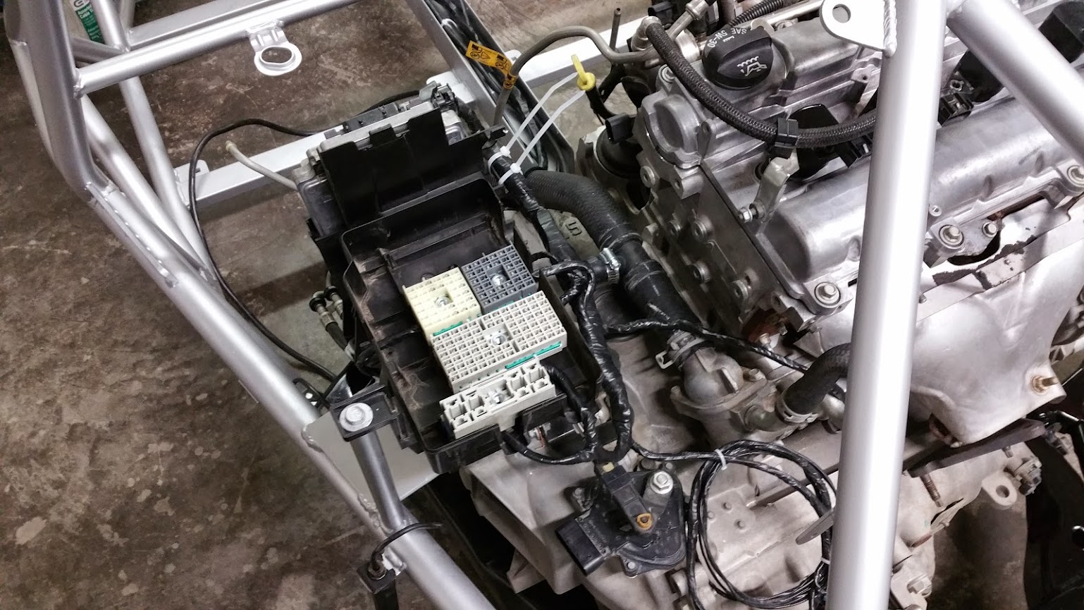
We unwrapped the original electrical tape, leaving small pieces at junctions where wires split from the main group. Then, starting at one end, we rewrapped all of the wires. Before long, we had a nice clean wiring harness stretching from the main fuse block near the engine all the way up to the BCM.
Fuse block:
Body control module:

Instrument and gauge wiring: (The wires hanging out are for switches, OBD II and other accessories)

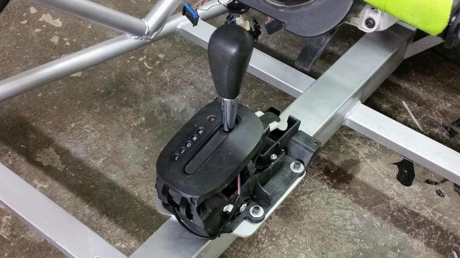
You can see how full the tunnel was getting. The last thing to join the brake lines, fuel line and thick bundle of wires was the shifter and shifter cable.
We routed the cable from the rear, slipped it through the tunnel cap and connected it to the shifter arm. The cap popped onto the tunnel and we bolted the shifter to the plate welded to the cap.
The green things are the atv hand grips we bought to make the OMG bar more ergonomic. They fit perfectly and will make white knuckle riding more comfortable for the passenger.

What's up with that not manual shifter?

In reply to Cool_Hand_Luke:
I am going to guess moving an auto from front to back makes the linkage for the auto easier to set up. From my google-fu it seems the auto in a cobalt has a linkage is just 2 cables.

Cool_Hand_Luke wrote: What's up with that not manual shifter?

Seriously though, you and your dad are doing a pretty thorough job on this build. Is it a prototype for something you'll be offering for sale?

Cool_Hand_Luke wrote: What's up with that not manual shifter?
do you even read the thread?
adoyle88 wrote: My dad says thanks for the compliments on his welding. Since starting the machine shop he hasn't spent as much time welding but I guess its like riding a bike. Our donor was an automatic. It does appear to have been a rental at some point in its life because we found a spare key hidden in a bag under the trunk carpet. Apparently this is common practice for some rental companies. We would definitely prefer to do a manual but this way the shifter and pedals were a little easier to deal with. Two of my brothers and I have stick shift 2009 Cobalts as daily drivers so perhaps in the future we could convert one or more of those. Mine only has 30k miles so it would be a great donor.

![]()
berkeleying amazing stuff!!!!!
As Mad_Ratel clarified, we chose an automatic donor to make things easier, but you'll be happy to know that the donor car I've already purchased for my car is a manual (it's the crunched up white car in the background of some of the photos).
nderwater wrote: Seriously though, you and your dad are doing a pretty thorough job on this build. Is it a prototype for something you'll be offering for sale?
We've known all along that we'd be building one for my dad and one for me, but after showing our build here and to some of the locals, we are considering making a few kits to sell on the side. From starting the aircraft machine shop 10 years ago, my family knows how challenging (and costly) it is to get setup to make parts for customers and the business portion is tough too. So for now, we are going to focus on completely finishing my dad's car, then mine. After that we'll figure out what we are going to do.
Back to the build:
December 7
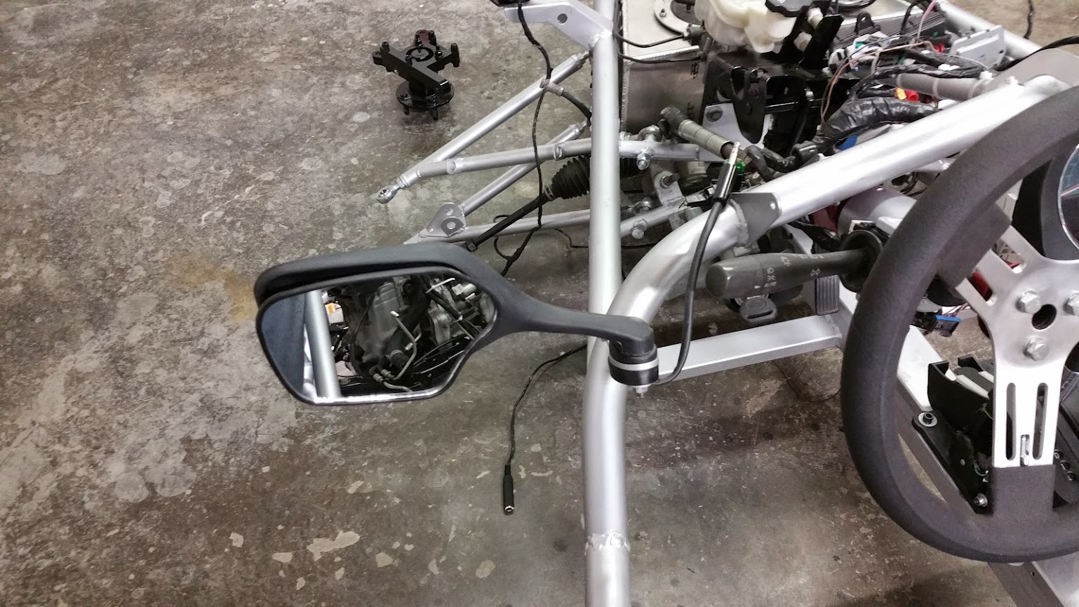
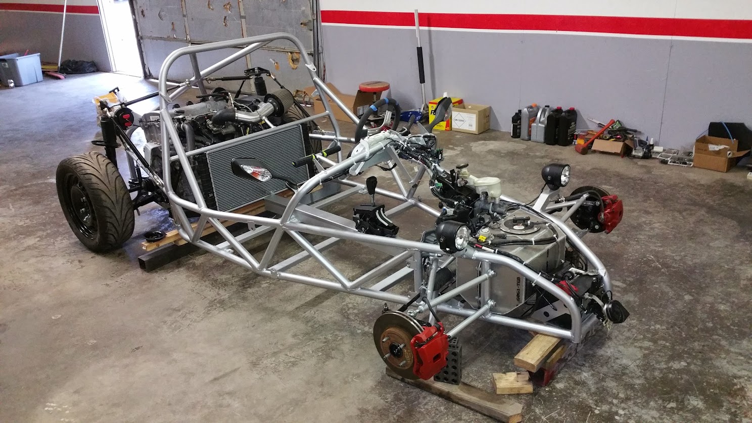
We installed the turn signals/side mirrors and my dad wired them while I installed the headlights. In case we want to change the mirrors or remove them completely for whatever reason, we used some 1/4 inch jacks to connect the turn signal wiring.
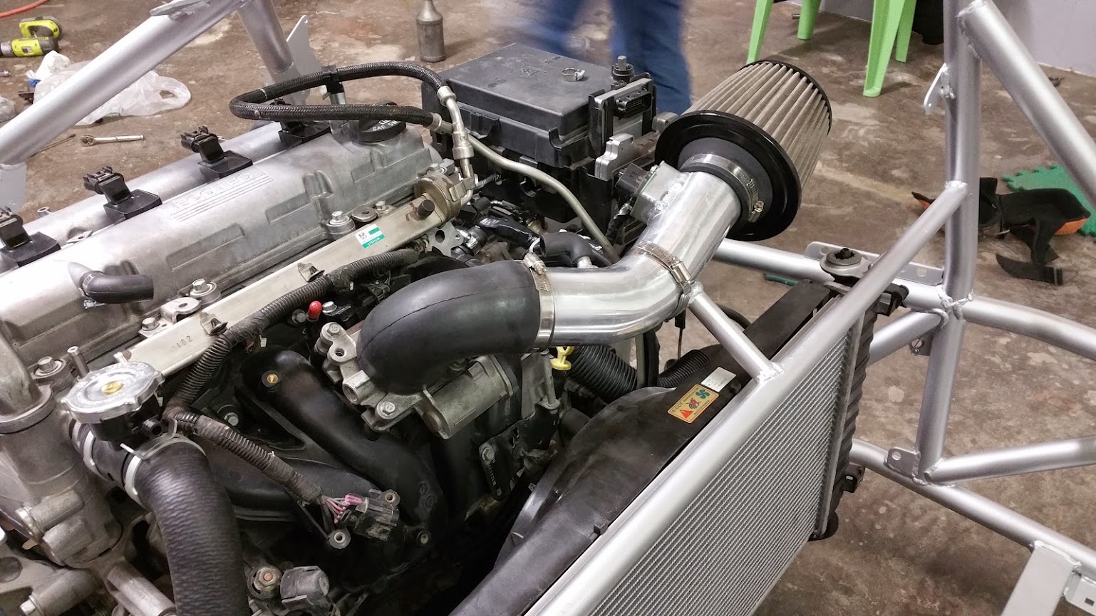
Next we slipped the radiator in and connected the transmission fluid lines and the engine coolant hoses. With the stock Cobalt coolant system, you filled the radiator through a large, hard to mount plastic reservoir. To avoid having to fit this tank to the car, we looked to the racing world and decided to use an aftermarket filler cap. We picked the highest point in the coolant system, which happened to be in a very convenient place near the passenger side of the cylinder head, and spliced in a tee shaped filler neck. We will be connecting the overflow vent to an aftermarket overflow tank.

The last thing we did was put on the air filter and intake tube. Don't worry, we did install the clamp around the rubber at the throttle body. Also, not shown in this photo is a metal tube that runs from the rubber elbow on the valve cover vent to the rubber elbow on the intake tube.

MOAR!
How does air get to the radiator?
Great work!
In that last photo you can see a rectangular tube in the bottom right. The floor ends at the back of that tube, leaving about a 10 inch opening across the full width of the car (except for where the tunnel is). In SolidWorks, it looks like the air flowing under the car lifts into this low pressure area on its own. Add in the suction of the fan and we think it will get enough air.
The Cobalt gauge panel gives a coolant temp readout so we will keep an eye on it and if it looks like it's not staying cool enough we will add air ducts from the side of the car.

There's no natural airflow at all on the radiator on a classic Mini, it's all done by the fan. FYI.
1/4 jacks for turn indicators, interesting idea. Easier to deal with than the usual automotive connectors for sure and very compact, but maybe not so much built for water intrusion. We already know it's a summer day car. It'll be interesting to see how they deal with vibration.
Next up in our build was the button panel. We needed a place to mount an OFF-ON switch (enable cruise control), 5 OFF-(ON) switches (horn, resume cruise/accel, set cruise/decel, info and enter), two switches from the donor (hazard lights and trunk release) and one knob from the donor (gauge brightness adjustment).
We made it so that it could mount below the gauge panel but we've already decided we don't like it in that location because it encroaches on knee space and makes it a little harder to grab the gear selector. When we remake the switch panel it will be two pieces mounted to the left and right of the steering column. It will be a little harder to reach but at least it would get the panel out of the way of your knees.
Although we will be scrapping this version, I figured you guys would still want to see it.
December 8
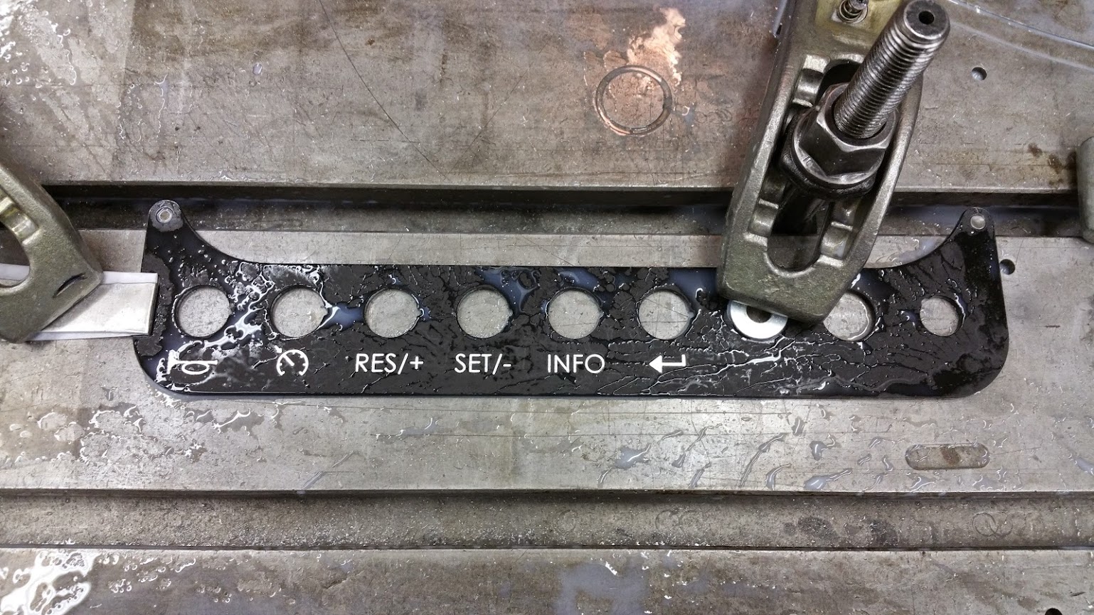
Six of the switches we used were not part of the donor car. They are just simple round toggle switches that mount through a 20 mm hole and click into notches that we cut in the backside of the panel. The trunk release button we reused from the donor was just as simple to mount but it required a smaller hole. The other two donor controls, hazard lights and gauge dimming knob, were harder to mount. You can see why in the photo.

The two square controls couldn't just pop through the panel. Instead, we had to cut square recesses into the back of the panel to center them and then we tapped the panel to use threaded rod to hold them in. We cut all of that, the holes to mount the panel to the car and the outside perimeter on the CNC.
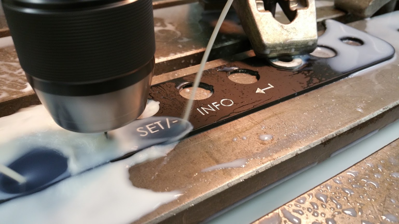
The switches we bought online are generic black plastic so unlike the donor switches that have labels on their face, you'd have no clue what each switch did. We decided that the best way to label them was to engrave the panel with the original icons/words GM put on their buttons.
To do this, we first painted the face of the panel black. While that was drying, we sketched the icons on SolidWorks and programmed the cuts. We carefully clamped the panel to the table without scarring the black paint. Then we used a small end mill to engrave the labels.
December 9
Next we machined out the plates that would hold in the square shaped switches. We used 4-40 threaded rod and nylon locking nuts to tighten the plates against the switches.
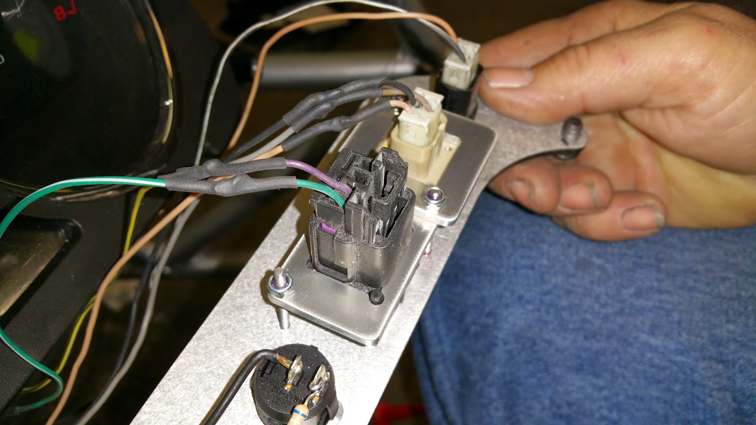
The next part was a little more technical. The cruise control and info buttons are all on the steering wheel in the donor Cobalt. Instead of running wires for each button, auto manufacturers use one set of wires and when you push a button it changes the resistance. The BCM sees this change and based on whatever resistance it reads, it completes the appropriate command.
We grabbed the buttons from the donor car and checked the resistance as we pushed each button. Then we found resistors that matched the values and soldered them to each switch.

For now we don't have the cruise control wired up because our donor Cobalt didn't come with cruise control. However, the cruise wiring was included (just not hooked to any switches), so we would just have to wire the buttons up with the correct resistance and have cruise control enabled via the OBD II port.
After we had wired up the switches we'd be using, we mounted the panel below the gauges.
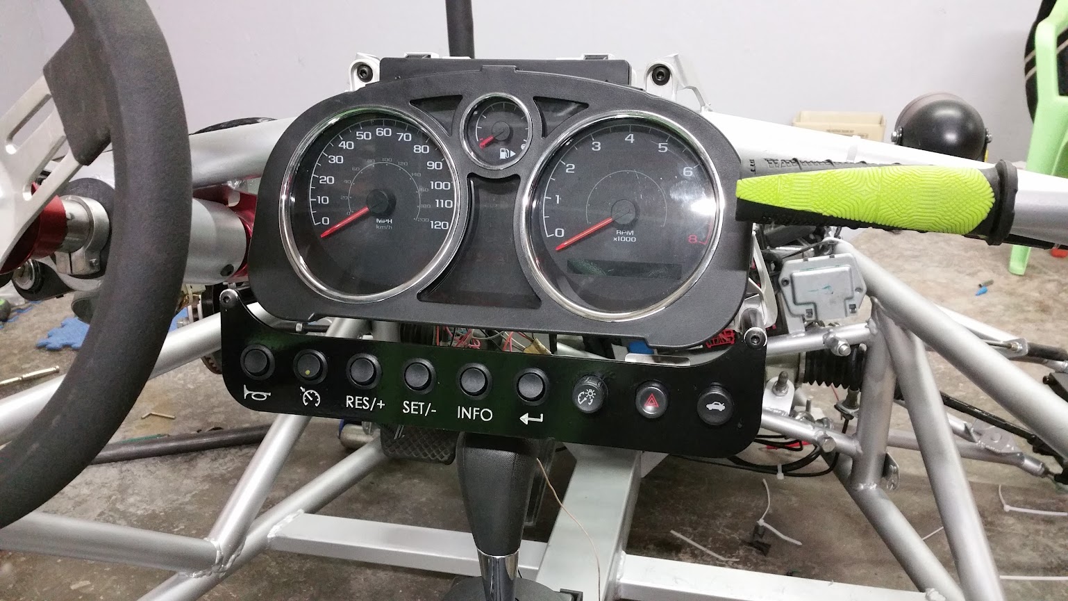
The photo makes the gear selector look closer to the panel than it really is. It is possible to operate the selector but its a little uncomfortable. We could make the panel fit the gauges a little better and get an inch or so higher, but it would still be too close to your knees. This is why we are going to relocate the switches.

Why not mount it above the cluster?
Unfortunately there isn't enough room up there because the nose comes all the way down to the cluster. If the buttons are too awkward to reach behind the steering wheel, we will try a different layout on my car. Realistically though, I don't think either of us is going to use the buttons enough to need them to be easily reachable.
why not put them down on teh center console?
dimness hazards and trunk could at least go down there.
or up behind the steering wheel. (since you wont be driving usually when needing those three.)
then place the cruise buttons on a panel to the left of the steering wheel.
I'd honestly leave them out for now and decide later if you really need the cruise buttons.
That's a good idea. Cruise to the left, dimmer, hazards and trunk on the tunnel and we could probably keep the info and enter button on a much smaller panel right under the display portion of the gauge cluster. Those buttons cycle through odometer, trip mileage, miles to empty, coolant temp and others like that. It'd be useful to have them near the readout. A small panel in the middle wouldn't be near our knees and we could tuck it up enough to be completely out of the way of reaching for the gear selector.

Fantastic build porn. Everybody's ready for you guys to throw down and start building kits. Once you finish the build, there's going to be a lot of tweaking and testing and relocating until you're satisfied the car has maxed out on potential.Then it's time for car # 2, after which you may be too busy or too exhausted to keep going. You could just publish a set of plans.

How easy is it to view the gauges from the driver's seat? I assume you thought of mounting the gauge directly above the steering wheel? If you did this, you could have a small panel of switches above the shifter, and maybe those switches you don't use much on a separate panel above the tunnel, as others have suggested.
I can't emphasize enough how impressive this is. I love it! Sign me up to the list of those interested in a kit! I'd love to build one of these. Sadly, my fabrication skills are still lacking, but I'd totally rock putting a kit together.
Just Wow!

Really like your build- the fab skills are awesome....hopefully my 7 will turn out as well.
Curious about your side view mirrors- where did you find those??
Devin
devina wrote: Really like your build- the fab skills are awesome....hopefully my 7 will turn out as well. Curious about your side view mirrors- where did you find those?? Devin
I'd like to see some pics of your build. Do you have a thread?
I got the mirrors on Amazon. They are replacements for a Honda CBR 1000RR. Here's a link for the ones we got http://www.amazon.com/gp/aw/d/B00C305EQK
I wish some of the machine shops local to here did work as fine as you do... great job man.
Jerry From LA wrote: Fantastic build porn. Everybody's ready for you guys to throw down and start building kits. Once you finish the build, there's going to be a lot of tweaking and testing and relocating until you're satisfied the car has maxed out on potential.Then it's time for car # 2, after which you may be too busy or too exhausted to keep going. You could just publish a set of plans.
the issue with this is the timeless problem every builder (except exocet) has. Everyone loves it but wants it at 1k a ready to put together kit..
Jerry From LA wrote: Once you finish the build, there's going to be a lot of tweaking and testing and relocating until you're satisfied the car has maxed out on potential.
You are absolutely correct. We've already found many things we want to improve upon during my build and we aren't even finished building this car. I am sure we are going to find even more when we start driving it on the road and track.
edwardh80 wrote: How easy is it to view the gauges from the driver's seat? I assume you thought of mounting the gauge directly above the steering wheel? Sign me up to the list of those interested in a kit! I'd love to build one of these. Sadly, my fabrication skills are still lacking, but I'd totally rock putting a kit together.
The gauge panel is pretty large so it makes it hard to mount it above the steering column.
Making kits is looking more like a possibility each day. We don't know about other cars like ours, but it feels like it is really easy to assemble. It'd be cool to offer it to people that don't have all the tools or shop area that we do.
December 10
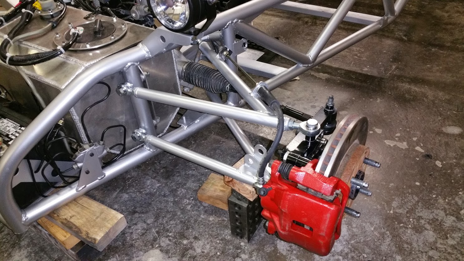
We had realized much earlier that our outer tie rod mounting location was too high, leading to a lot of bump steer. It was time to fix that.
The first thing we did was bolt on the steering knuckles, hubs and front tires. We left the coilovers off so that it was easier to move the suspension through its travel. Using our original tie rod location, we found that the toe changed nearly an inch over three inches of suspension travel. It toed out during compression and in during rebound.
The tie rod ended up needing to be moved down 3/4 inch. As best as we can measure, the toe now changes less than 1/16 inch over the full travel of the suspension.
We pulled the tire back off and installed the brake caliper.
Next we decided to assemble the rear suspension. We are using adjustable rods so that we can tweak the strut tower location when it comes time for testing. On my car we will mount the towers rigidly based on where they end up on my dad's car.
We had also installed the tail lights by this time.
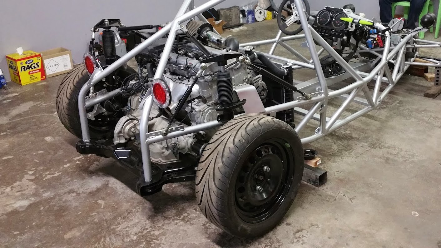
New tie rods to set the rear toe had not been bought yet so we stopped there.
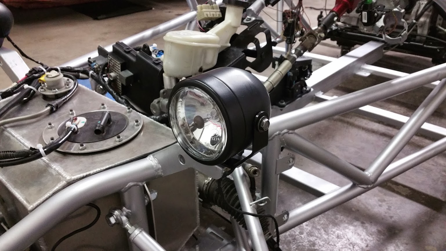
Oh, now that the photo reminded me, we mounted the horn in front of the battery. It aims down so that it doesn't blast back up under the nose and directly at the driver. We learned something interesting while mounting it. We reused the simple metal strap mount from the donor. It was shaped like an L with the long end mounting to the horn and the short end to the car. To get it to fit our car, my dad bent the long end 90 degrees so that it looked more like [.
We hooked it up and pushed the button and the car let out what I would describe as the sound of a dying goat. It was awful. We thought that maybe the horn was rattling against the frame but it wasn't. The only thing that seemed to help was unbolting it from the mount. When we did that, the horn sounded crisp and loud.
It seemed like the mount was the problem so we straightened it back out, bolted the horn back on and sure enough, it sounded great. Apparently the mount needed to be less rigid than the [ shape made it. So we bent it into a continuous curve, forming a C shape. With it being less rigid, the horn worked just fine.
You'll need to log in to post.


