
While the maroon on black interior has grown on me, it was originally a compromise. I had most of the black interior I needed, but no seats. My maroon GXL seats were in nice shape, so I just decided to roll with it and install the maroon insert into the hybrid dyed / factory black door cards. I briefly considered reupholstering my seats in black, but I ran into two problems:
1. They're in nice shape. I usually only dye / alter interior parts that are in poor shape. For nice parts, it makes more sense to resell them and just buy the black parts if they are available.
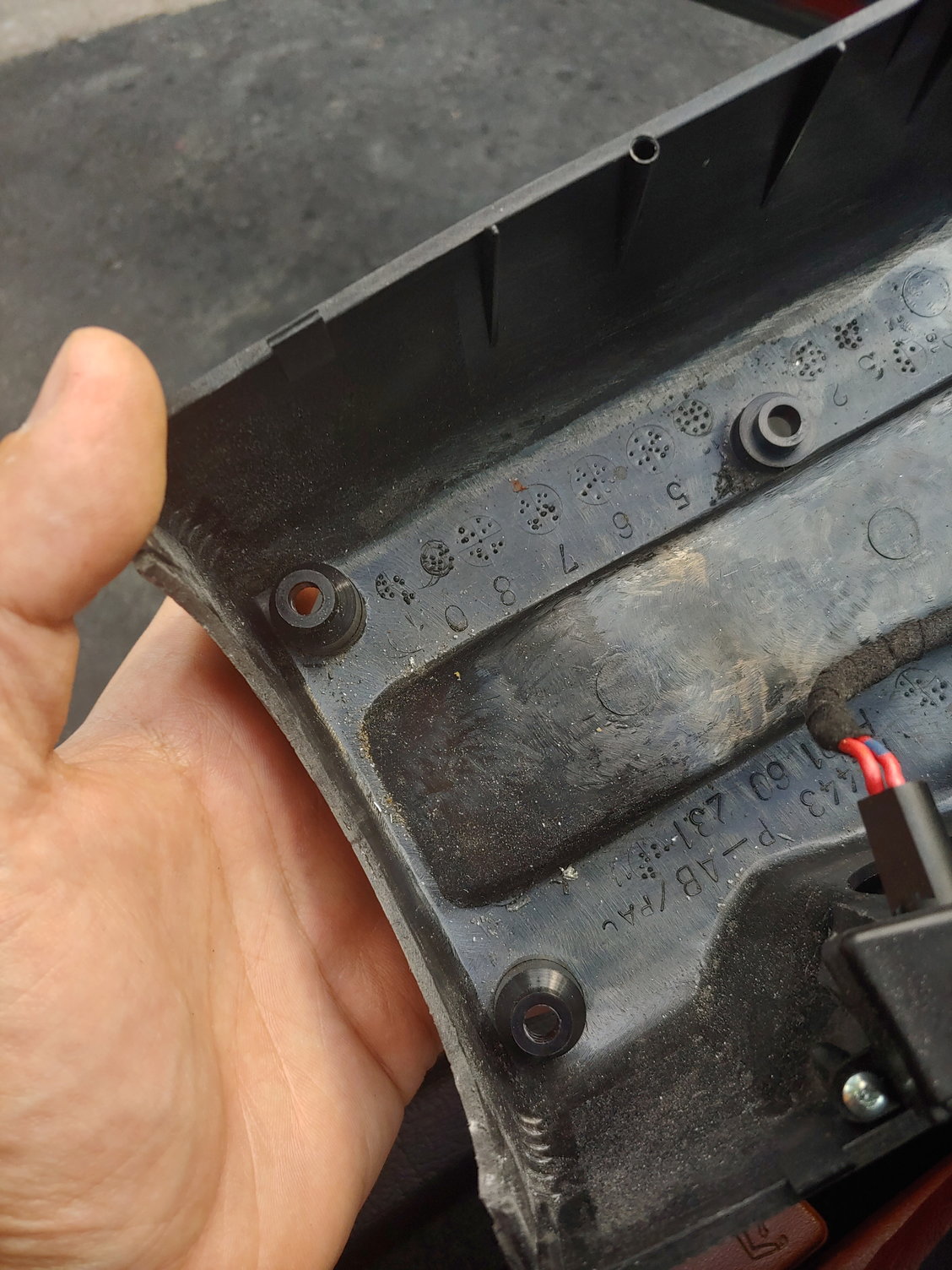
2. They're not quite perfect, so I don't want to invest anything into them. The adjustable headrest irks me for some reason I have yet to pin down, and I slide around through turns.
So it was fortuitous that the car I got all these other parts from had a reasonably O.K set of seats. These are the later style with the fixed headrest:
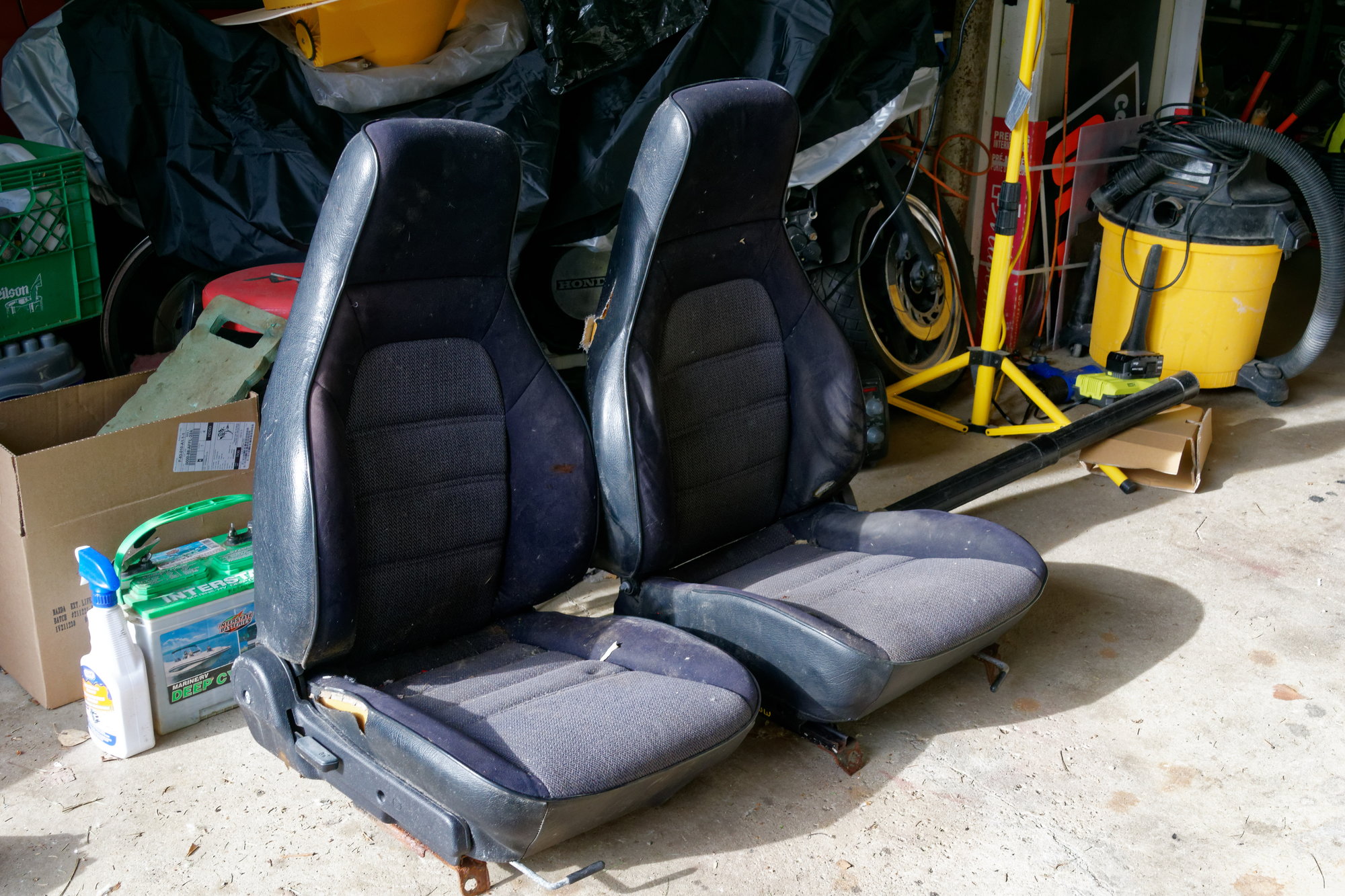
Torn and a bit gross, but hey, they were cheap. I thoroughly cleaned them, and they looked a bit better. Still not going to use them yet due to all the tears though:
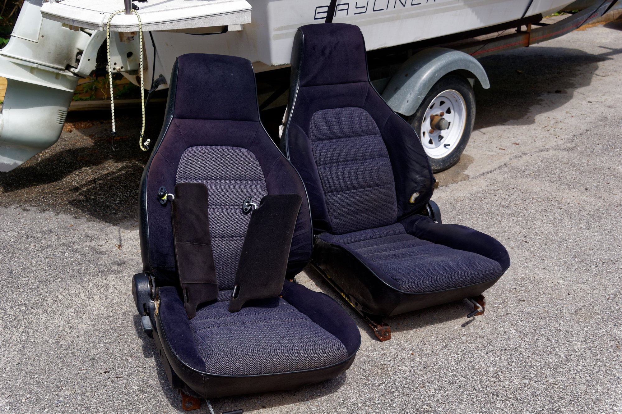
The sliders were very rusty and completely seized, so they went to the scrap metal bin. Then I wrapped the seats up very well and put them in storage for later. I want to reupholster them, but right now the turbo swap is the priority.
I also got these for a super good price:
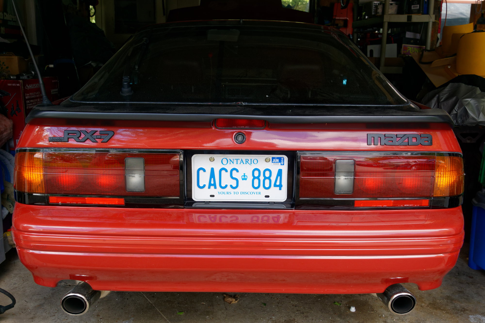
I already had a 99% perfect set of S5 tails, but the other car had a 100% perfect set. No scratches, no nicks, nothing. They look new.
I was able to flip my old set for a profit, which covered over 1/4 of the cost of the Turbo II drivetrain.
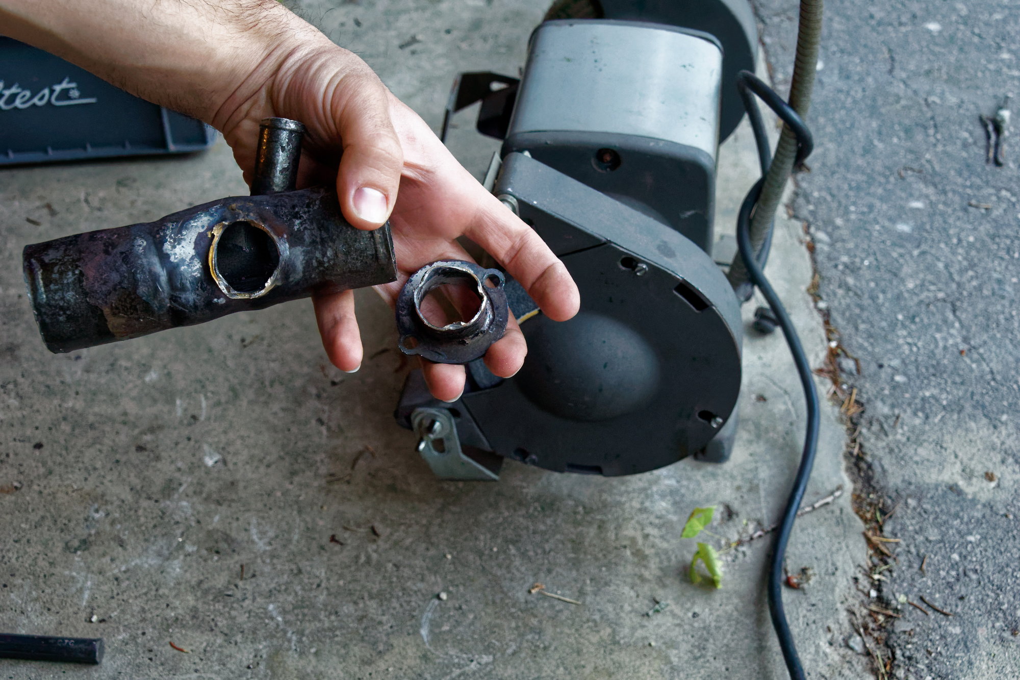
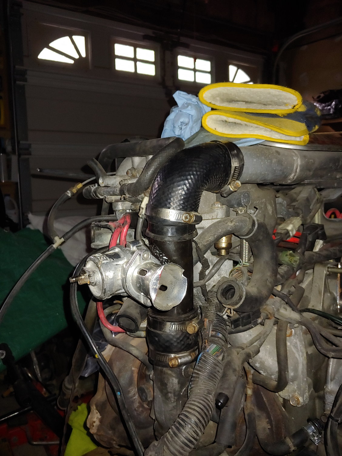
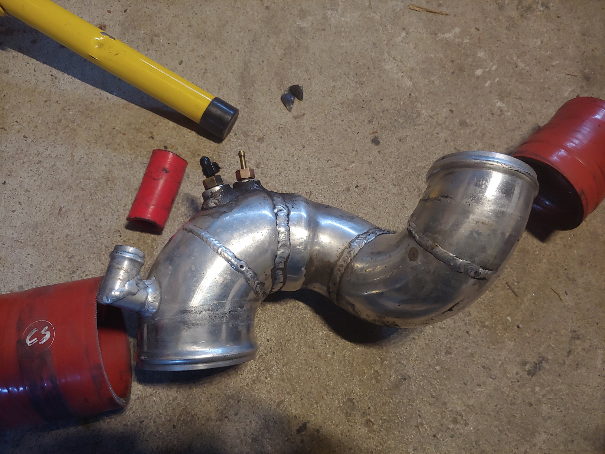
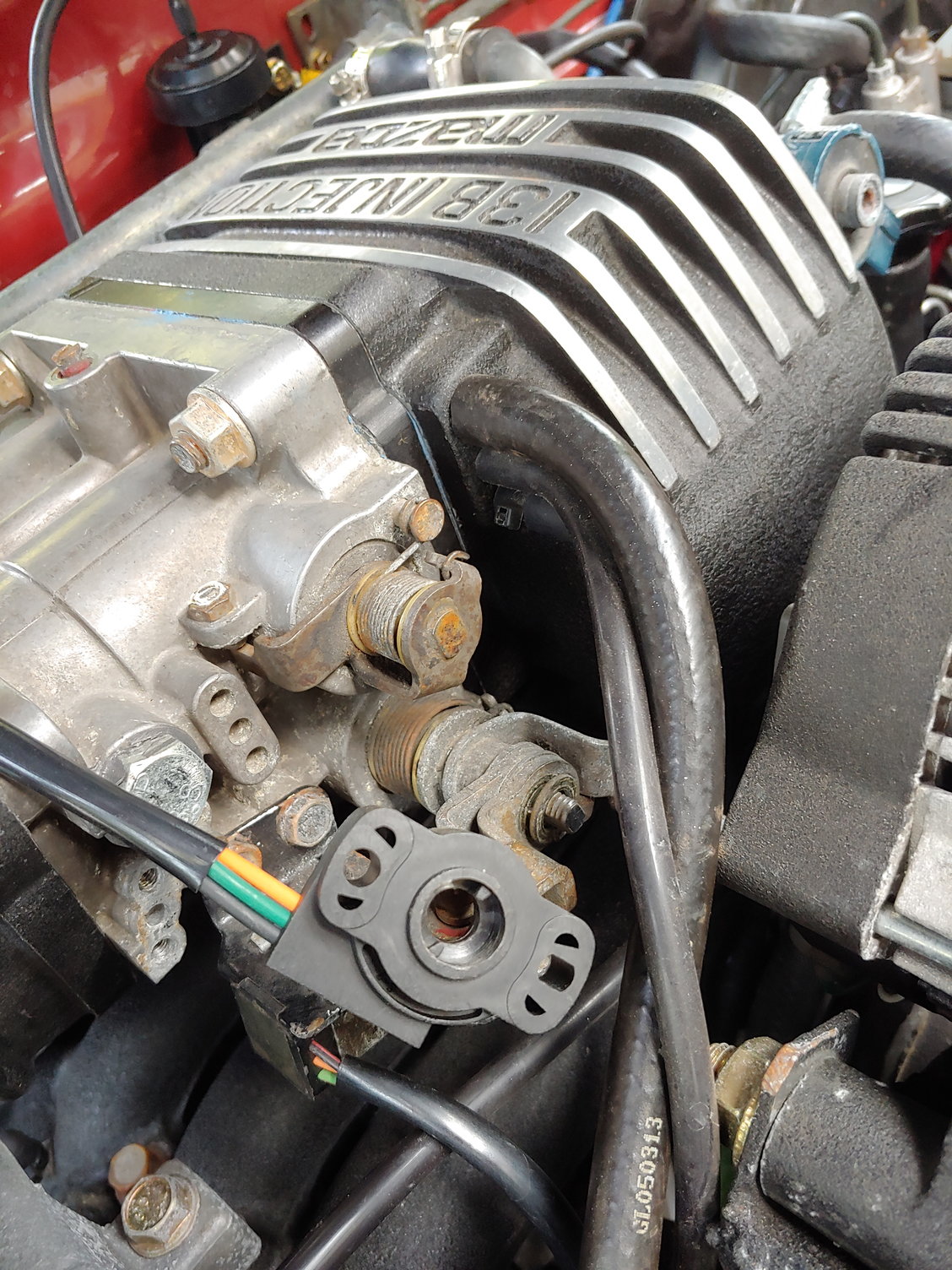
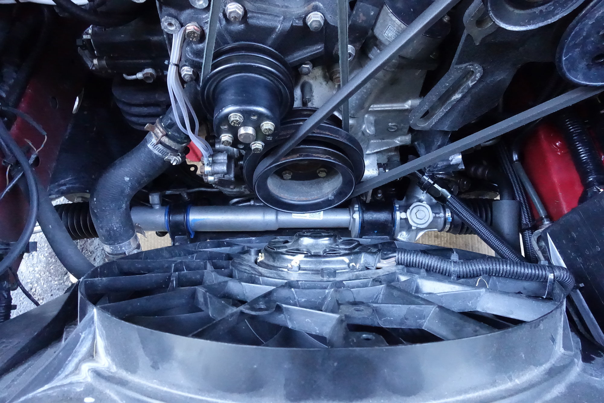
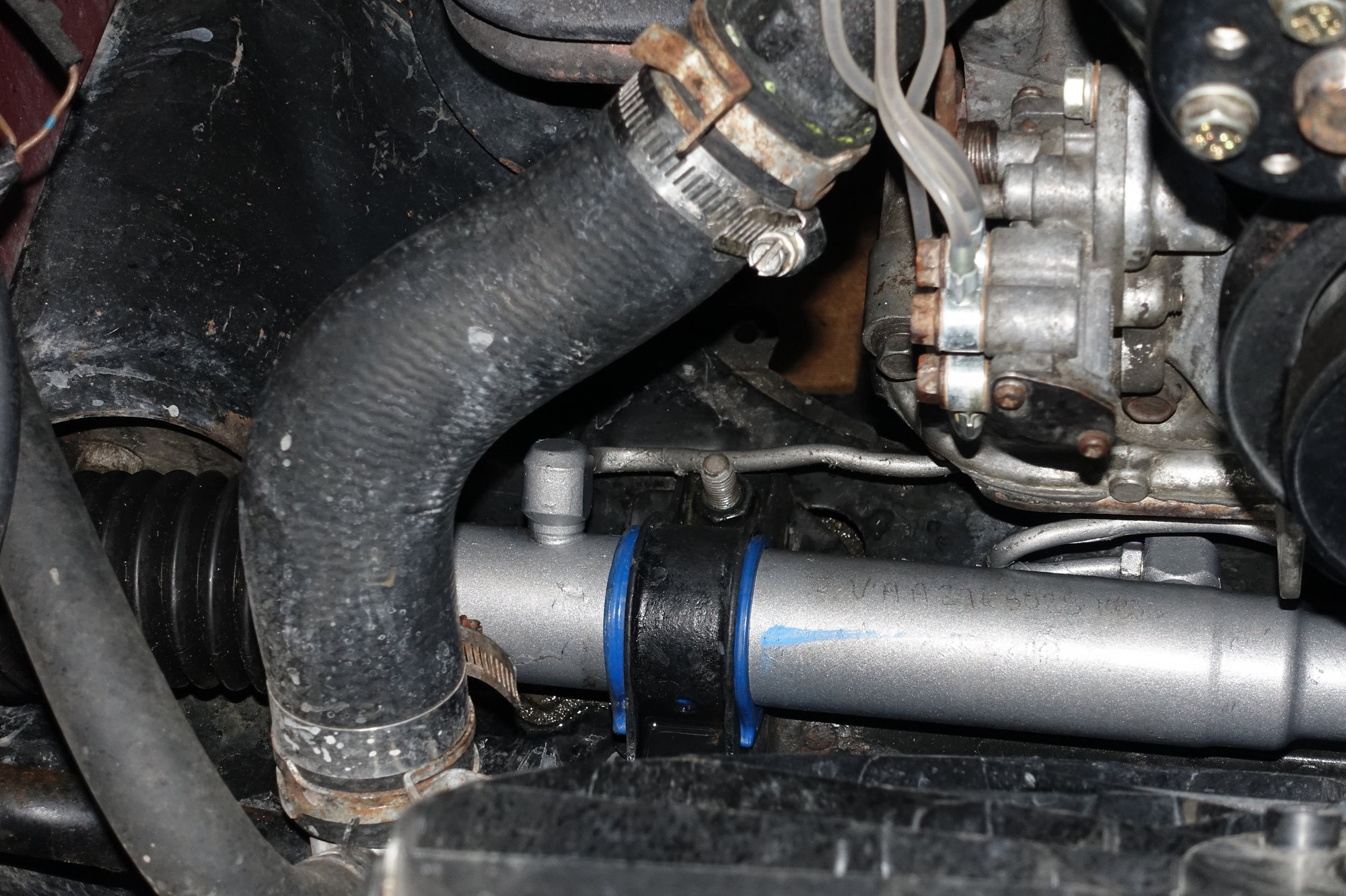
I think I have a photo of the car somewhere, but this car was absolutely ruined in the crash. It was hit so hard on the passenger's side front that the driver's side doorframe was skewed. How bad was it? The red paint on the blowoff valve:
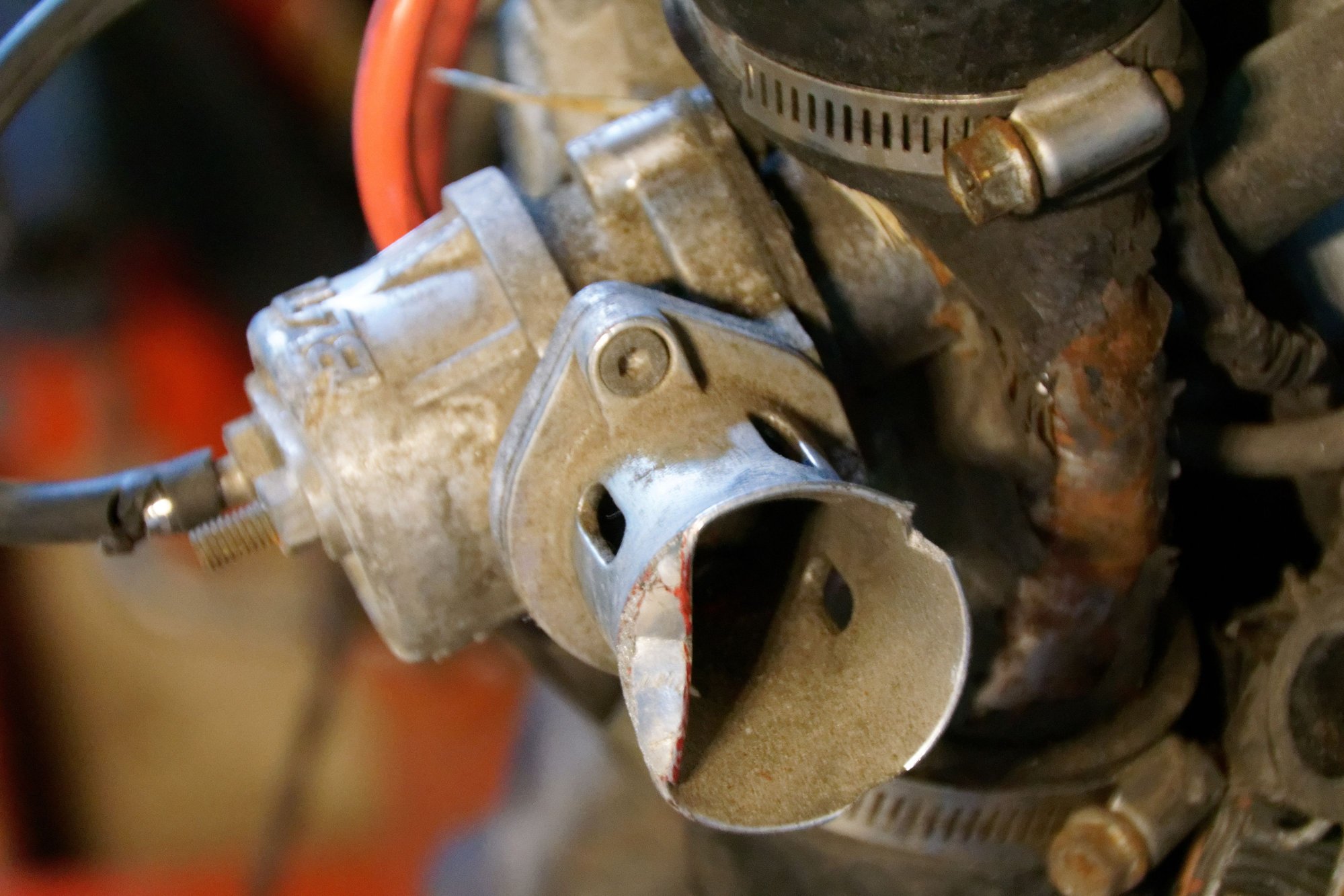
is from the shock tower hitting it. Meanwhile the tube got completely crunched inward:
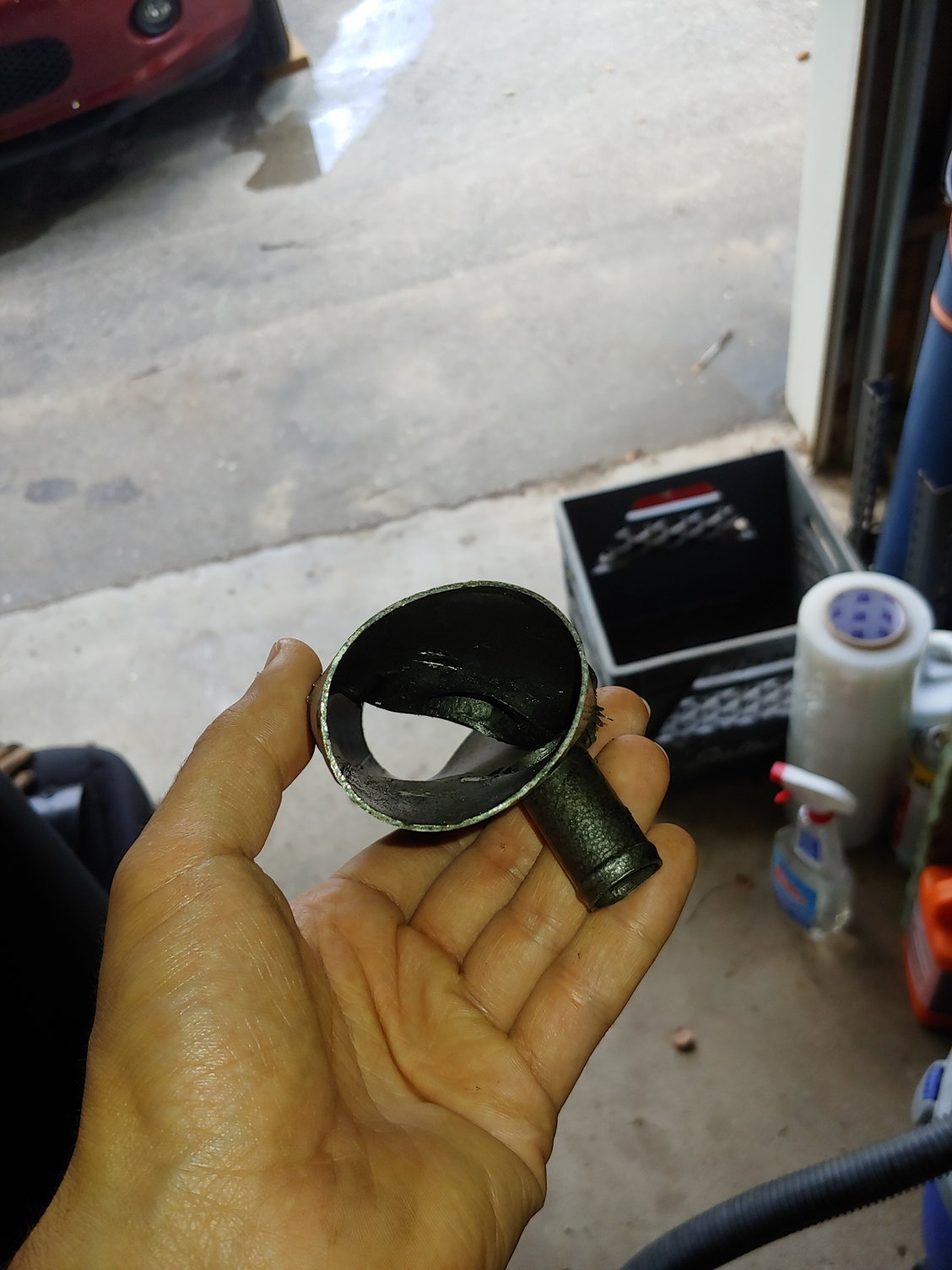
So that's going to need addressing. Even the intercooler was hit hard enough in the crash to snap the rivets from its bracket:
I can still use the intercooler as-is, but I have a S4 TII spare I could use too if it fits.
Anyways, that's about it for now. Until next time :)
This isn't much of an update, but I found a neat solution to a problem that's been bothering me. This is not a fix I recommend anyone trying, purely on the basis that it shouldn't be necessary. This is me changing a sensor calibration to compensate for a problem, not a mod that anyone should be doing on their own cars.
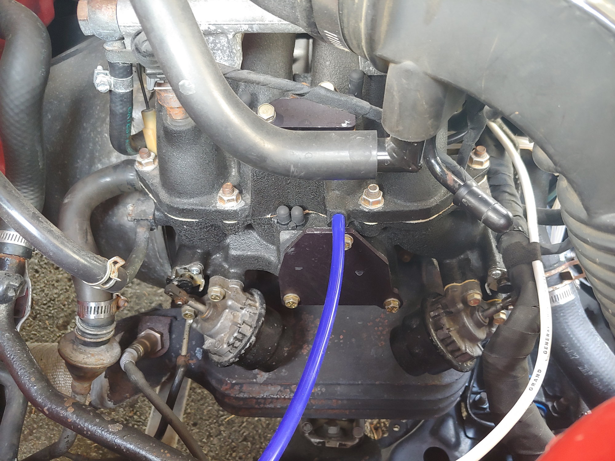
The hesitations I have been fighting on and off for awhile have come back with a vengeance, especially in the heat. I noticed that as it was getting hotter, my AFRs were appearing leaner. The logical assumption at this point would be a temperature sensor. However, I have checked them all and they all measure out fine. There are two intake air temp sensors and one coolant sensor (well, one that the ECU actually cares about for enrichment) and the readings were all normal. One weird thing was that AFRs at idle seemed about right (12.5 - 13.2), whereas under any load AFRs went >15, and at cruise AFRs were ~14. So this was something load dependent.
I also have no way to tune my ECU at all, and the stock FC ECU can't really measure it's own AFRs to compensate (or even throw a code, at least for S4s). A standalone is in the plans for my turbo swap, but until then I needed to find a way to richen the mixture. I figured the only way to do this was to mess with the MAF reading, similar to what an Apexi S-AFC would do. So that's what I did:
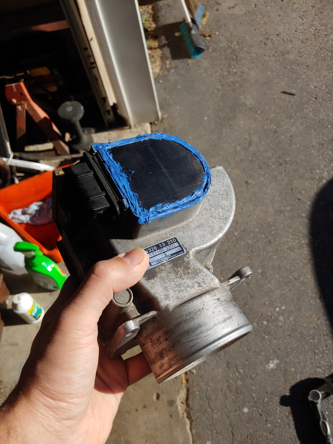
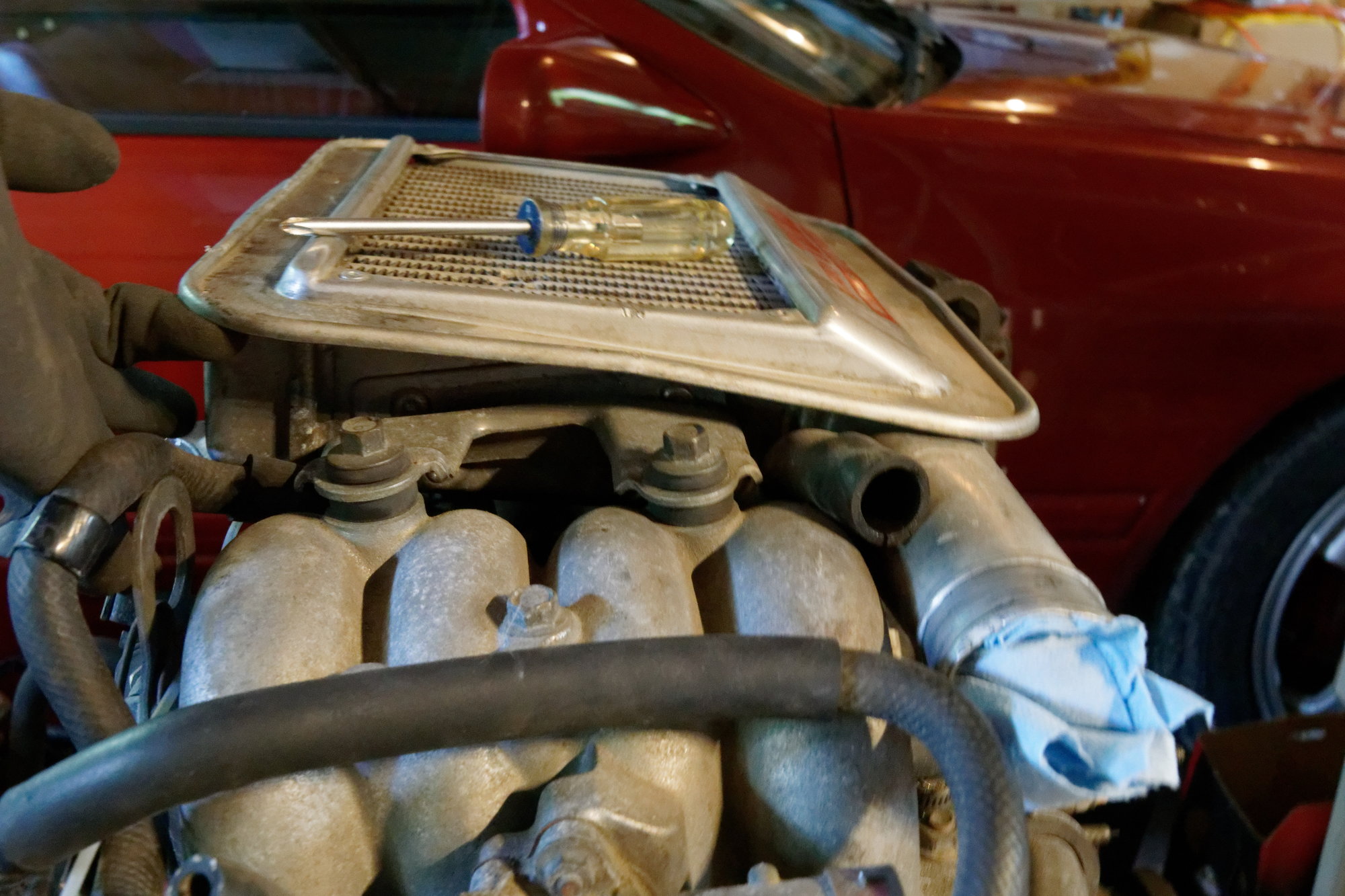
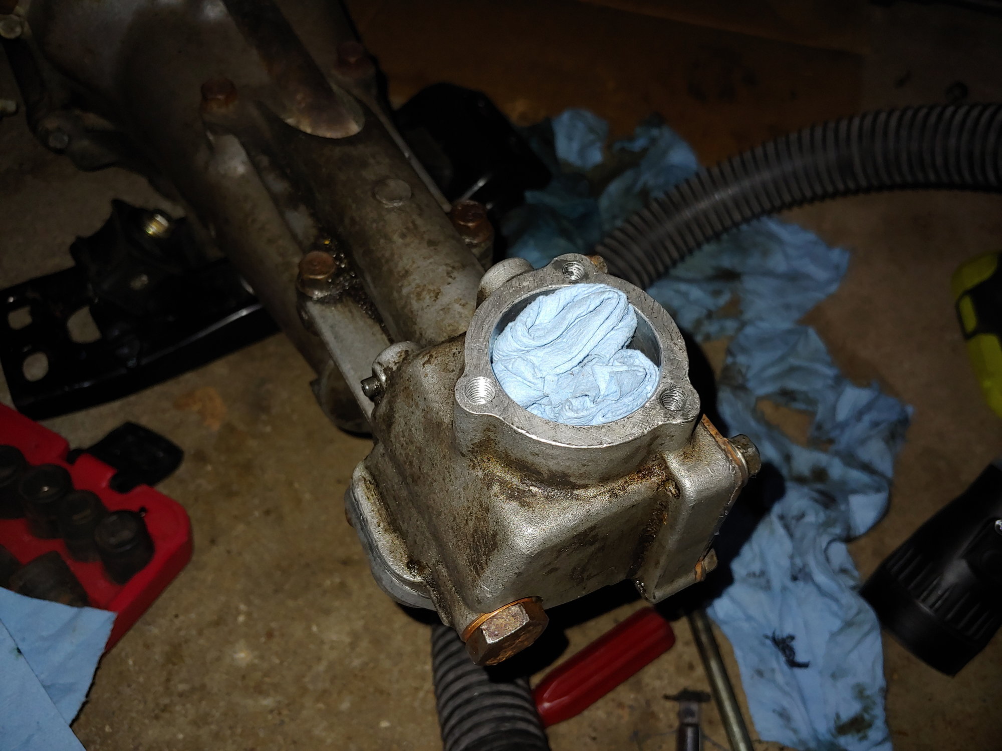
Removed the MAF sensor. The blue silicone is from the last time I removed that cover, to see if this one had been messed with (like my last one). At the time I found nothing unusual. After cutting the silicone and popping the cover off:
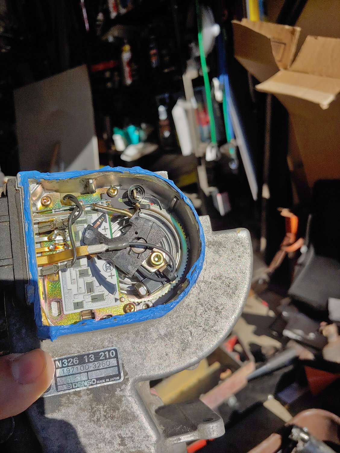
What I wanted to do was reduce the spring tension slightly on the MAF flapper door. The intuition is as follows:
Same volume of air can open door more easily => Door being more open tells the ECU that it is flowing more air => ECU meters fuel around the assumption that there is more air than there actually is => Richer mixture.
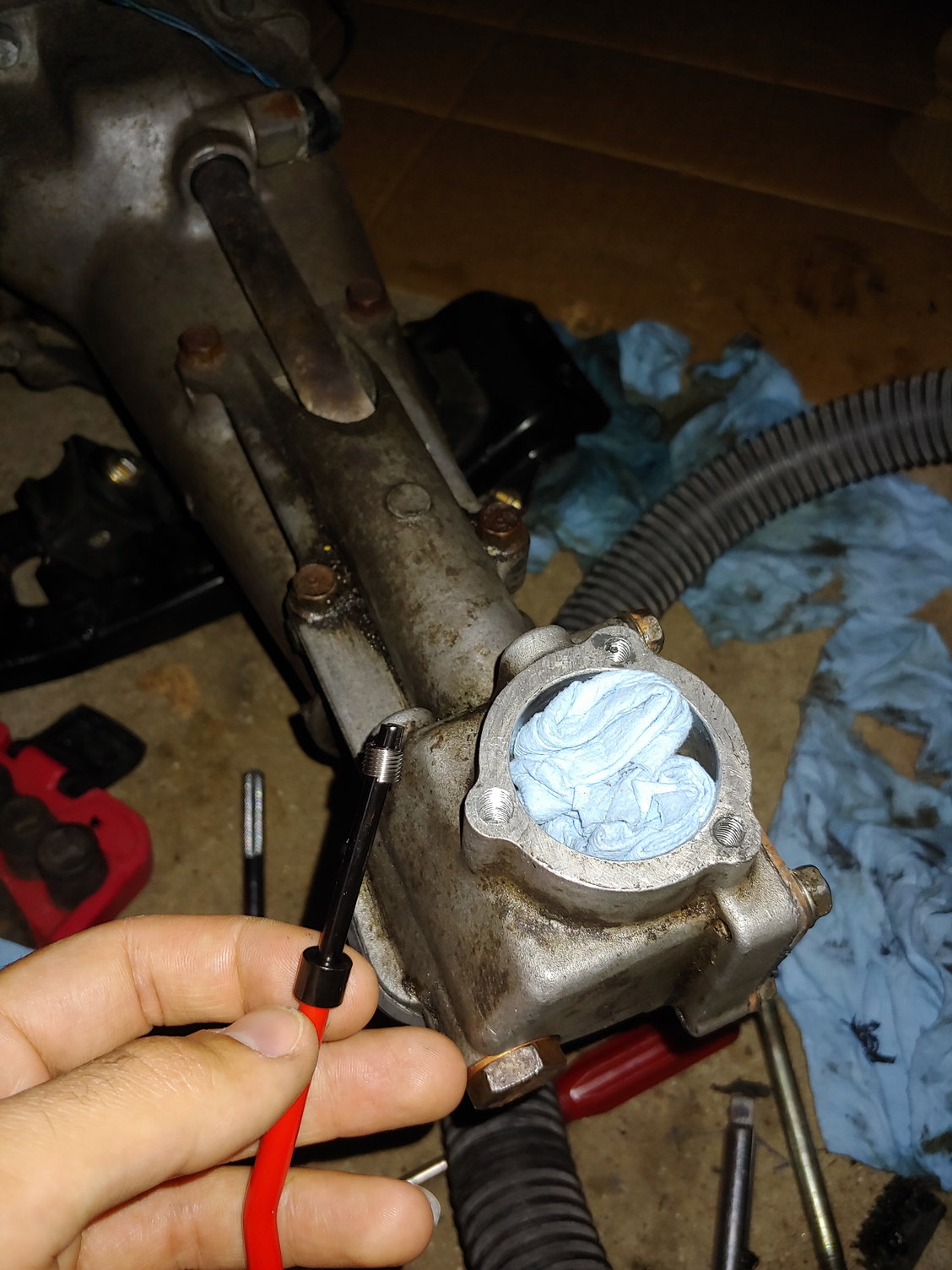
I did some searching and found others had done this (usually out of the erroneous assumption that more fuel = more power), but the pictures were long gone. Mazda actually made this very easy though. I used a bit of paint to mark the original position, then pushed that little tab away from the toothed wheel and rotated it a few notches. Then put the cap on and reassemble, and now the MAF will trick the ECU into richening the mixture.
My first attempt resulted in lots of popping, so I had gone too far. Moving a couple notches back had the hesitations come back. I settled somewhere in the middle, around four notches "richer" than the original position. Now the AFRs are about 13.5 when crusing, and 12.5-13 under acceleration. Idle AFRs are a bit fat at 11, but the MAF adjustment is global so I can't do anything about that other than use the trim pot Mazda put near the airbox. And even at "full lean", the idle trim resistor still only gets it to about 11.
So now what I've basically done is trade the hesitations for a slightly gassy idle, but it's a trade I would make 10x over. The car drives so much differently. It's way easier to take off at a lower rpm, it revs smoothly (although I can STILL feel the secondaries come online at 3800rpm), it free-revs way faster, and it accelerates much harder. I even had to learn to shift differently, since blipping the throttle now results in a much more immediate increase in RPM.
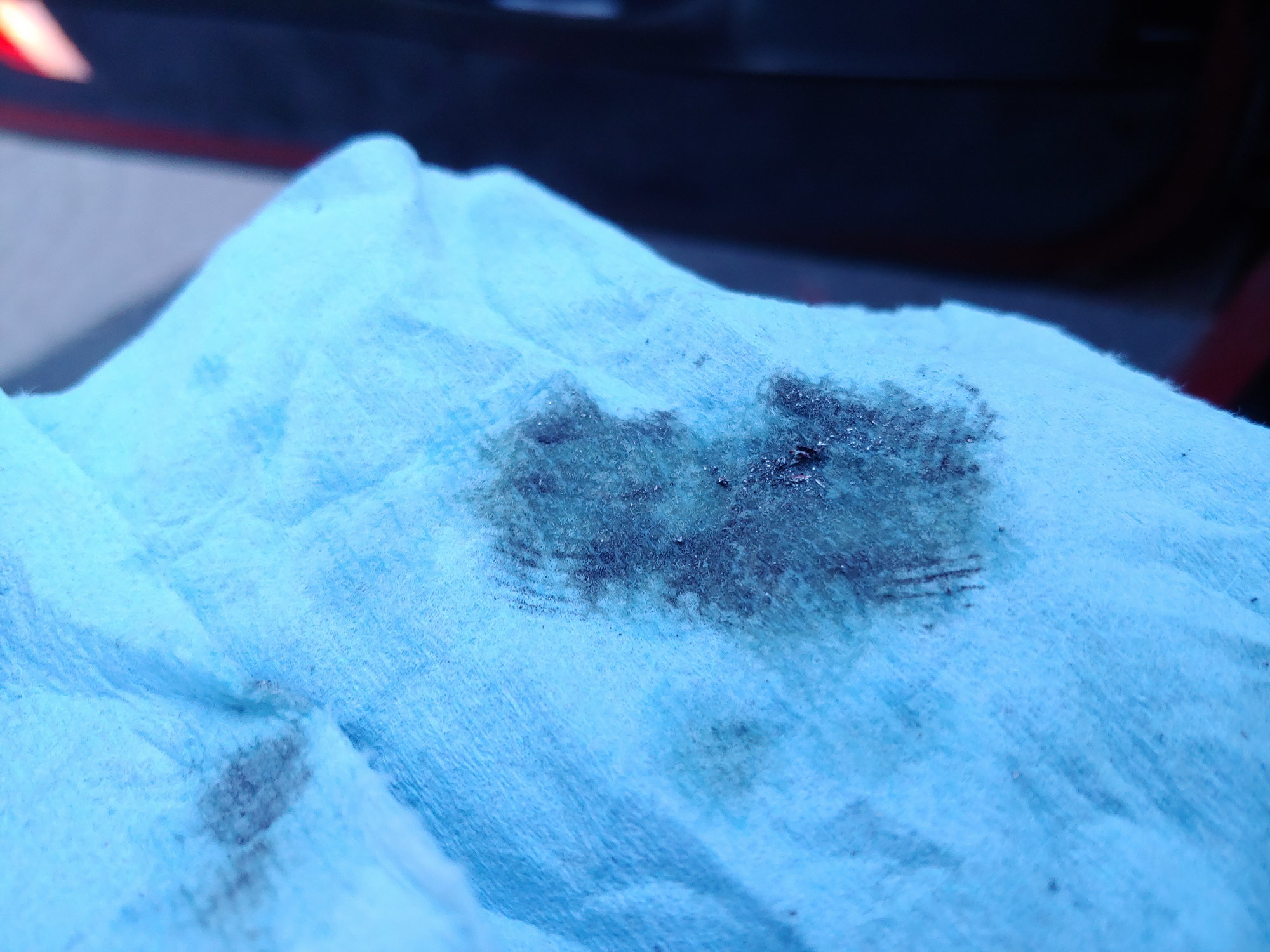
My personal theory on this is that the MAF itself is worn out. I don't know if this is the real cause, but I noticed a lot of scratching on the carbon trace underneath the wiper in the MAF. I'm wondering if the scratching can cause the resistance to change significantly, which causes the ECU to see less air than is actually flowing. This would be consistent with my symptoms, since at idle the AFRs were fine and the MAF isn't moving a lot around idle, hence receiving less wear on the carbon trace. When it was cold out in the winter / spring, I'm guessing the enrichment from the IAT sensor helped mask this issue.
Anyways, like I said it's not really an update. Once I have a standalone though I intend to run speed-density and just ditch the MAF altogether. It would be nice to be able to simply press a few keys on my laptop to alter AFRs, so I'm excited to have that tuning flexibility at my disposal. Also, took a picture freshly washed:
And that's about it for now. Until next time :)
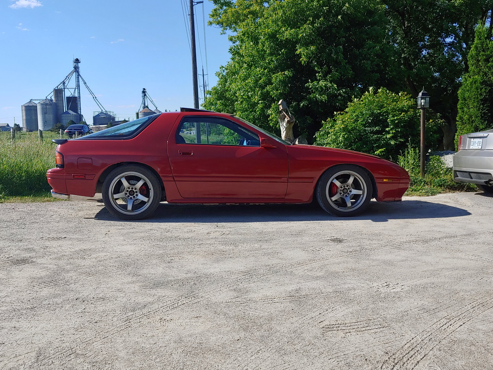
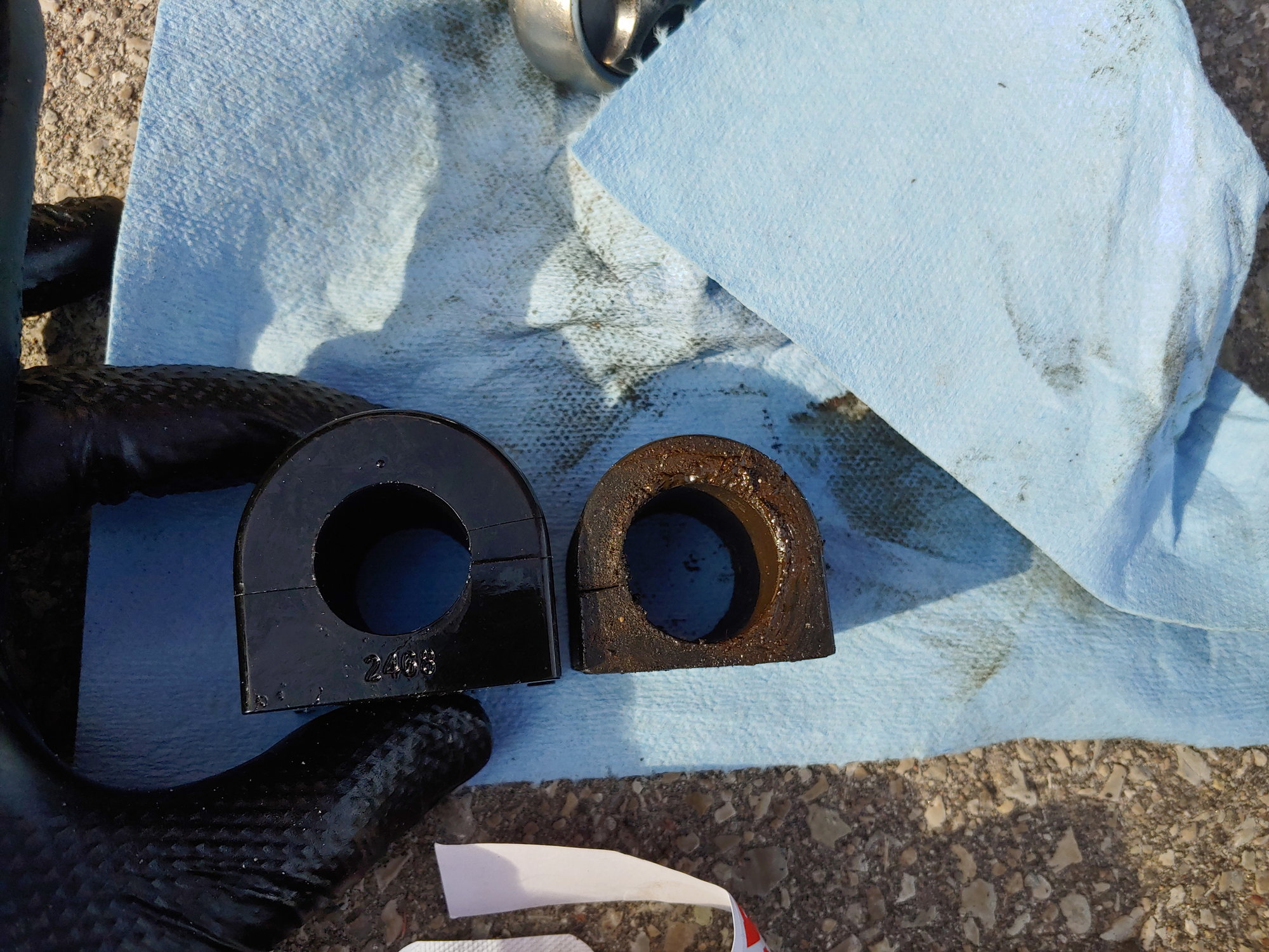
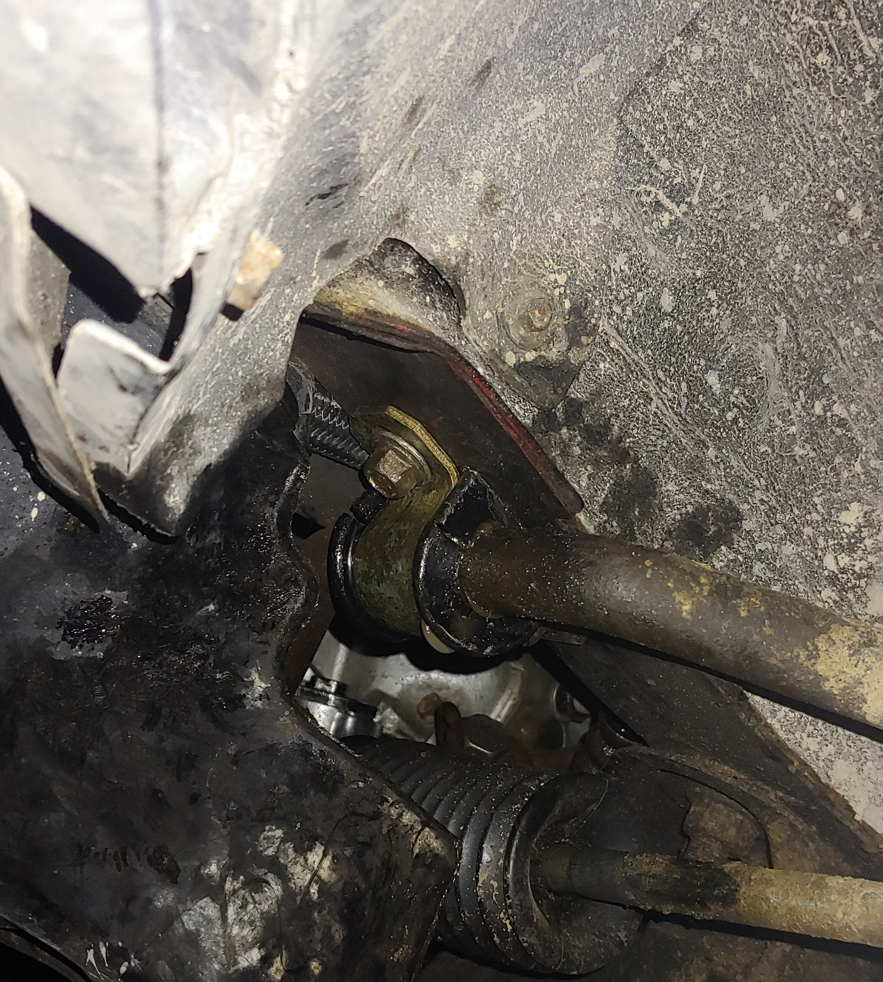
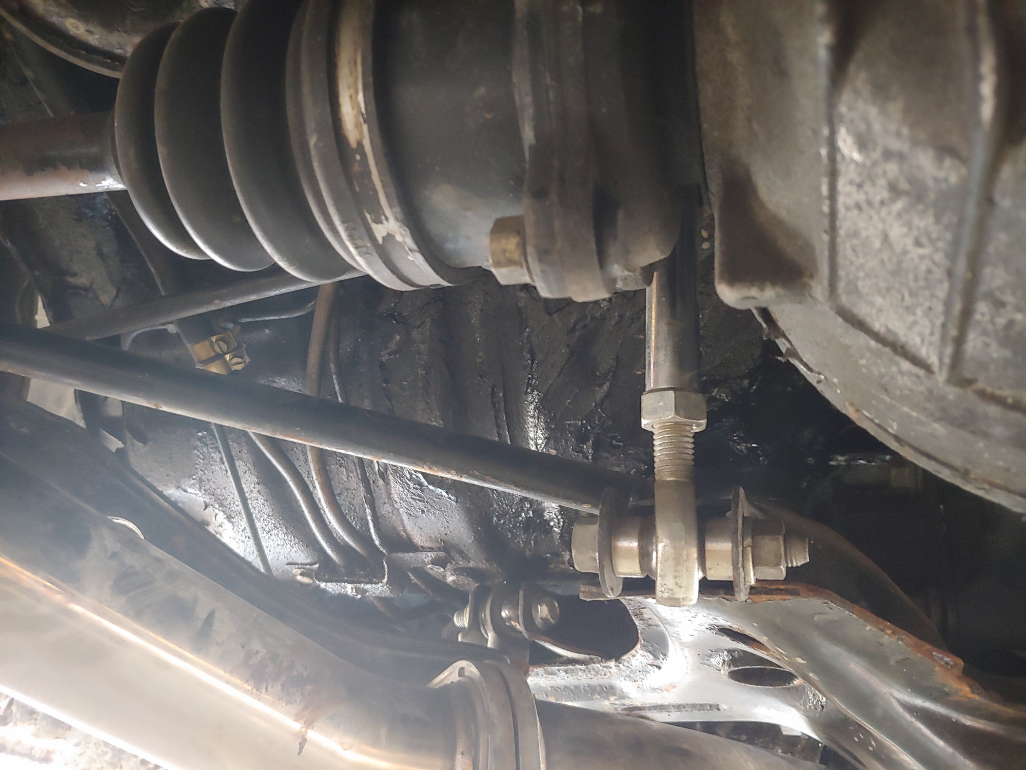
One more little fix I have been meaning to do for awhile is the front sway bar bushings. They were replaced a few years ago when I did a complete polyurethane bushing swap. But there's a bit of a problem:
They're too big. I think what's happening here is that "base" models like mine got a smaller 22mm bar, whereas Turbo cars got a 24mm bar. I'm guessing this isn't so much an NA / Turbo difference as a 4 lug / 5 lug difference, but all the references I found say that it's Turbo IIs that got the bigger bar, so we'll go with that for now. I also say "base" in quotations since I still have no idea what spec my car was from the factory. My car lacks the original harness for the rear wiper, which according to the Mazda factory manual qualifies mine as a "low grade" model. Base '86 models had no sunroof, but mine has a sunroof. Meanwhile mine did not have the power steering or AC from the factory as indicated by one of the info sheets I have from the original purchase. The car came with no side decals (still has none), but the original sheet says "GX". Then Canadian models had slightly different options from US models anyways, so who knows.
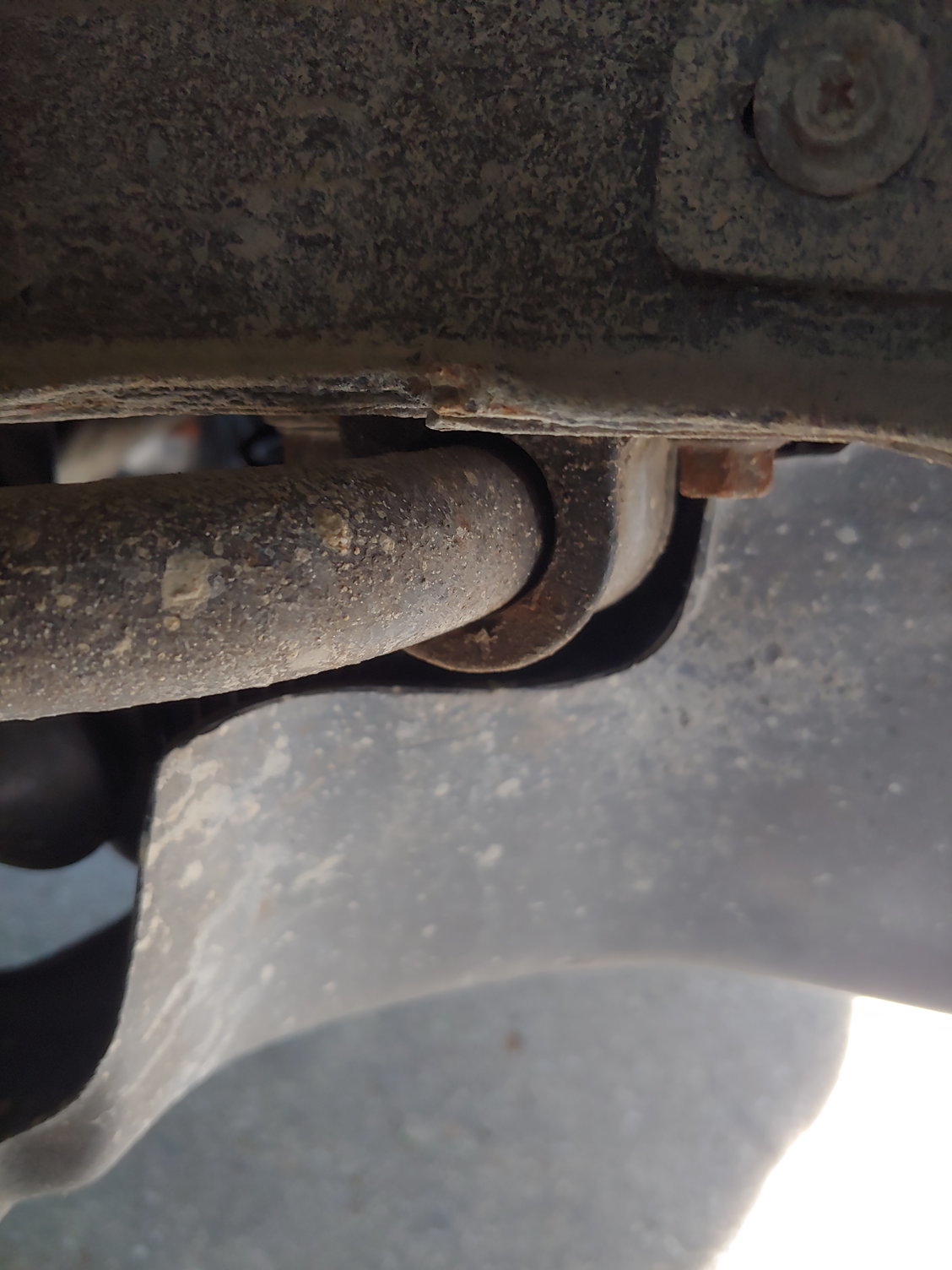
This presented a bit of an issue finding a new bushing, since the Energy Suspension kit clearly comes with the 24mm one. I don't want to get OEM ones since they're rubber. So I went and found some generic 22mm sway bar bushings, and Amazon had them at my door two days later. Removing the old ones only took 5 minutes, so here's the comparison:
About 2mm wider in the direction parallel to the bar.
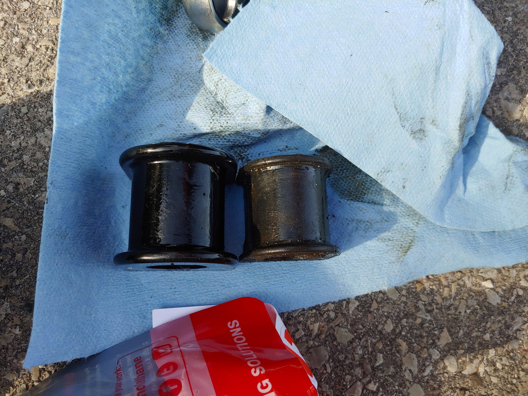
Also 2mm wider in forward / back direction. This looked like an issue, but the bracket actually fit okay.
And then it's about 4mm taller, which will turn out to be an issue for fitment. After installing, see the following:
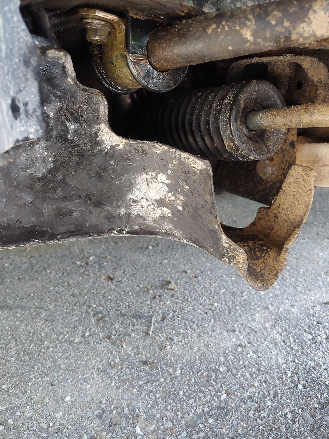
There's no binding so it's okay for a couple test-drives, but I'm going to have to pull it back out and cut the excess from the bottom of the bushing. Luckily it's a flat side, so it shouldn't be too difficult to cut down the 4mm and reinstall.
After that I found that the rear-passenger side tire was low at 20psi. I guess I have another bead leak, so I'll have to bring that to a shop and get it sealed. At least it'll match the bead sealant on the driver's side rear now.
The single biggest difference I have made to the handling though (bigger than the bushings even) was the MAF fix. I tested this out before the above repairs, so I can say this with certainty; The whole car feels entirely different. Since the rear of the car responds so much throttle inputs, the entire car is faster now. Not just in a straight-line but even through a corner since the new throttle-response and acceleration changes how the car handles. The car is quieter, there's less NVH from the drivetrain, and if I'm not paying attention I suddenly find myself speeding. As much as the hesitations felt occasional it's clear I was down on power at all rpm. I already loved the car (obviously) even with the occasional hesitations, but now driving the car is sublime.
It's weird, screwing around with the MAF sensor calibration is without a doubt the single best thing I have done to this car. All it did is help restore lost power, and it's a night and day difference.
While I accumulate funds and parts for the Turbo swap, it's nice that I've finally fixed the biggest issue with the car. Until next time :)
You could look at just throwing some washers underneath the sway bar bushing clamps as well rather than trying to cut down the poly bushings.
adam525i said:
You could look at just throwing some washers underneath the sway bar bushing clamps as well rather than trying to cut down the poly bushings.
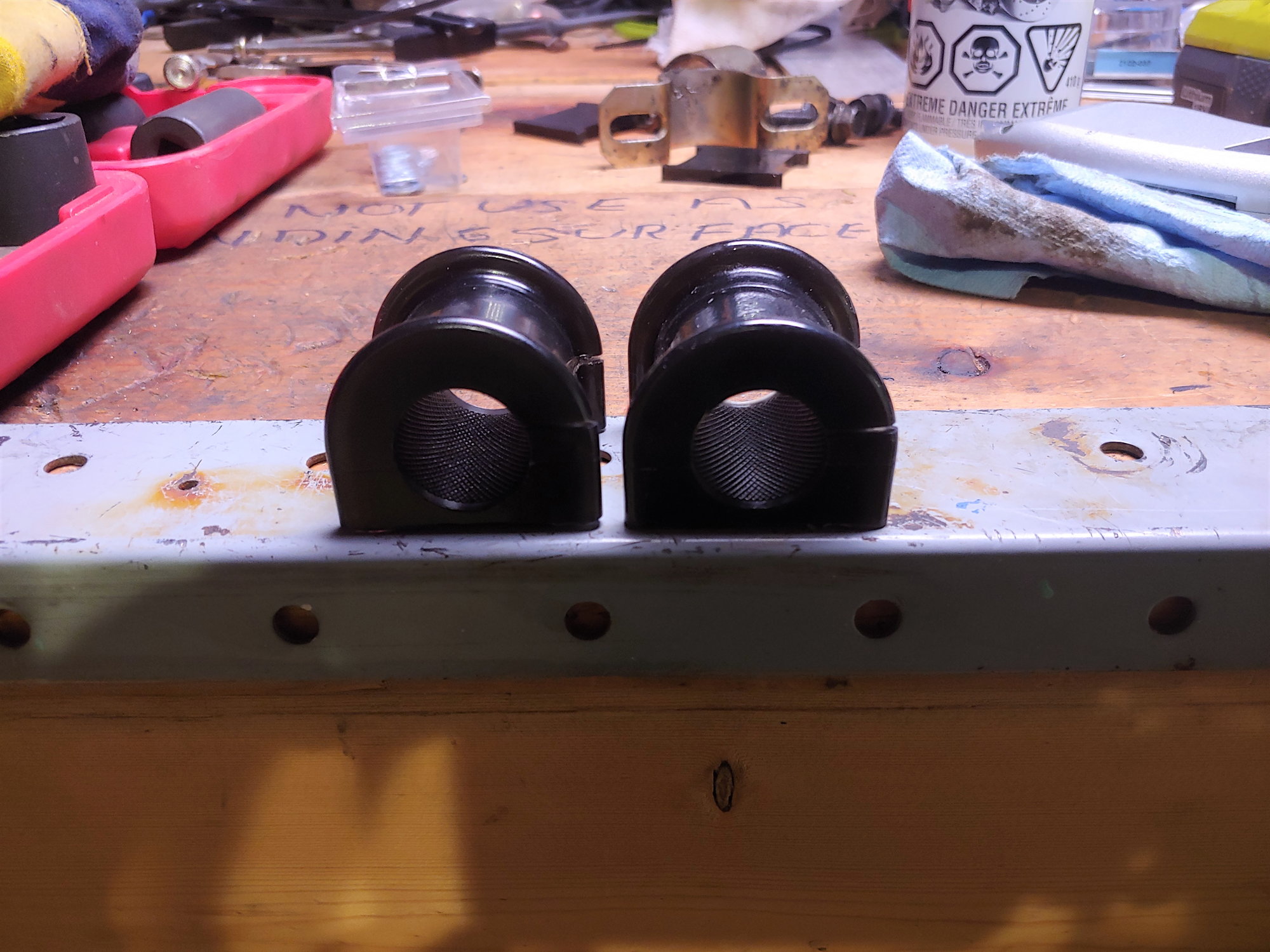
I did consider that, but the local Canadian Tire didn't have the appropriate size. Plus cutting the bushings was not too challenging. It only took about 5 minutes per:
The hardest part was keeping the cut at a consistent height. I didn't have a good way of doing it in one slice, so I had to carefully keep the razor blade parallel while working my way around the outside. I probably spent twice as much time cleaning and chasing the gunk out of threads:
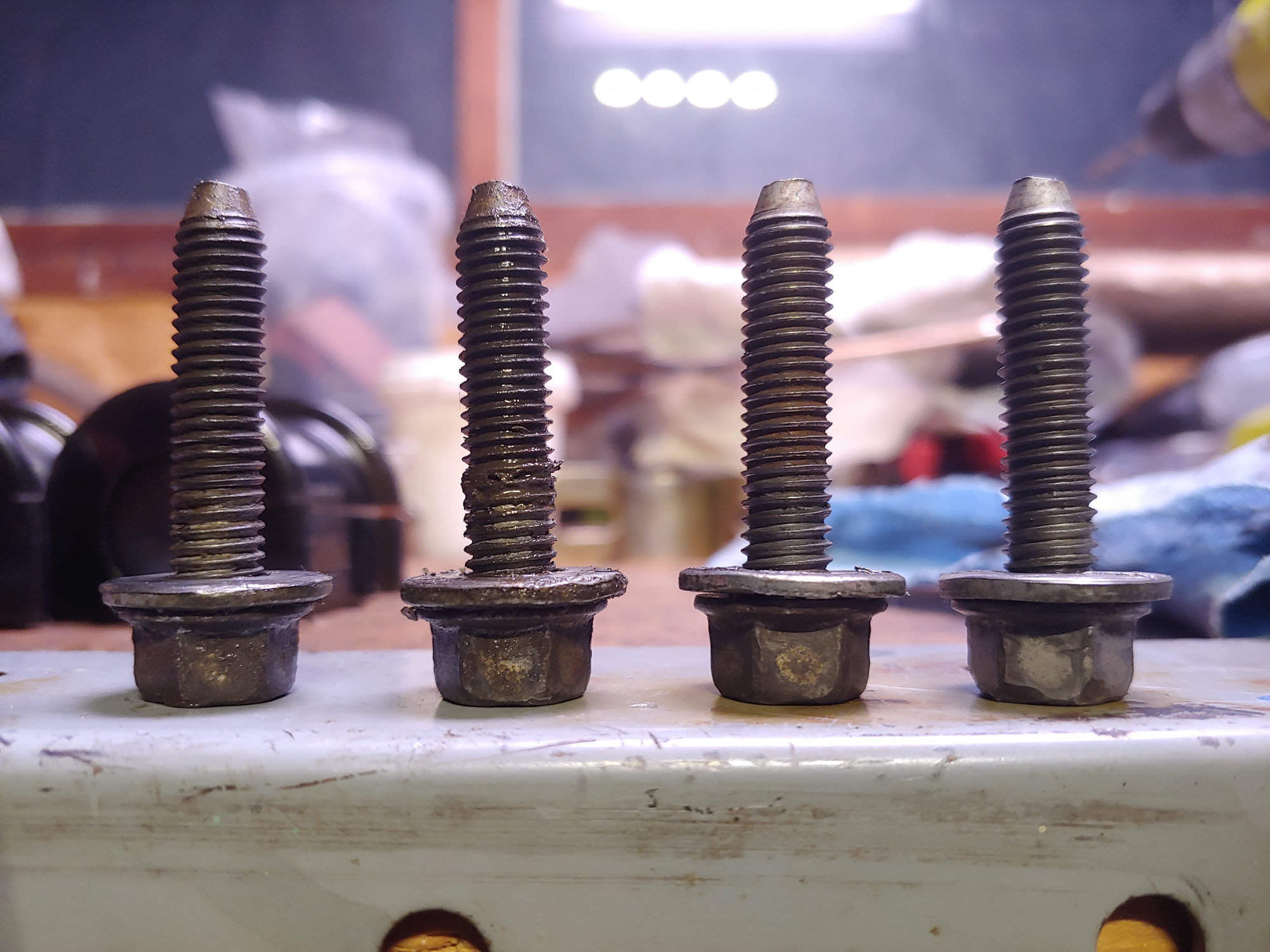
Cleaned on right, of course. It's not strictly necessary, but all fasteners on this car when I purchased were either rusted, crossed, or loose. I try to take the extra time and give the threads some love. Then I put it back together with Energy Suspension grease. The stuff that came with the bushings was O.K, but I find the Energy stuff has more staying power:
A much better fit. I may end up installing aftermarket sway bars in the future, but I know most of them differ from the stock size. I really want to get everything 100% dialed in on the current suspension setup before I try adding under / over steer, so that's not happening for awhile.
Until next time :)
The BOV and tube that came with my TII engine were crushed pretty hard when the car they came from was wrecked. I posted photos above. Now I mentioned possibly wanting to go back to the stock recirc valve, but that also necessitates finding the stock tube from the turbo to the intercooler. Then I have to get the valve itself and I really didn't want to add to the list of parts I have to chase.
There was an identical Blitz BOV (including the tube!) on eBay, but it sold while it was still in my watchlist. Also at $200, it wasn't exactly cheap. So for now I decided to fix what I have:
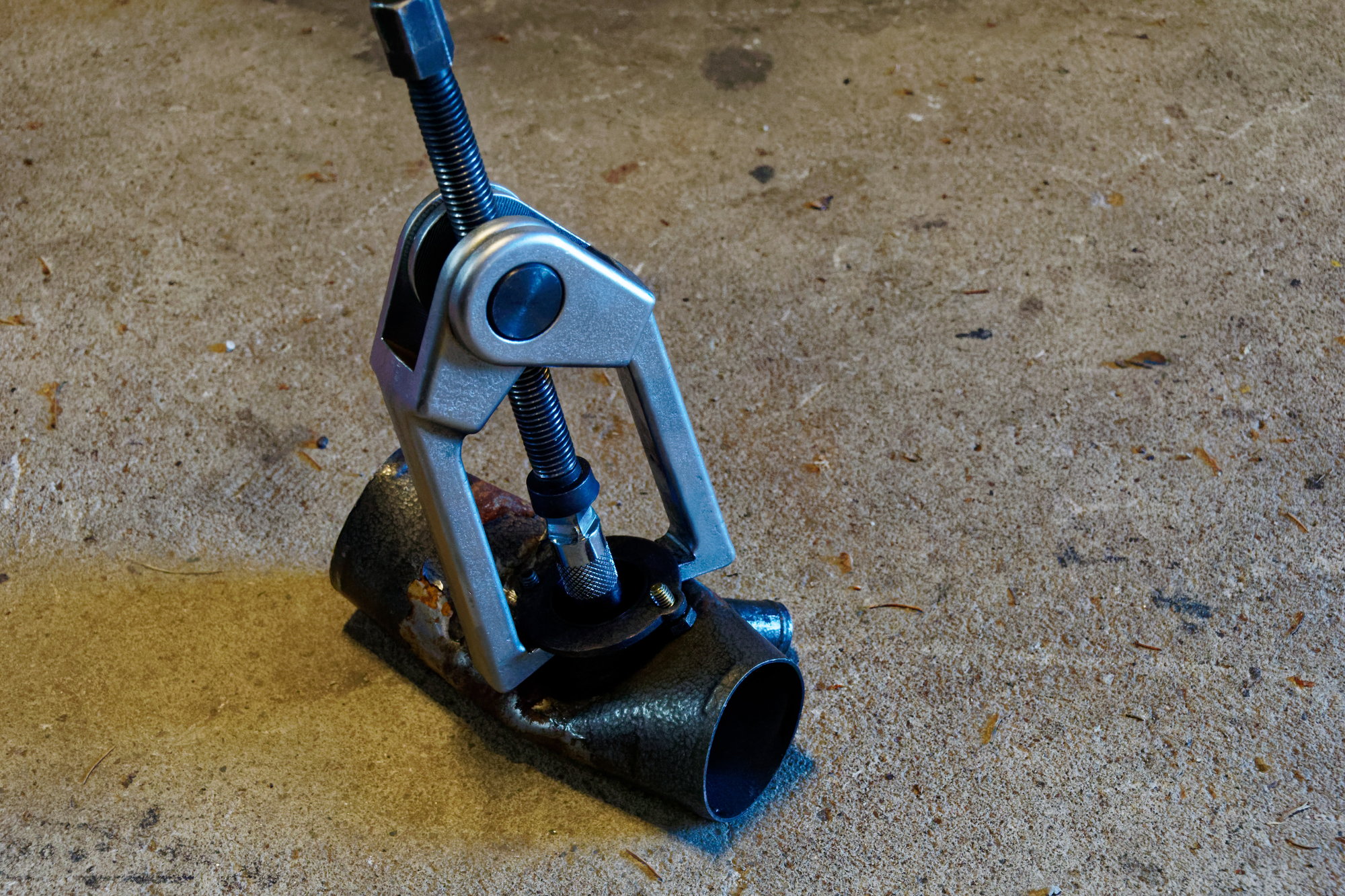
Used lots of heat and a puller to pull the biggest of the dents out of the tube. It was a bit challenging, but if you strategically heat the parts of the tube you want to flex, you can slowly pull it apart with minimal damage. "Minimal" however, includes the fitting for the BOV peeling from the body of the tube. Apparently it was brazed on. I used a chisel and a file to separate it completely:
Then ground away all the bronze and pounded the tube round again:
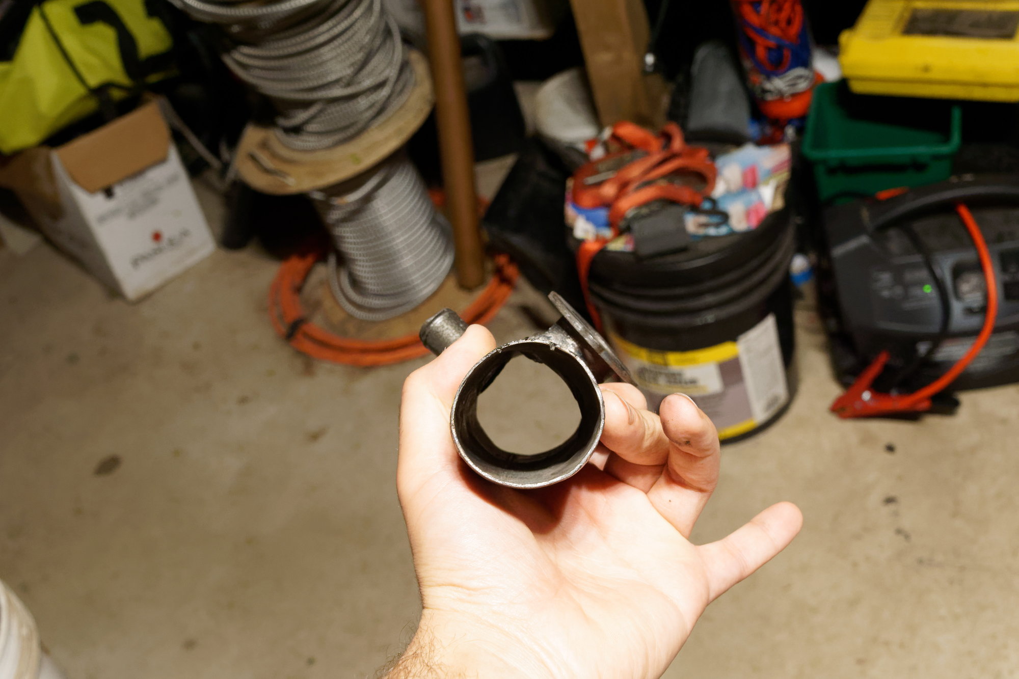
Round enough to seal, anyways. Then into the electrolysis bath to remove any rust:
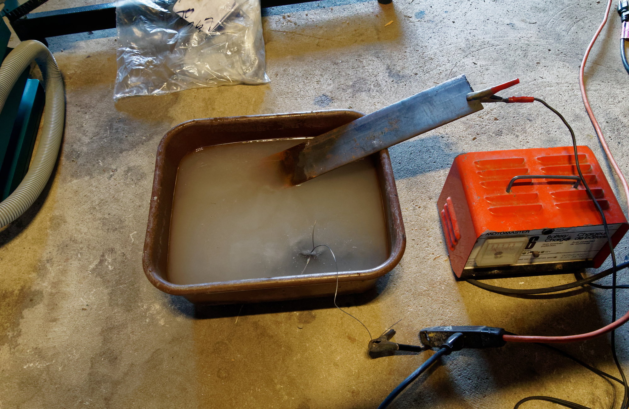
After that I used a wire brush to clean the inside of the tube. Tedious work, but for some reason Blitz decided the inside should be painted (?) and all the heat from welding had compromised it. Had to scrub it all out. Then it got a coat of engine enamel, baked in, and installed:
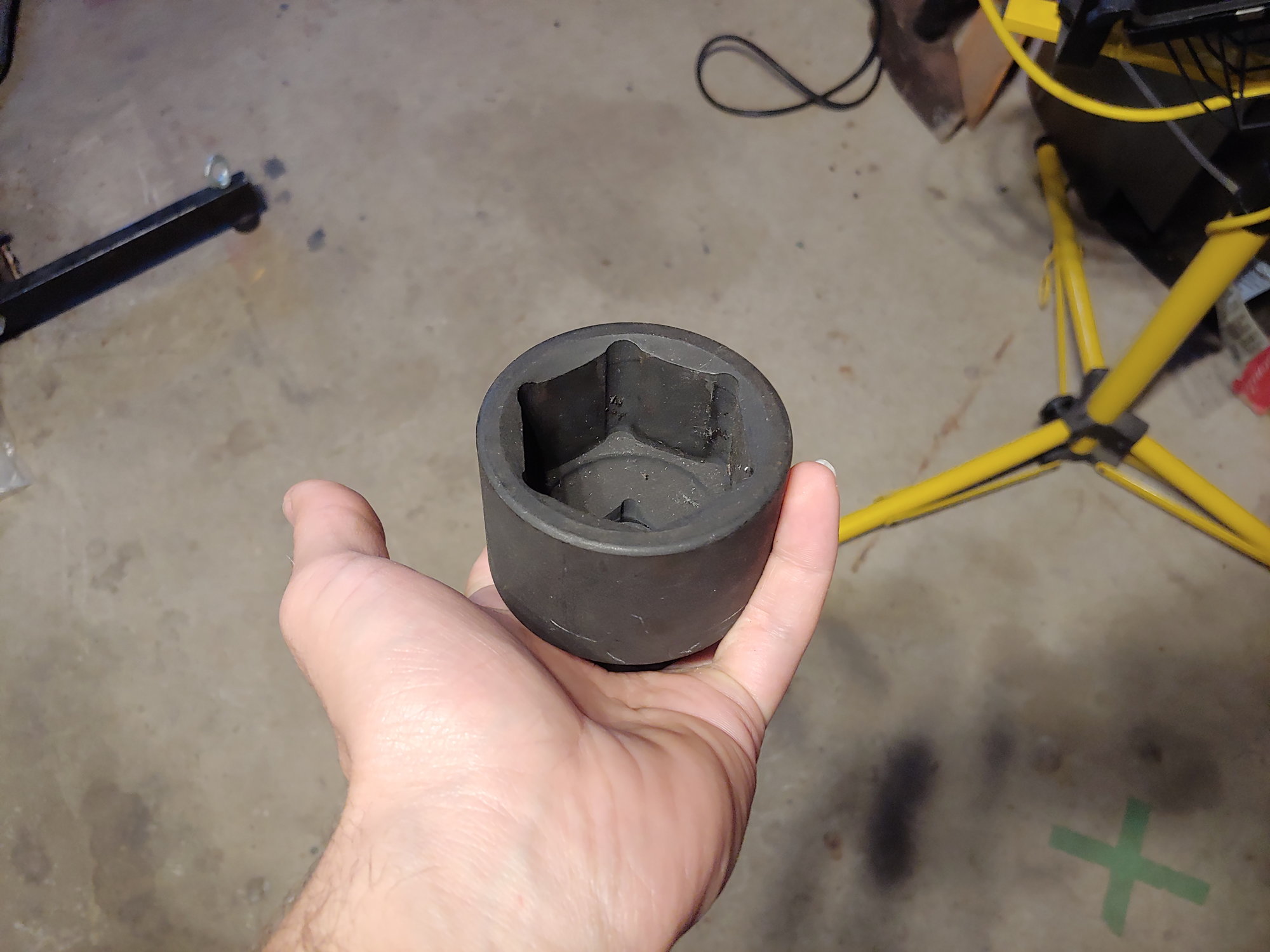
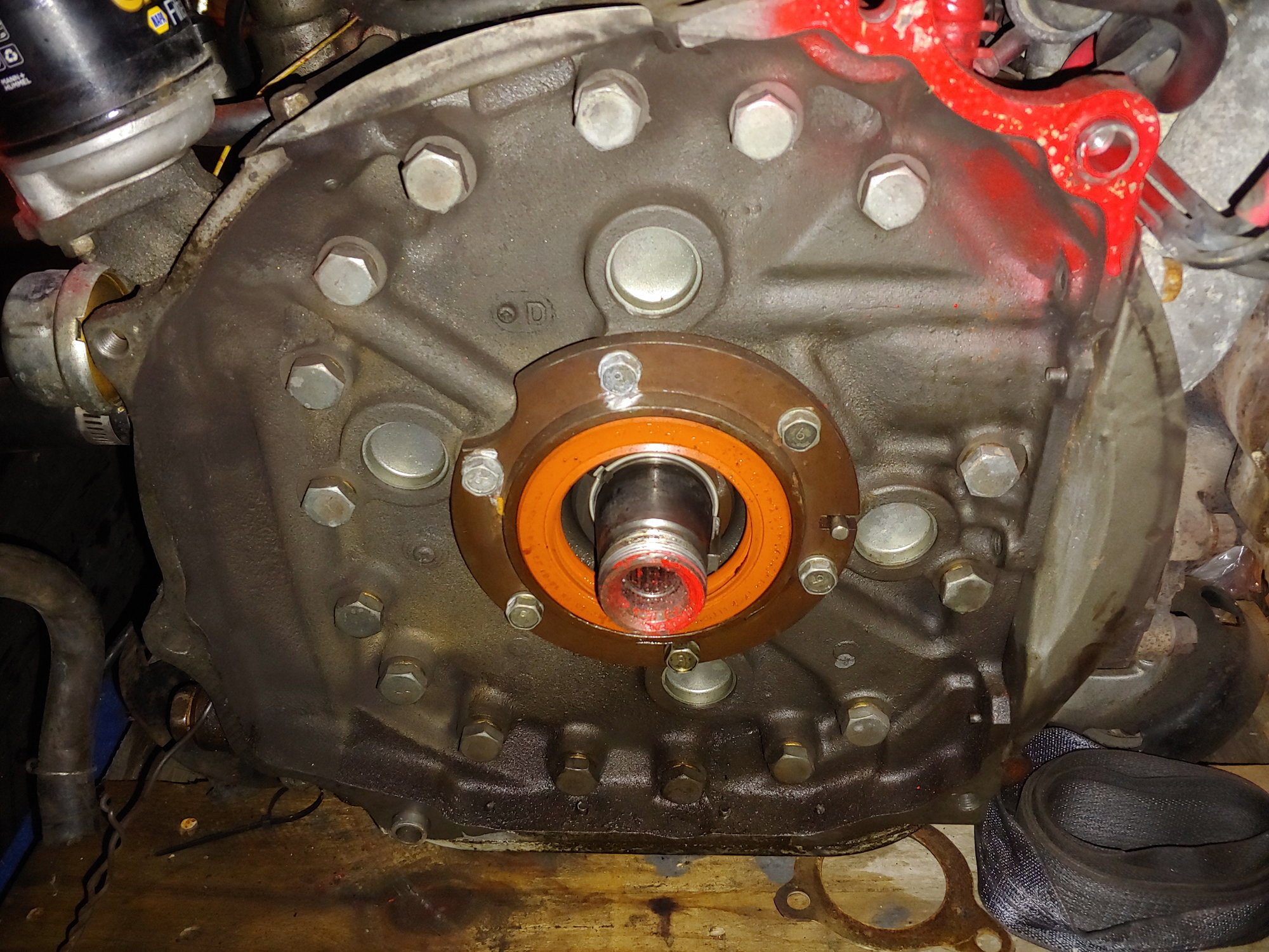
Ugly, but it should be functional. Long term I want to find a different solution. In the meantime this will let me aim my wallet at other parts. Speaking of which, I pulled the flywheel for resurfacing. A lightweight aftermarket unit would be nice one day, but the stock one is fine for now. Pulled out the ludicrous 54mm flywheel socket and impacted it off. The electric impact wasn't enough, but the pneumatic made quick work of it:
Local transmission shop did it for $80, and only three hours turnaround:
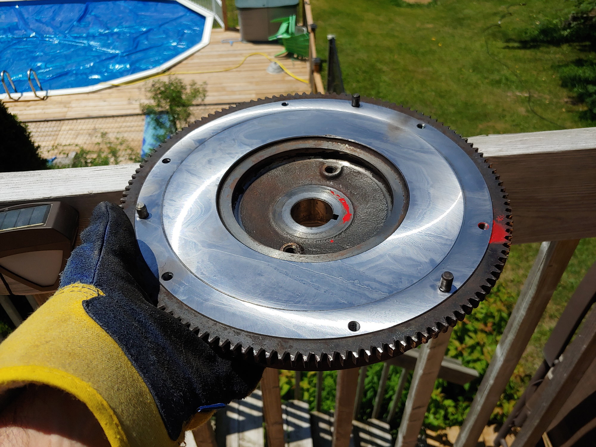
Nice and clean under here. Beautiful zinc coating on all the freeze plugs. A slight leak from the rear main, but I was going to replace that as a precaution anyways:
That's it for now. Expecting another part in the mail shortly.
Until next time :)
Today I used my Rx7 to go to a local path for a bike ride. The hatch is just big enough for a folding bike (or whatever these things are called, it doesn't really fold):
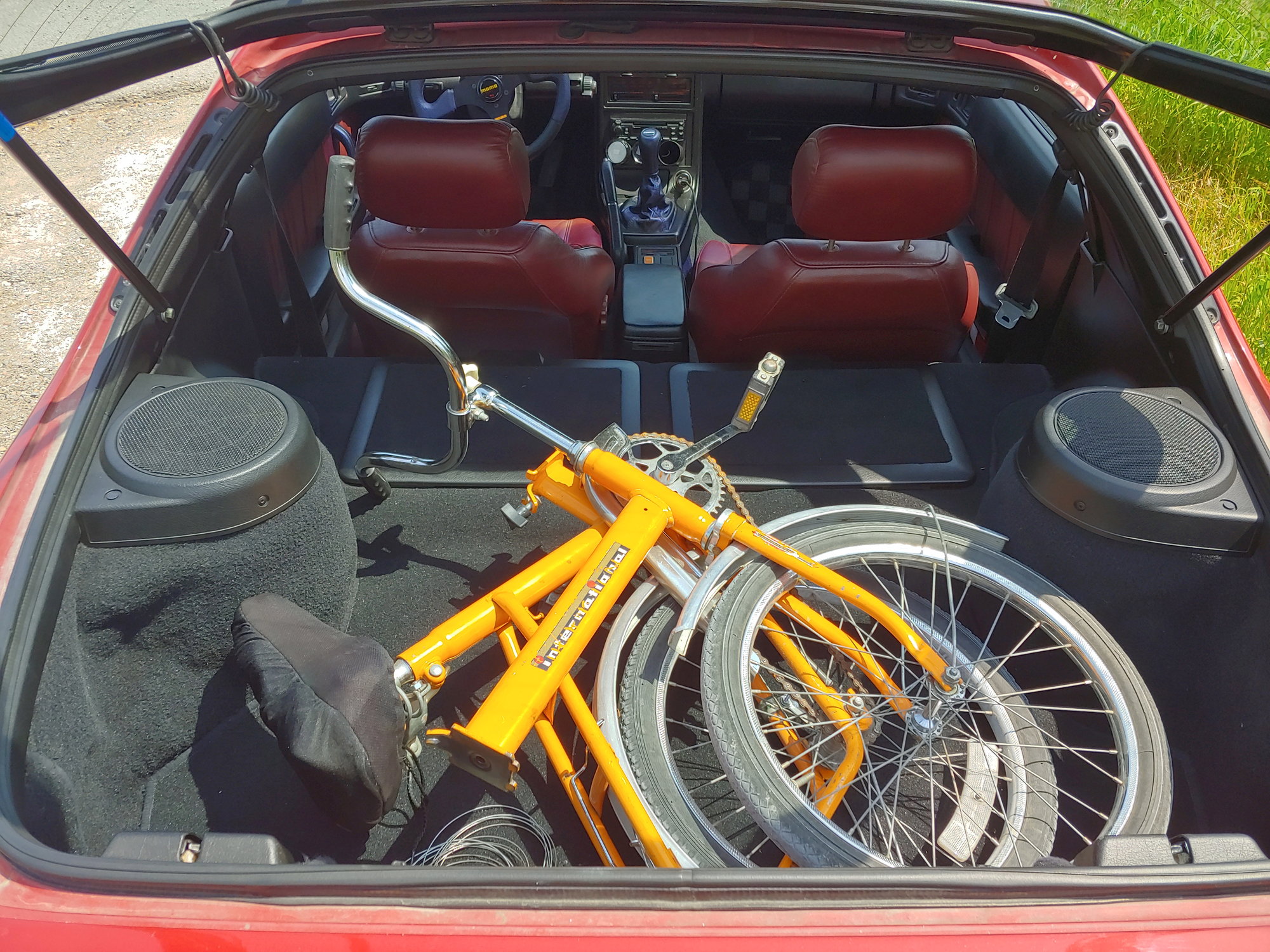
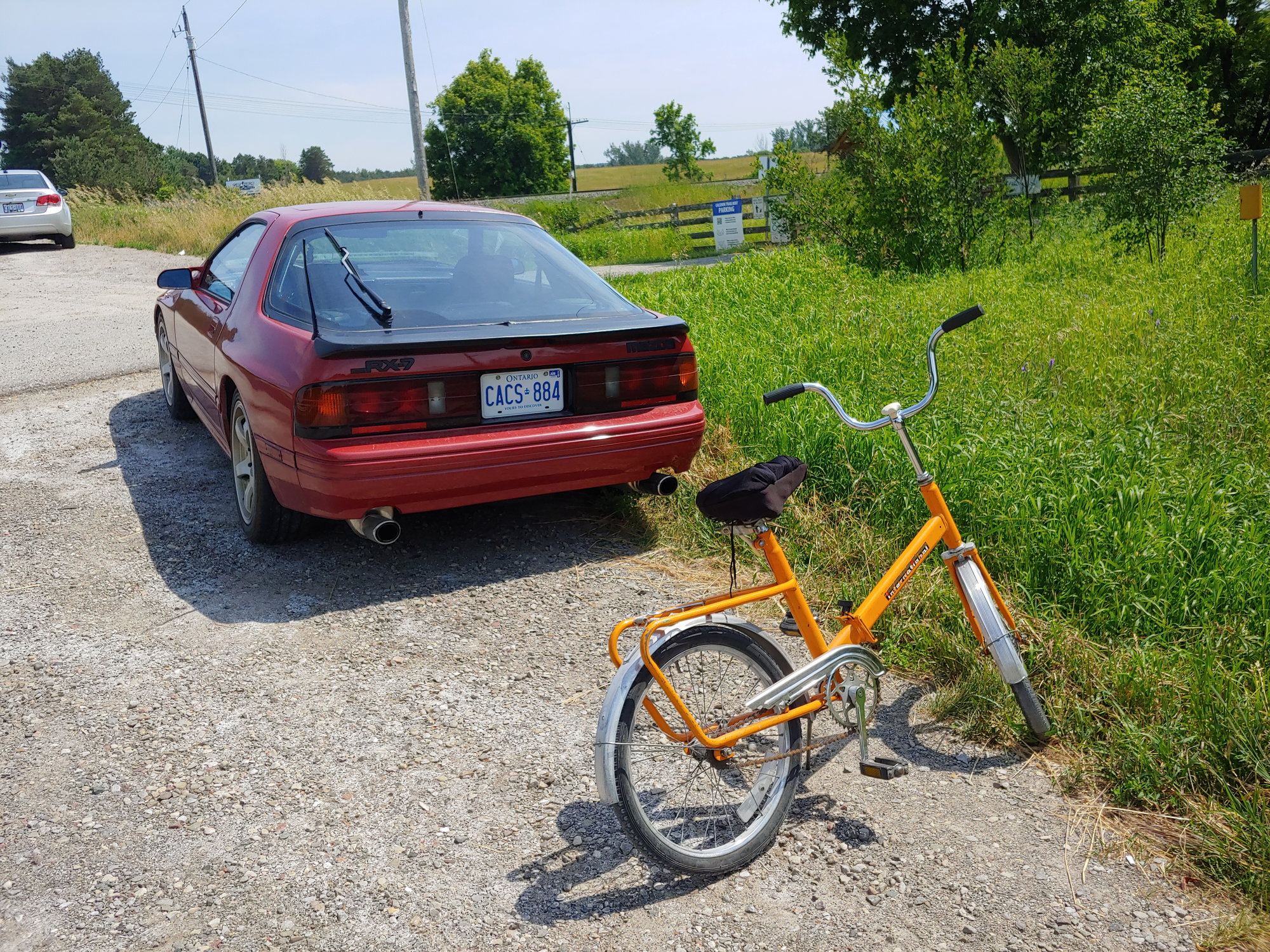
My legs are killing me since it's fixed gear, but the ride was nice. Nicer is that the car is reliable enough to just get in and go. That's the kind of reliability I'm going to try to maintain after the turbo swap, which is part of the reason my power goals are so mild. It doesn't matter how fast the car is if it's always on jack stands.
Speaking of which, another few parts came in today:
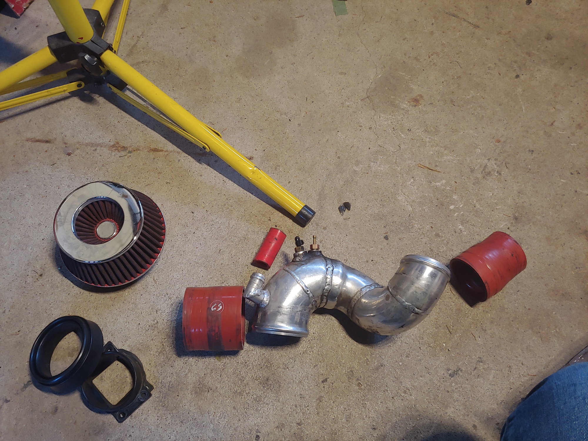
Awhile back Rx7Club member Carsebuco and his wife were looking to install the stock intake box back on their 10th Anniversary and remove this turbo inlet duct and aftermarket filter. Now I had some spares so I sent them an airbox and snorkel for the cost of shipping. Then after this Turbo II engine fell into my lap, I really needed a TID. I prefer the OEM unit but it's expensive, and also requires me to keep the MAF in the system. They kind enough to send me the aftermarket TID for the cost of shipping (thanks again!), which saves me a ton of time trying to chase down the stock parts.
They included the TID itself:
An adapter for the MAF (which has a square outlet):
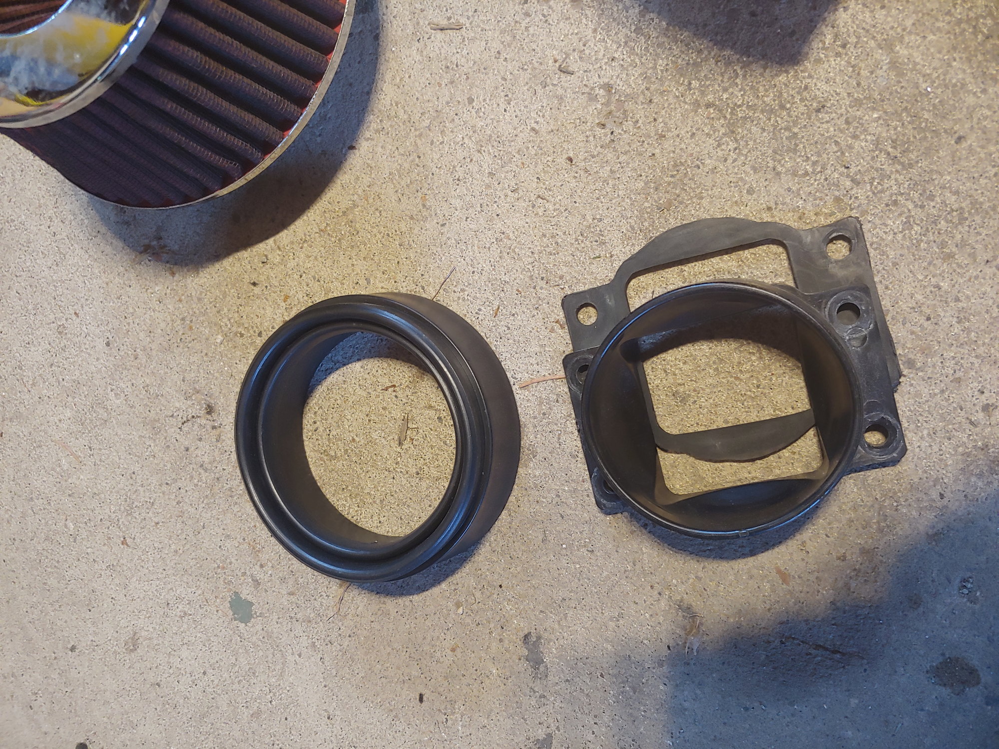
And a cone filter:
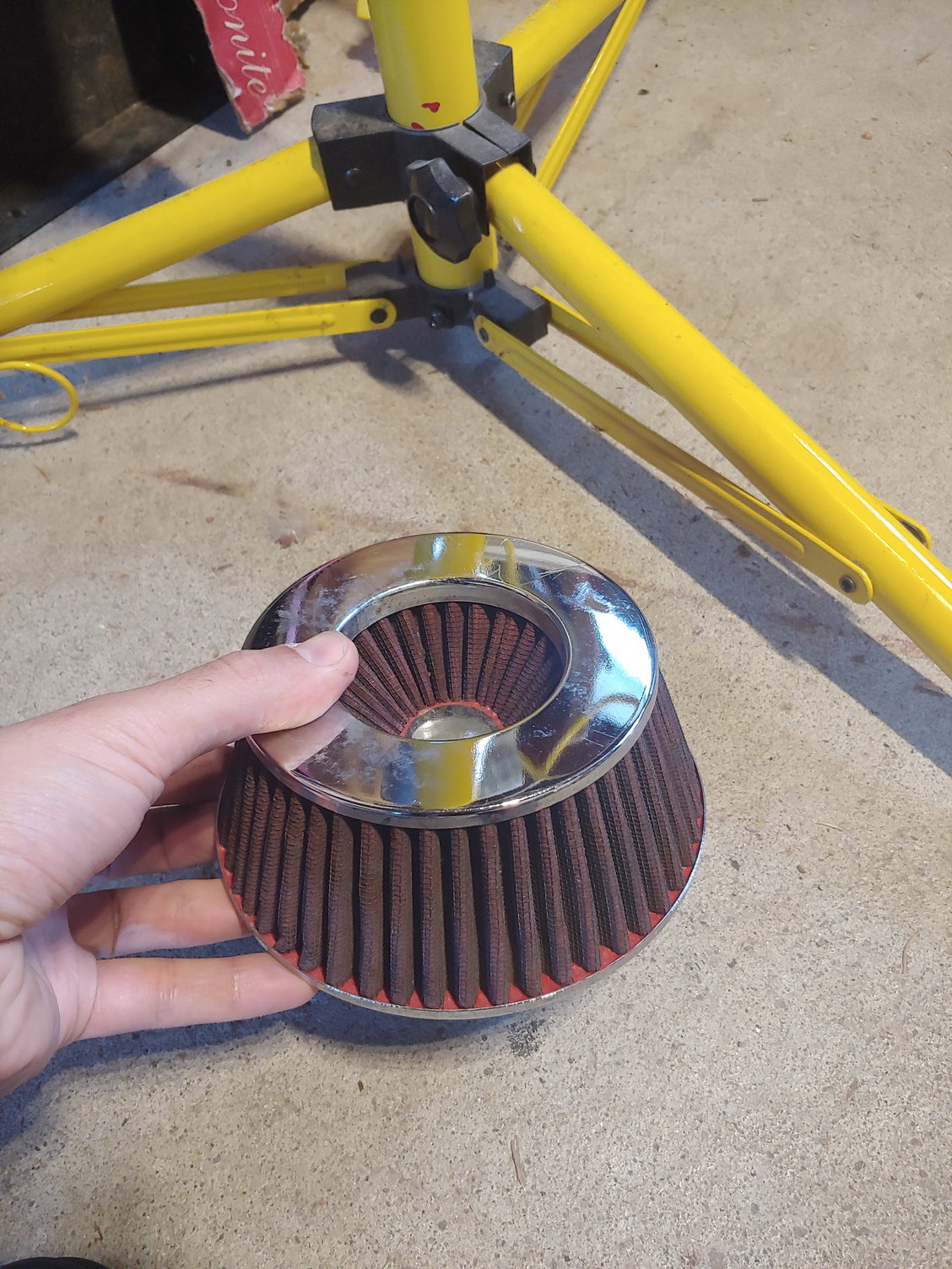
Now once I have the standalone sorted out I will be running speed-density. This lets me eliminate the MAF. However, we all know that a cone filter exposed in the engine bay is really a hot-air intake. For startup and testing I can install the TID with the cone filter, but long-term I really want to connect the TID to the stock intake somehow. I may be able to using that MAF adapter in reverse (connected to the airbox instead of the MAF), but if not I will design and 3d print an adapter to fill the same purpose. The stock airbox can already flow plenty of air, and it includes a snorkel to inhale cold air from the front of the rad.
Until next time :)
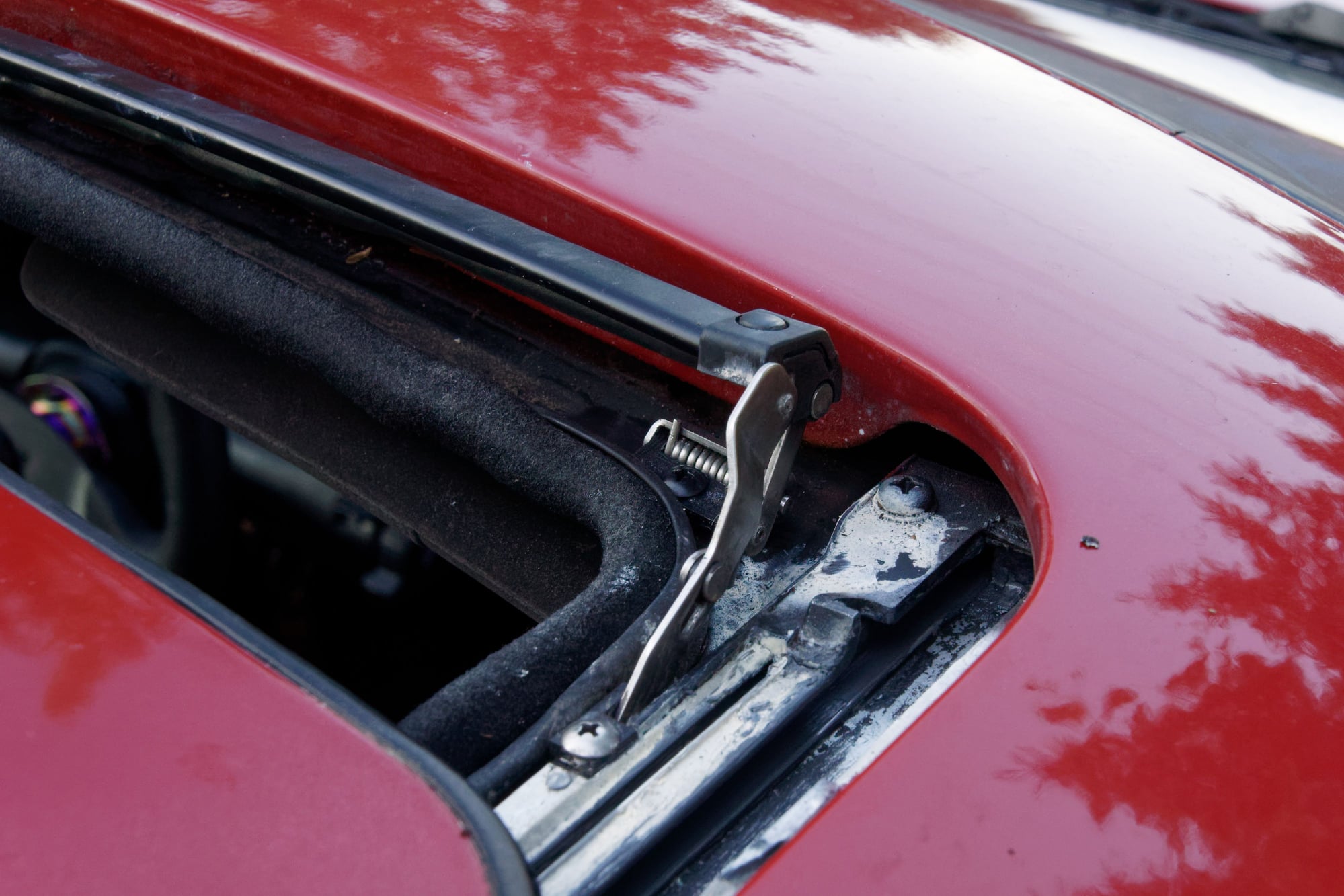
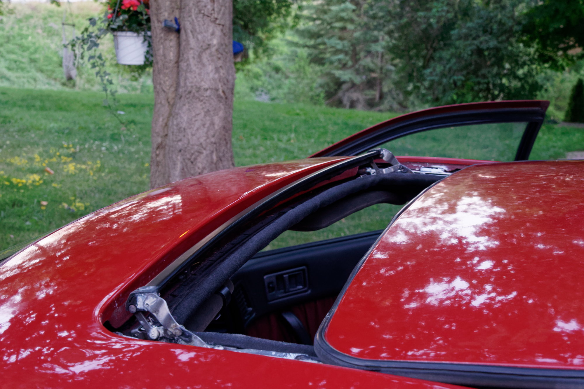
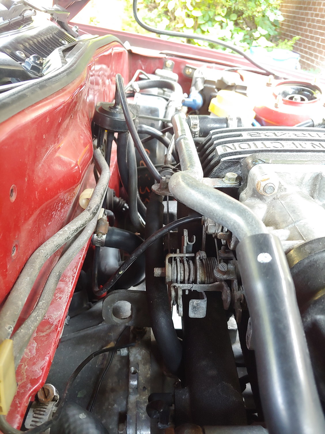
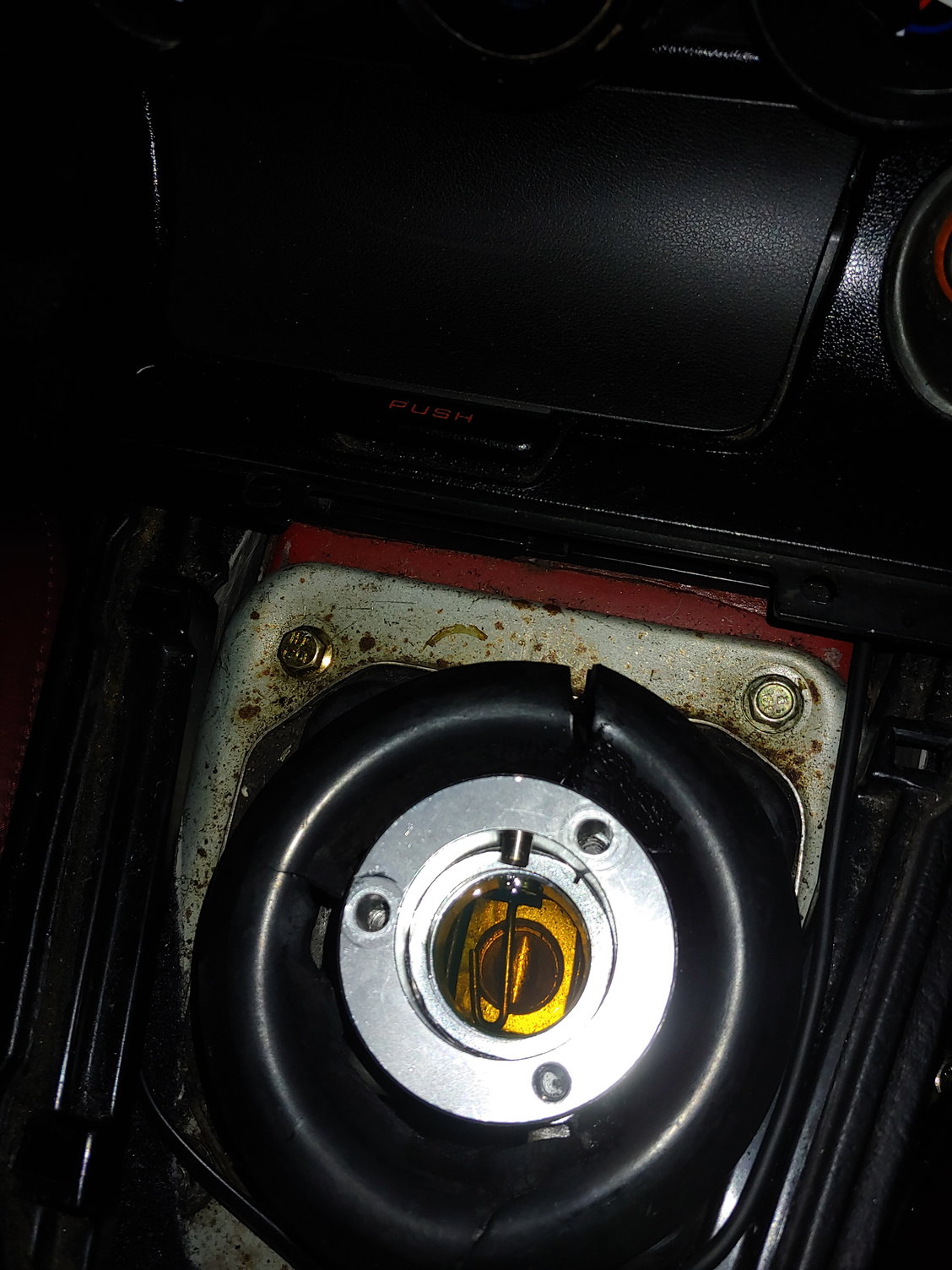
So the latest thing that's been bothering me has been the deflector for the sunroof. If you don't know what this is, yours is probably broken too. See the black bar at the front of the sunroof opening?
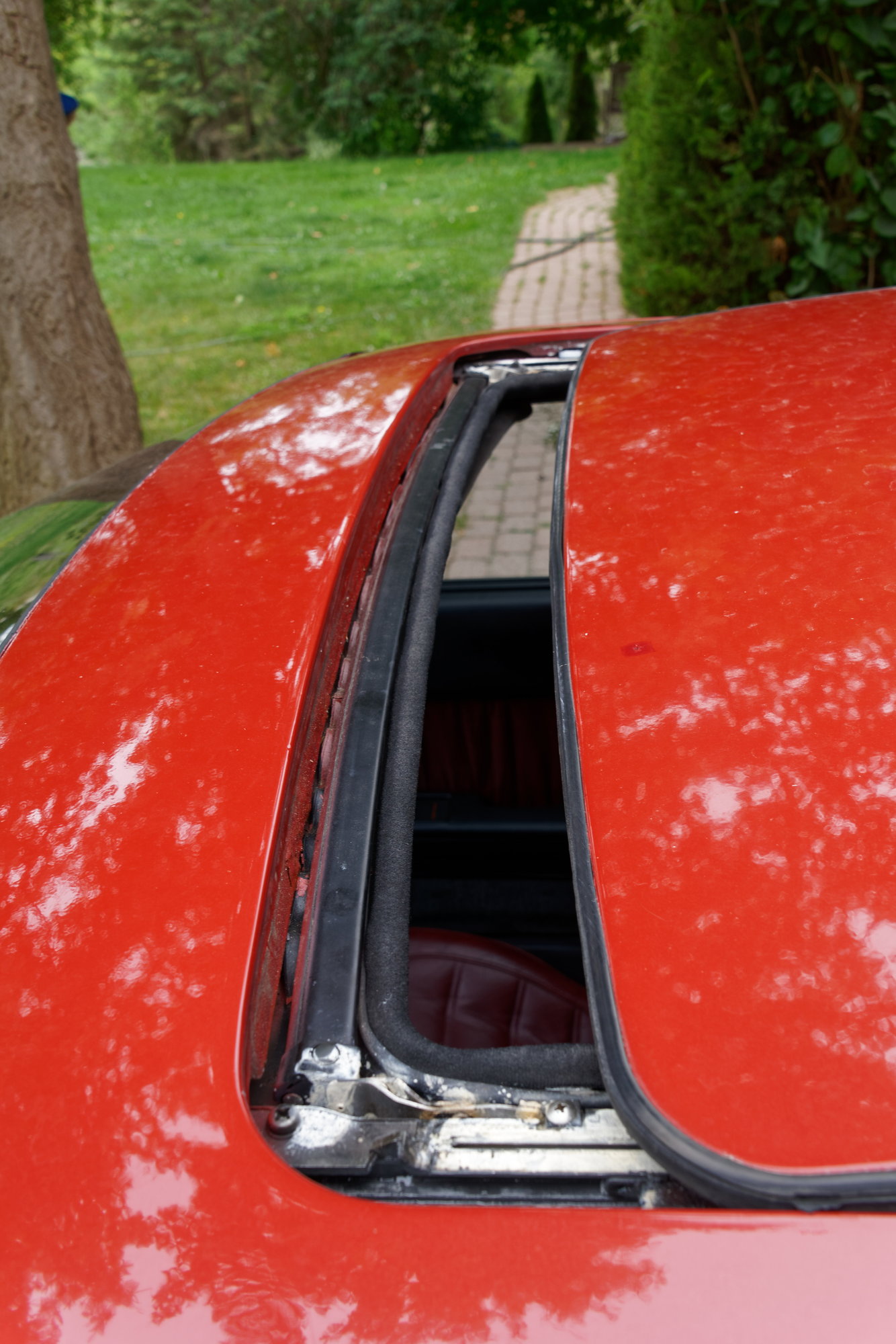
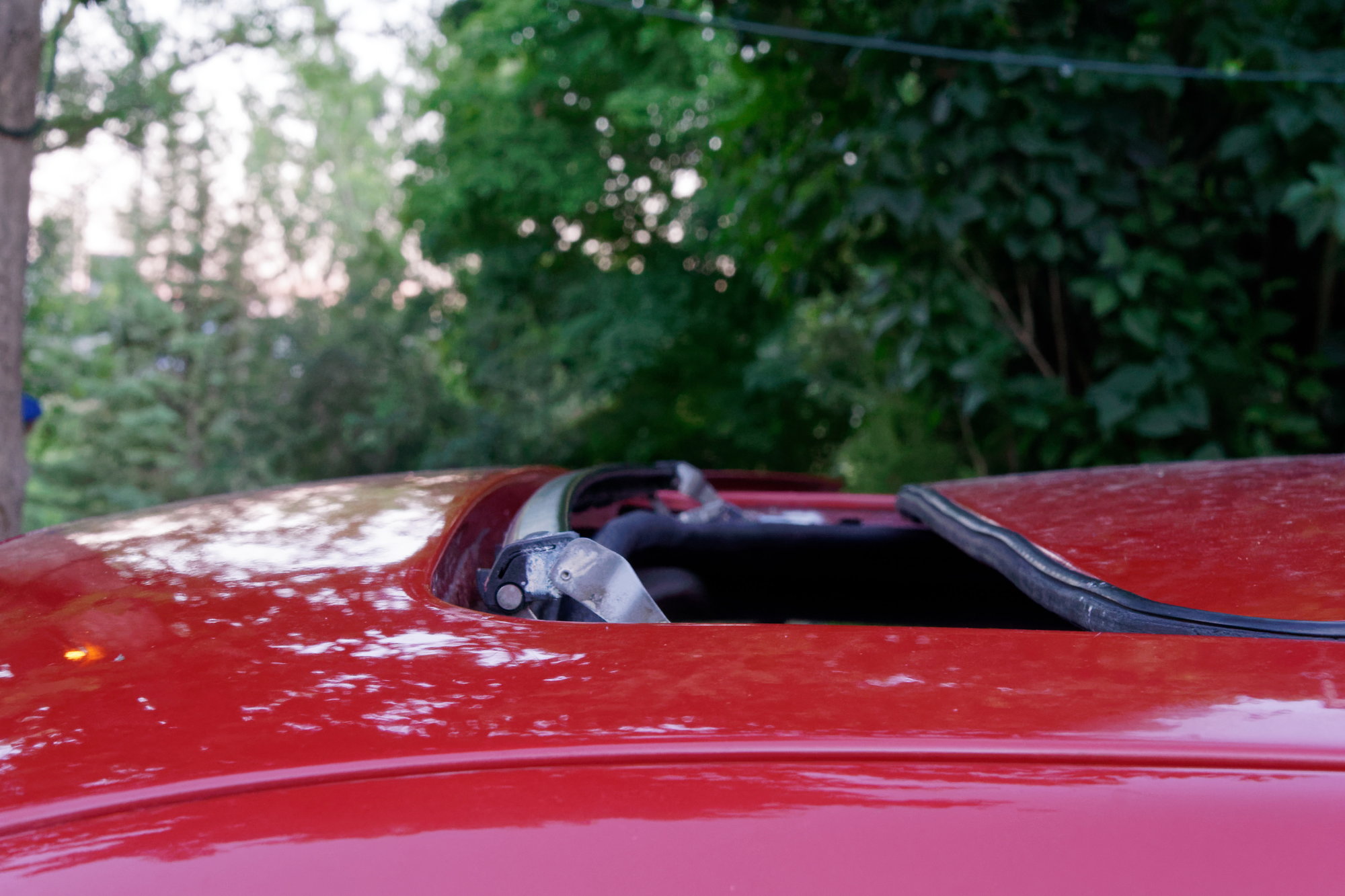
That's supposed to pop up on it's own to deflect wind noise. Mine is unfortunately suffering from ejectile dysfunction. To diagnose the problem, two JIS screws need to be removed per side. There are two silver ones here:
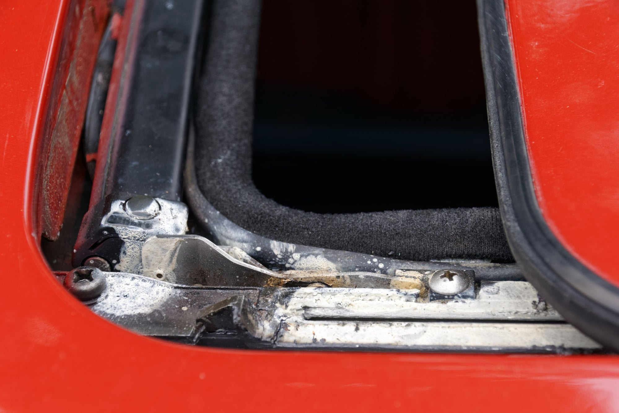
And two black ones under the bar. Remind me to clean up all this lithium grease...
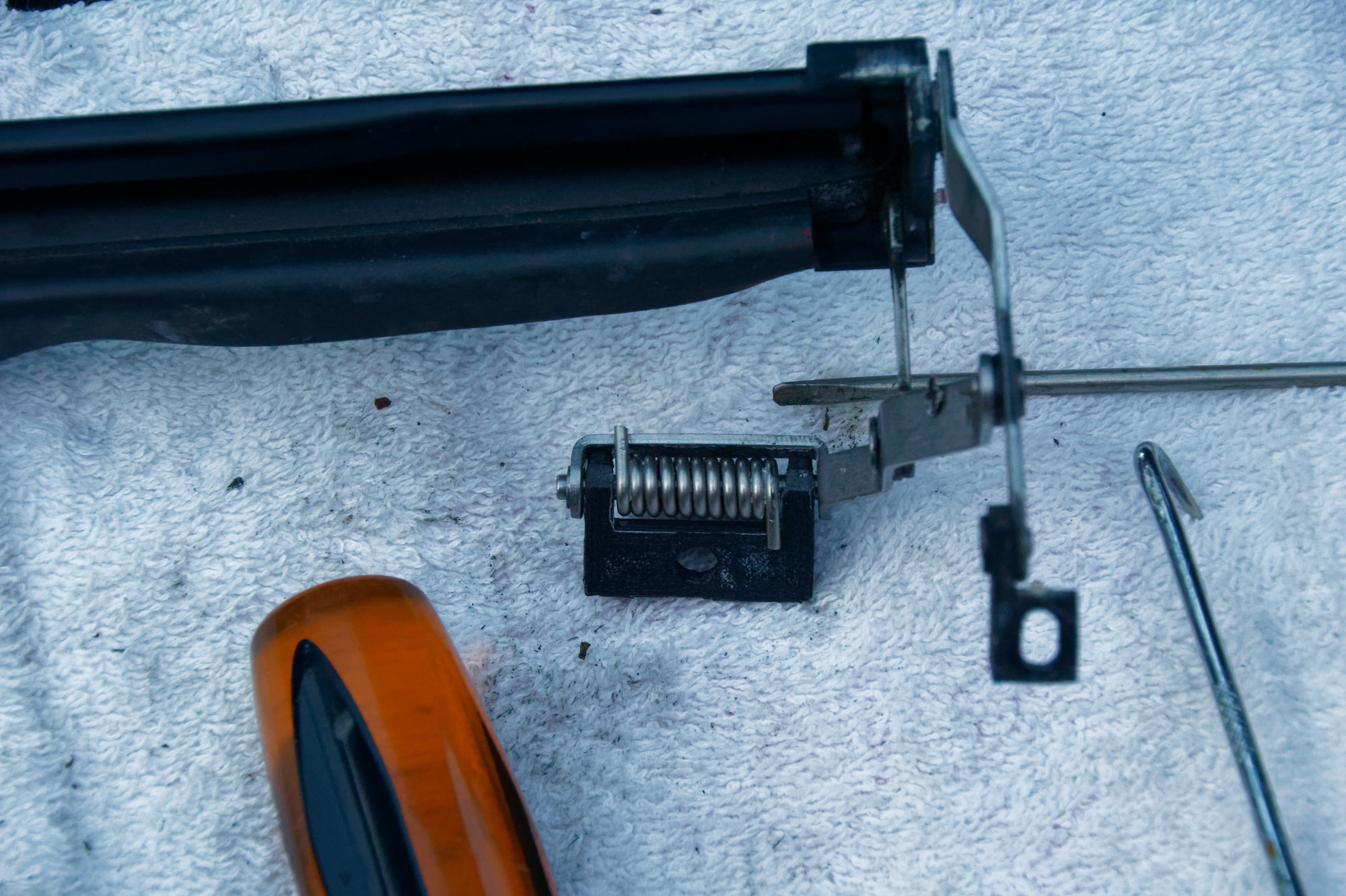
Once the deflector is out, the problem is pretty obvious:
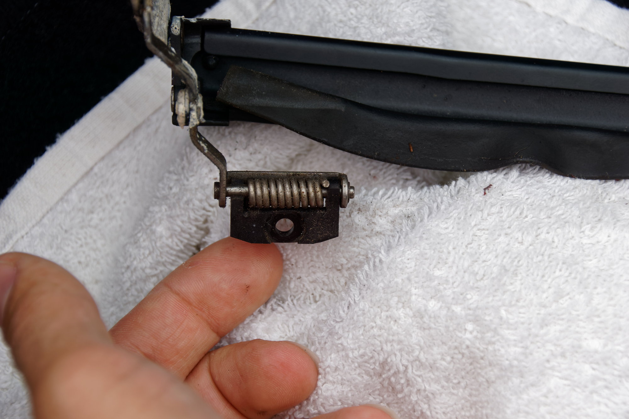
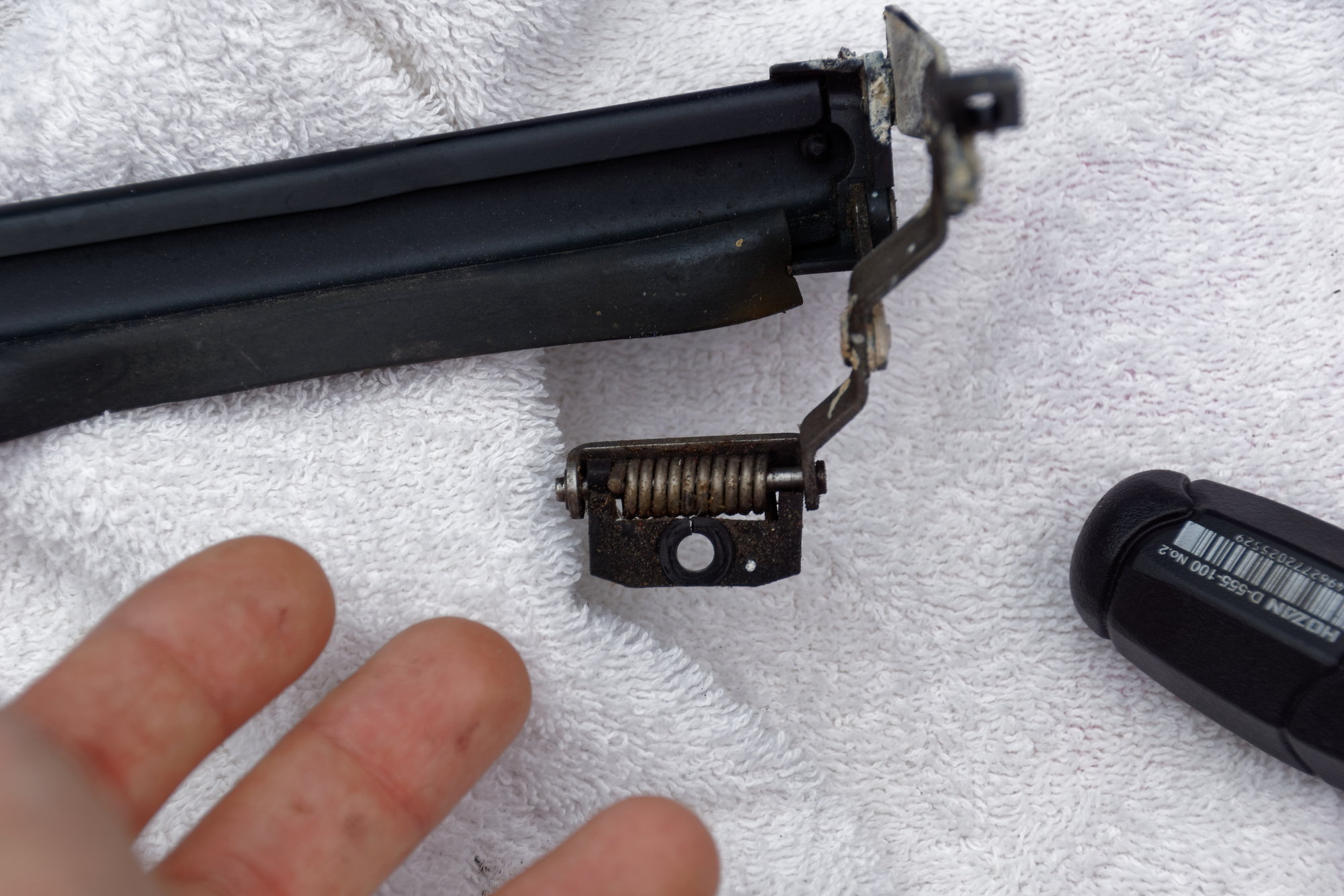
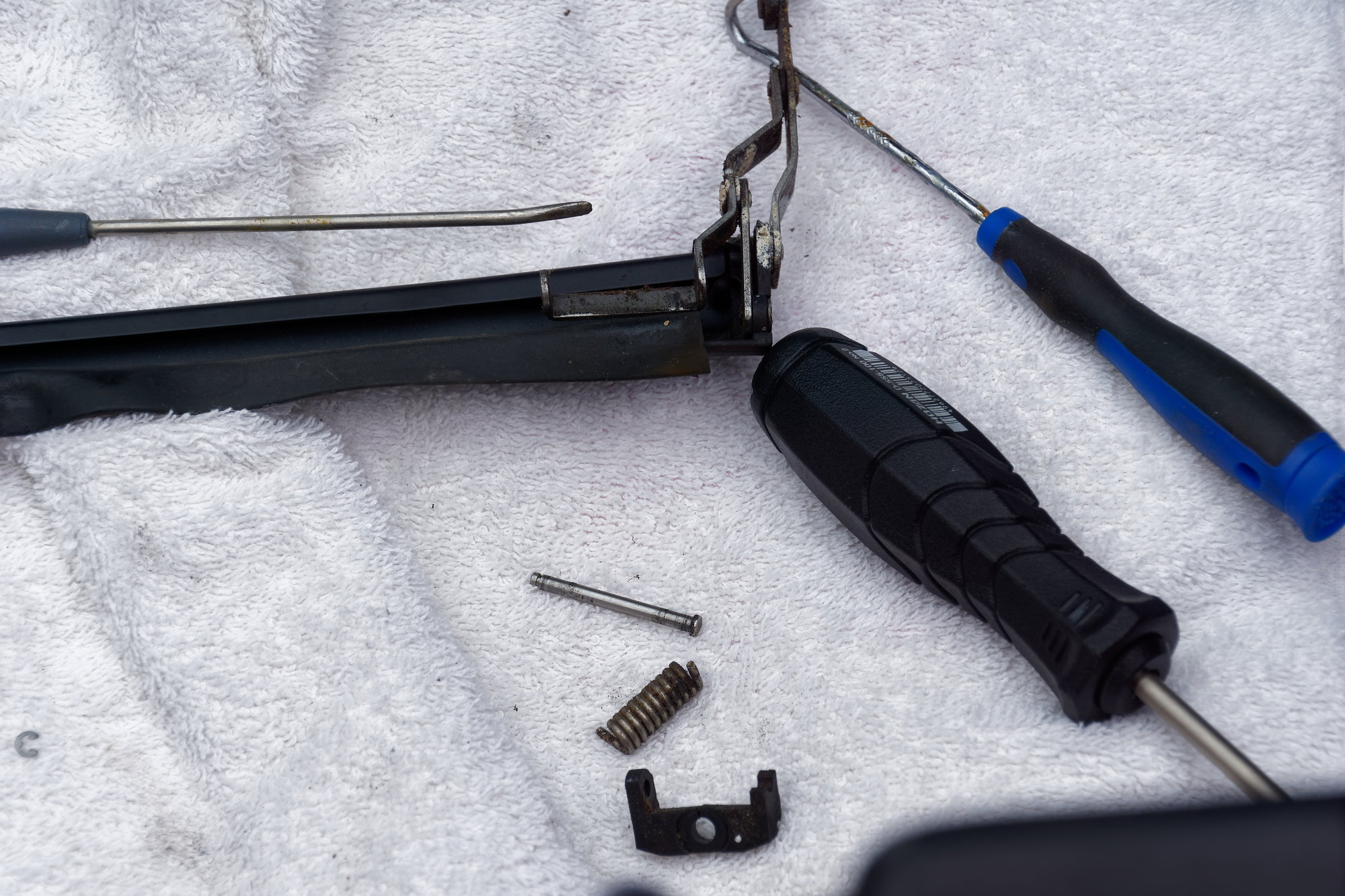
Both of the black plastic pieces are broken. Now, I did look to see what this part costs. Apparently it's only sold with the entire bracket. Left side is NLA, right side is available from Atkins for $80 USD. That means even if you could get them, it would be $160 USD before shipping. Highway robbery, when all you need is the black plastic piece. To take it out, there's one small retaining clip and then it comes apart:
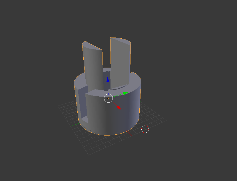
After some time in Blender:
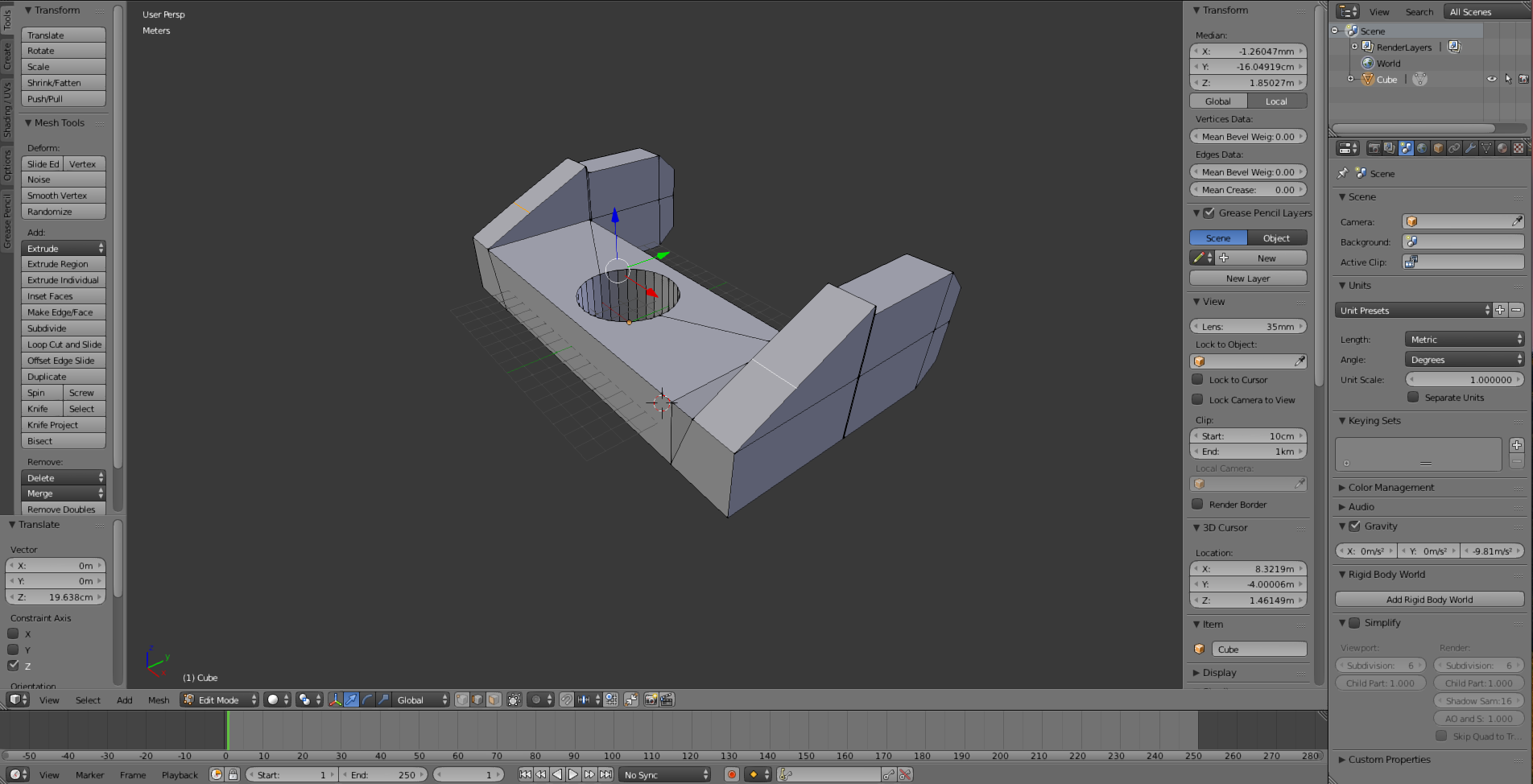
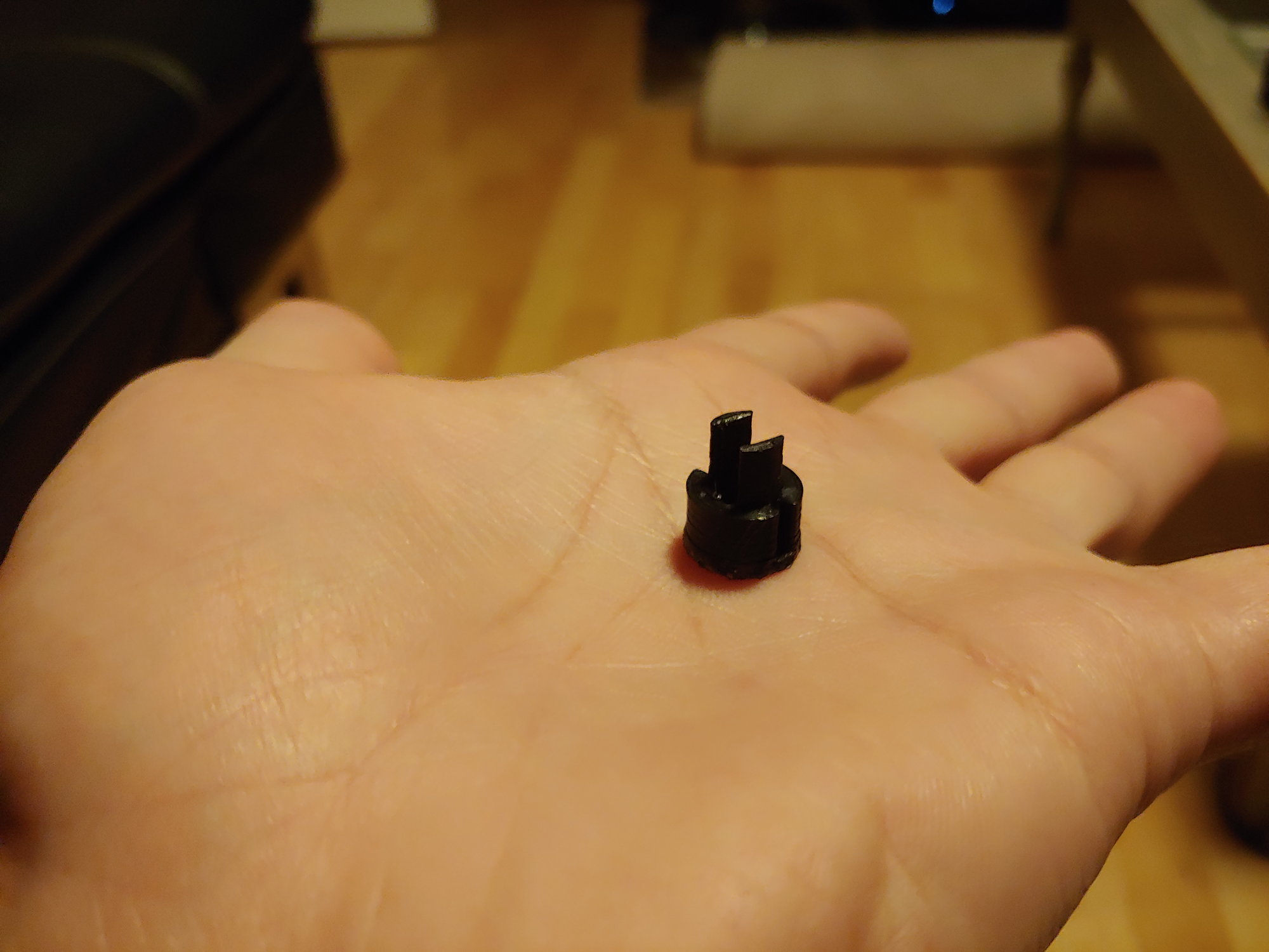
The part looks simple, but there are about 6 revisions in this part. The bevelled corners are necessary to prevent it interfering with the mount on the body of the car, the small step in the "arm" part is necessary to seat in the flat part of the linkage, etc. Overall (including test fitting and printing) it only took about 3 hours. The only post-processing required for the part is drilling the holes for the pin. See the following blurry picture:
That's actually a prototype, which is why the corner is bevelled with sandpaper instead of in the model.
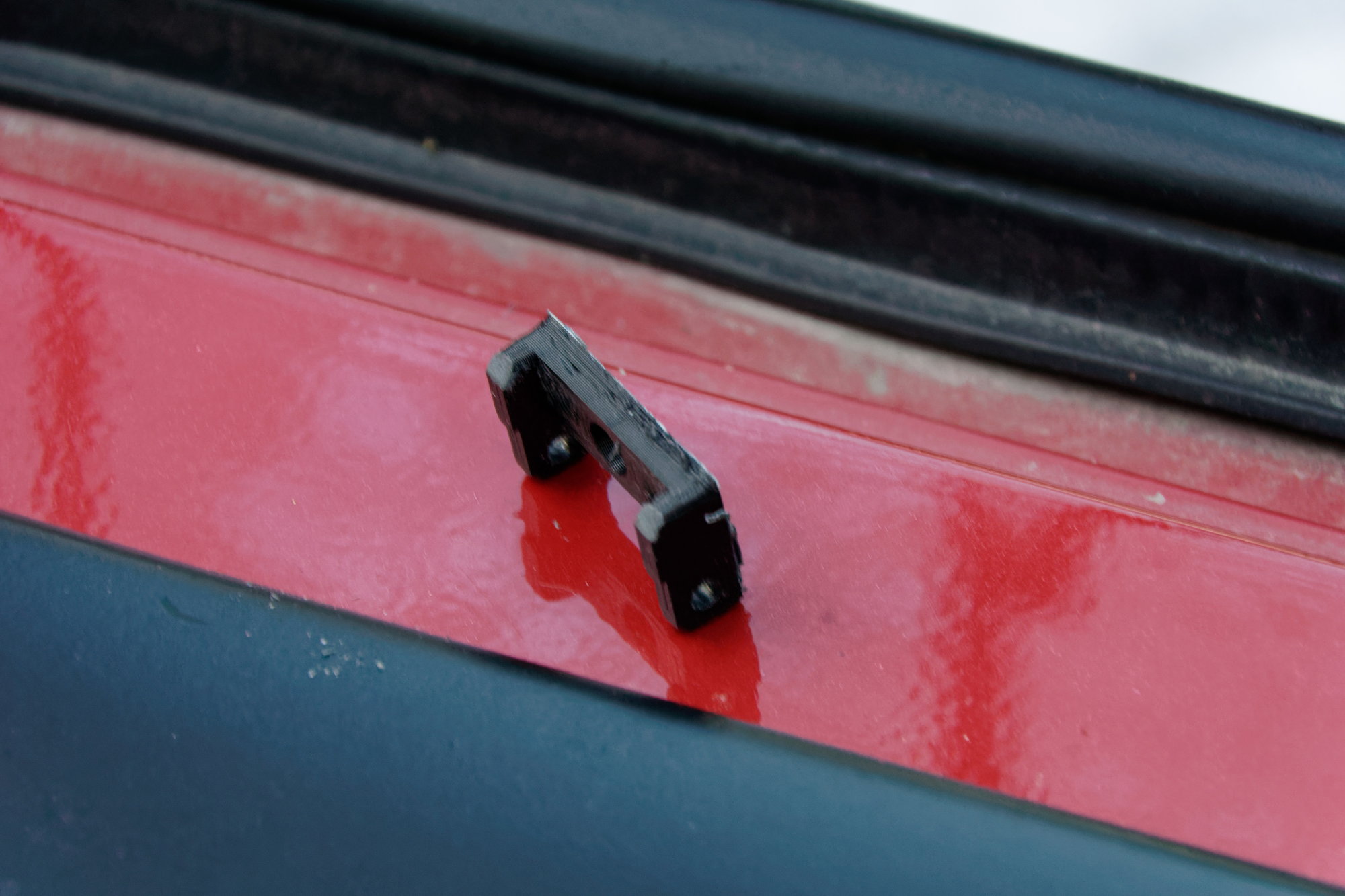
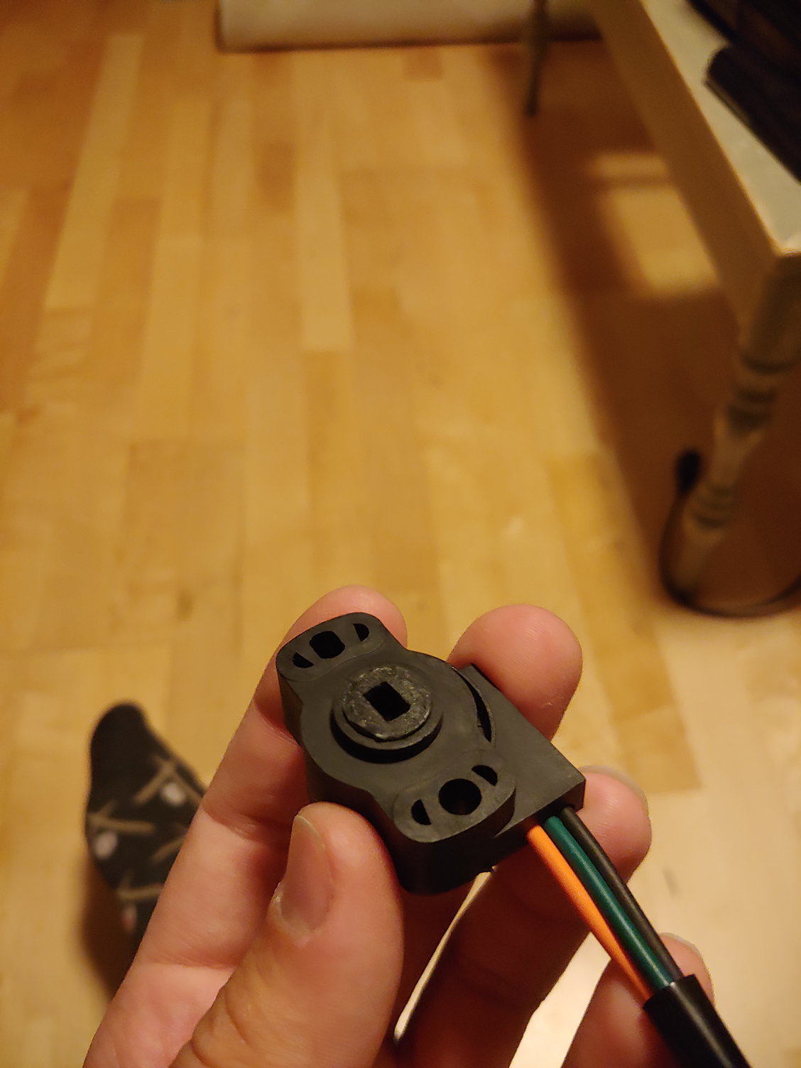
Installed. I'm not sure if this is actually the correct orientation for the spring. I can however say that this does work perfectly:
Installing the deflector can be tough since it's spring-loaded and wants to pop itself free. Once the new plastic piece is screwed in on either side, the best thing to do is to gently manipulate the linkage where it needs to be until the rear screws are partially threaded. Then gently tighten them while making sure nothing is binding. The black deflector piece will also want to be tilted away from the front of the car, so you need to gently roll it the other way until the rear screw holes line up.
All done:
Does it make a difference? I'm not sure, I actually have yet to drive it. Will report back once I find out. For a cumulative 3 hours work and probably 10g of ABS filament, it's worth it just to know the part is fixed. If anyone needs the STL file, shoot me a PM.
Until next time :)
I've had power locks controlled by my alarm system for a few years. Installing them was fairly simple: The alarm itself has outputs that it pulses + / - depending on whether it's a lock / unlock command, and that switches a set of 5 pin relays arranged as an H-bridge which is hidden inside the hollowed-out factory speaker under the dash. These relays then control the lock actuators I installed in the doors, giving me remote lock and unlock.
I never actually made use of the hatch-popping function though, since I couldn't find a good place to mount the actuator at the time and then I put it on the back-burner. I decided today was the day, so armed with some wiring, a relay, and some bicycle cables I set out to make the remote controlled hatch a reality.
Wiring was easy; the AUX output from the alarm runs to the back, then meets this relay I tucked behind this support:
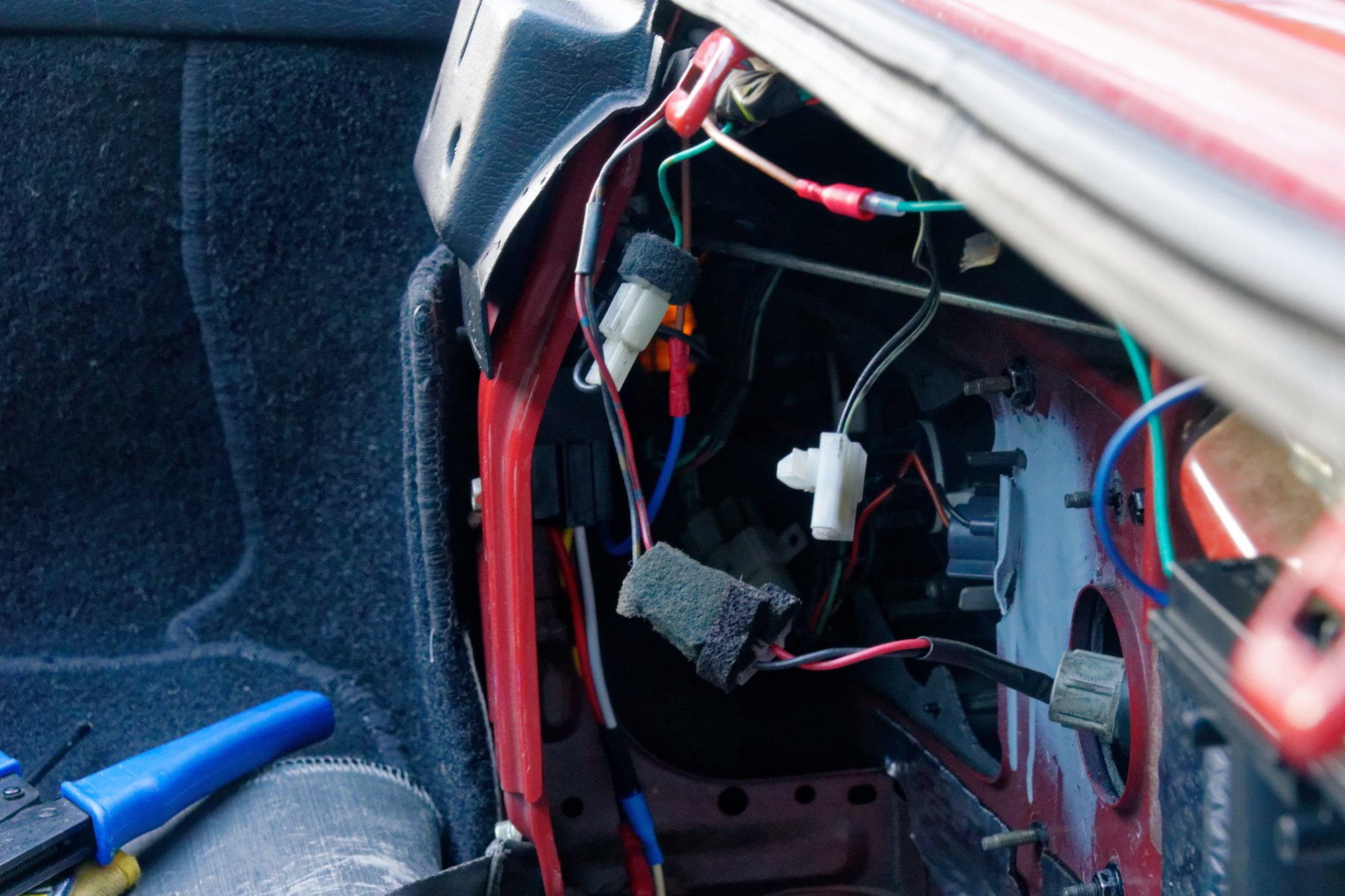
The alarm switches ground, so I needed a +12V source as well as a ground for the actuator. I found them both in the same area:
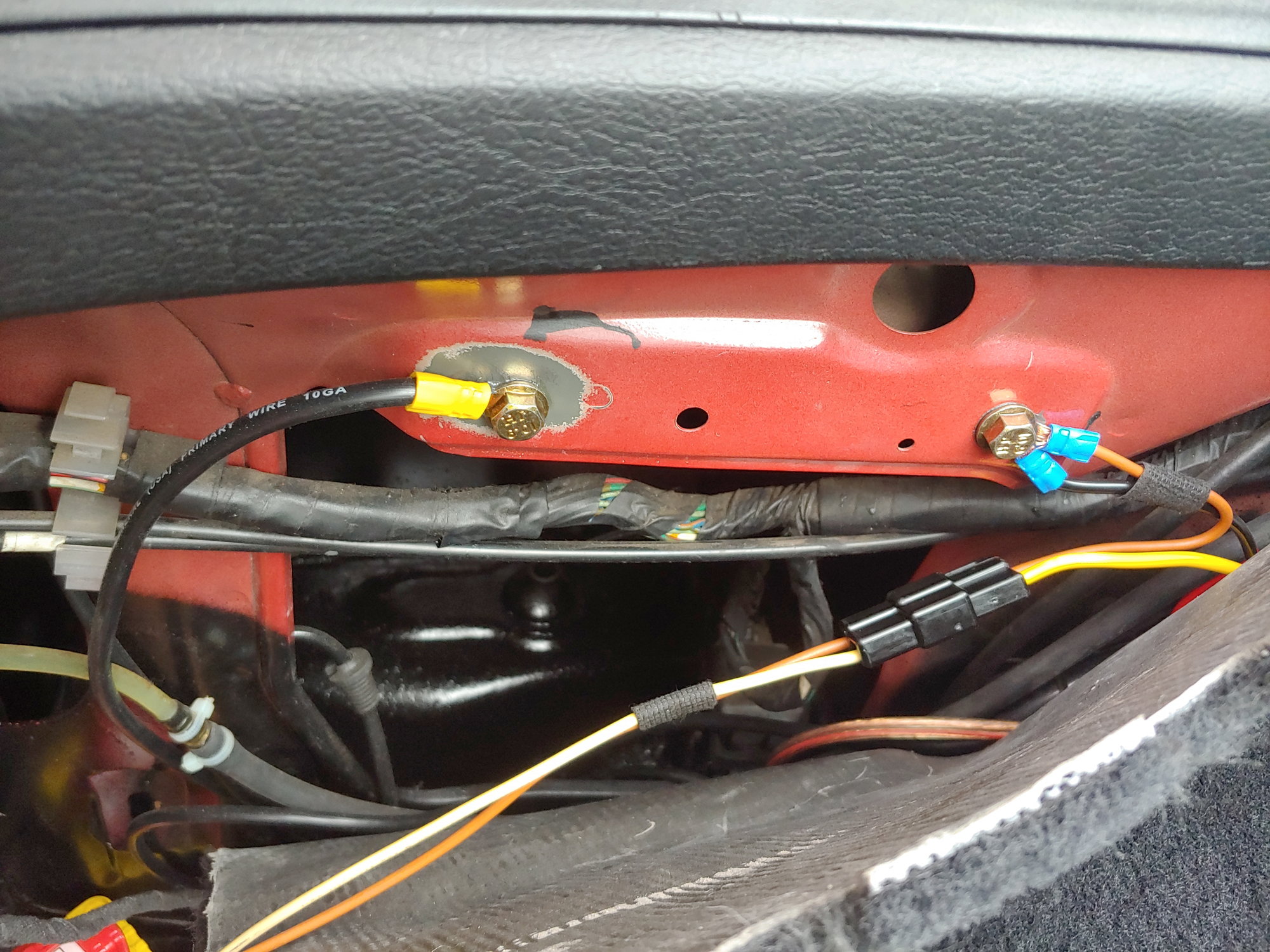
The +12V comes from the NC terminal of my fuel-pump relay. This is really nifty, since it also prevents using the trunk popper by accident if the car is running. The ground is a ground of course, and the connector is a factory-correct Yazaki that I had around.
Then armed with my bicycle cables, I went to find an inventive and out-of-the-way place to tuck the actuator and make some brackets for the cable. So I'll admit I was a bit disappointed to find a perfect factory location, with existing holes for the self-tappers:
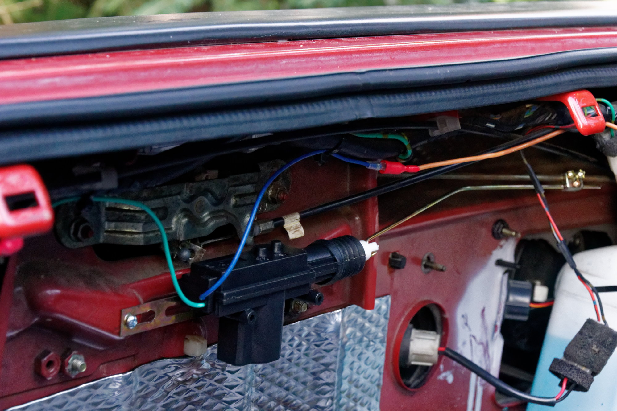
Yup. No fancy cable-actuation needed. Not sure why I didn't see that years ago. Anyways, I bent the rod to match and it seemed to work fine for the dry run. Now time to test it:
https://www.youtube.com/watch?v=fD3LyfCdeNg
Beautiful, if I may say so myself. And not counting the alarm which I already had, it cost like $15 total for the actuator and relay.
That's it for today. If all goes according to plan I should be picking up some other neat parts in the next few days. Until next time :)
I've basically known for awhile that my engine management solution for the Turbo swap would be a Megasquirt. As far as cost-effective solutions for ECUs, there are basically three options:
- An Apexi Power FC, using an adapter harness.
- An older used Haltech unit
- Megasquirt.
An Apexi PFC works, and it works well, but the reason people choose it is usually that it's a drop-in swap. But it's only officially available for FDs. For FCs, you either need a non-standard AP-Engineering modified unit or an adapter. Then consider that you have to add in the cost of the adapter, the FC-Datalogit to tune it, FD coils, and the cost advantage vanishes. Let alone that it is relatively limited compared to modern options as far as I/O and engine protection.
The Haltechs that can be readily found used for a similar price to a Megasquirt are quite old. As in, old enough they need to be tuned with a DOS emulator. While it would be cool to tune my car with my Toshiba T3100e, the novelty of lugging a 286 computer out to the car every time would wear out quickly. Even with an emulator, it's just a bit too clunky for my taste.
So Megasquirt it is then. I was all prepared to buy a kit and build myself an MS3 (as building it yourself is still the cheapest way to do it), but then this popped up nearby on Kijiji. The seller and I found a fair price, and I picked it up this morning:
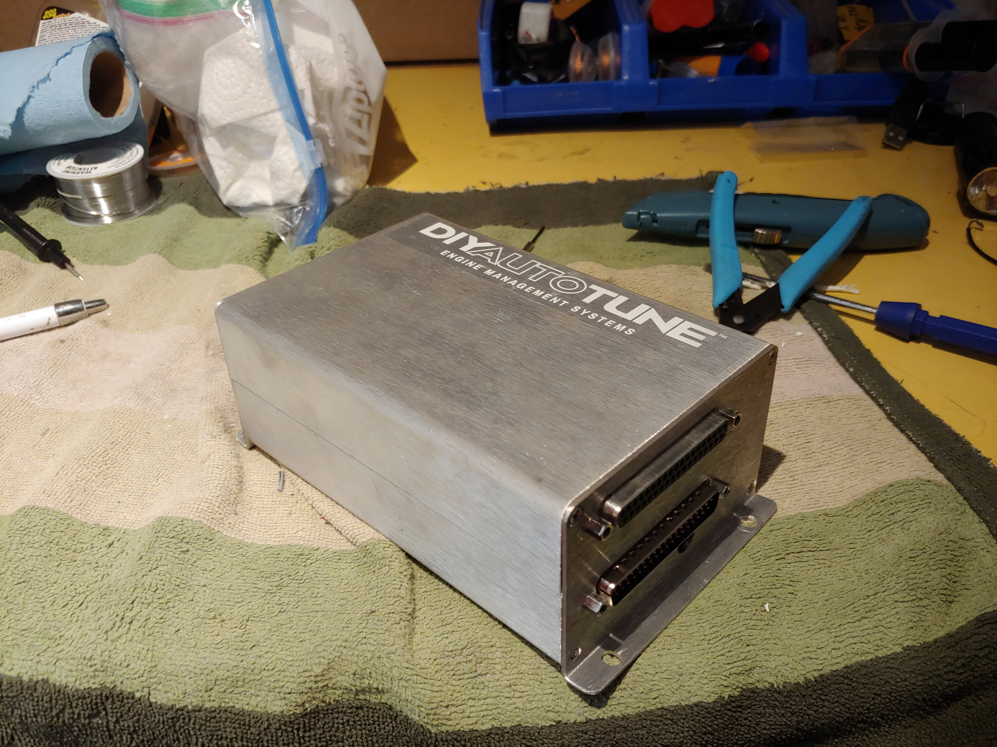
It's an MS3X on the 3.57 board. For the uninitiated this means that its a MS3 with eXpander, which is why it has two connectors. 3.57 is just the board revision, but the 3.57 boards all come factory-assembled instead of as a kit. The bottom connector includes the basic functions (power, CLT, MAT, TPS, etc) whereas the top connector adds extra I/O, injector and spark channels, and (importantly) a second trigger input which is needed for the stock CAS. And all for a lot less than it would have cost me to build one.
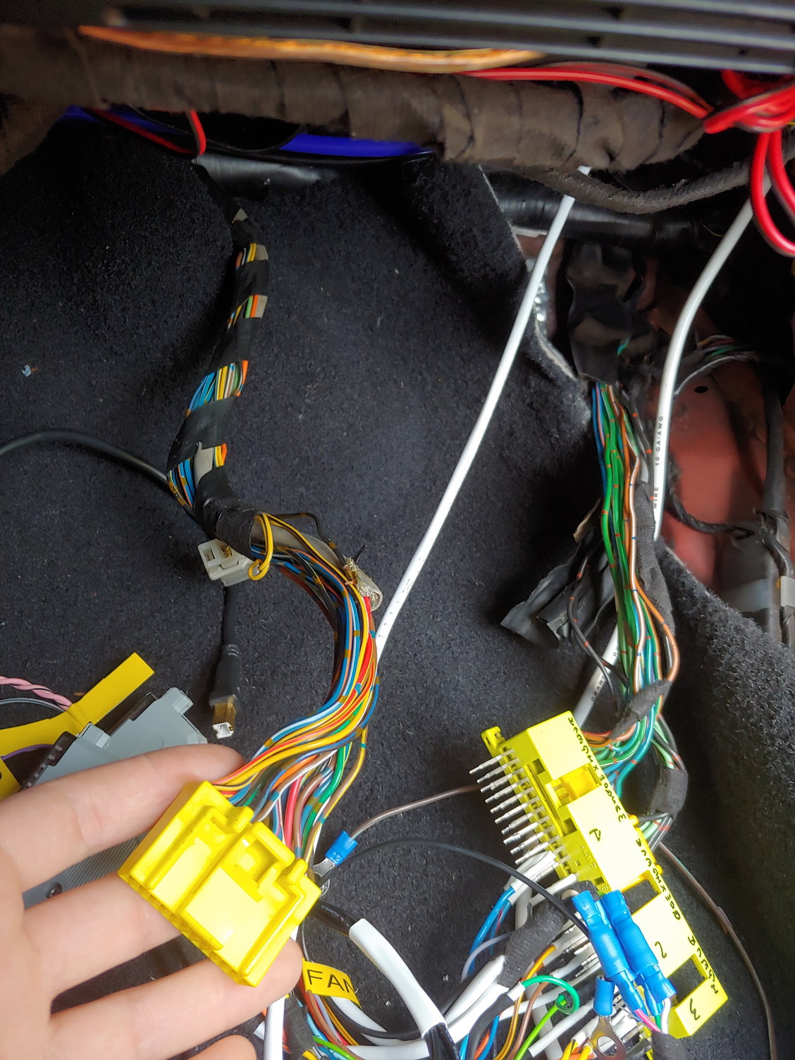
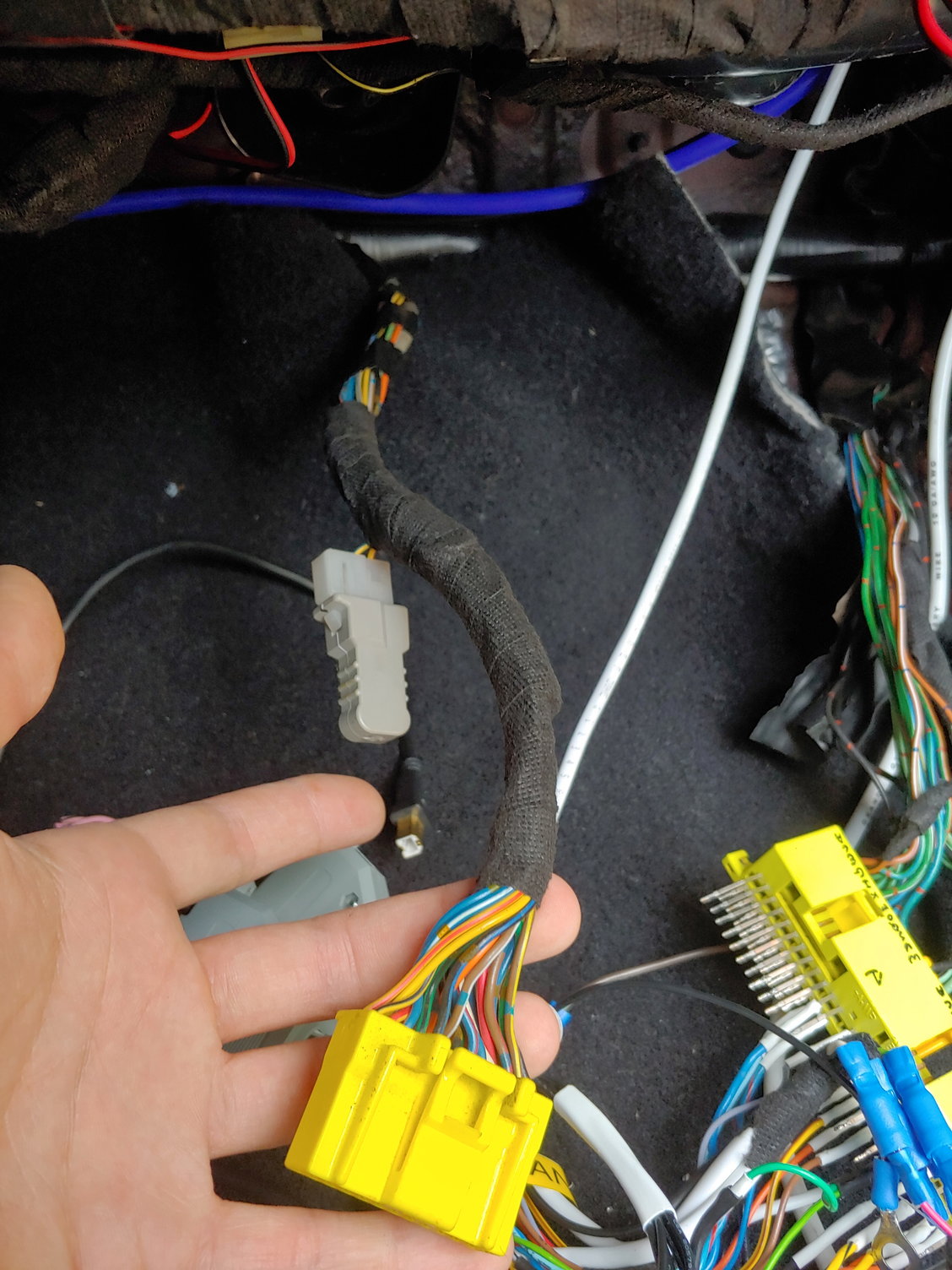
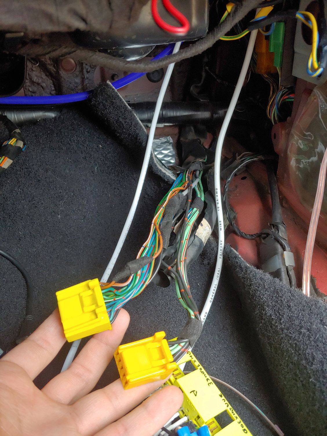
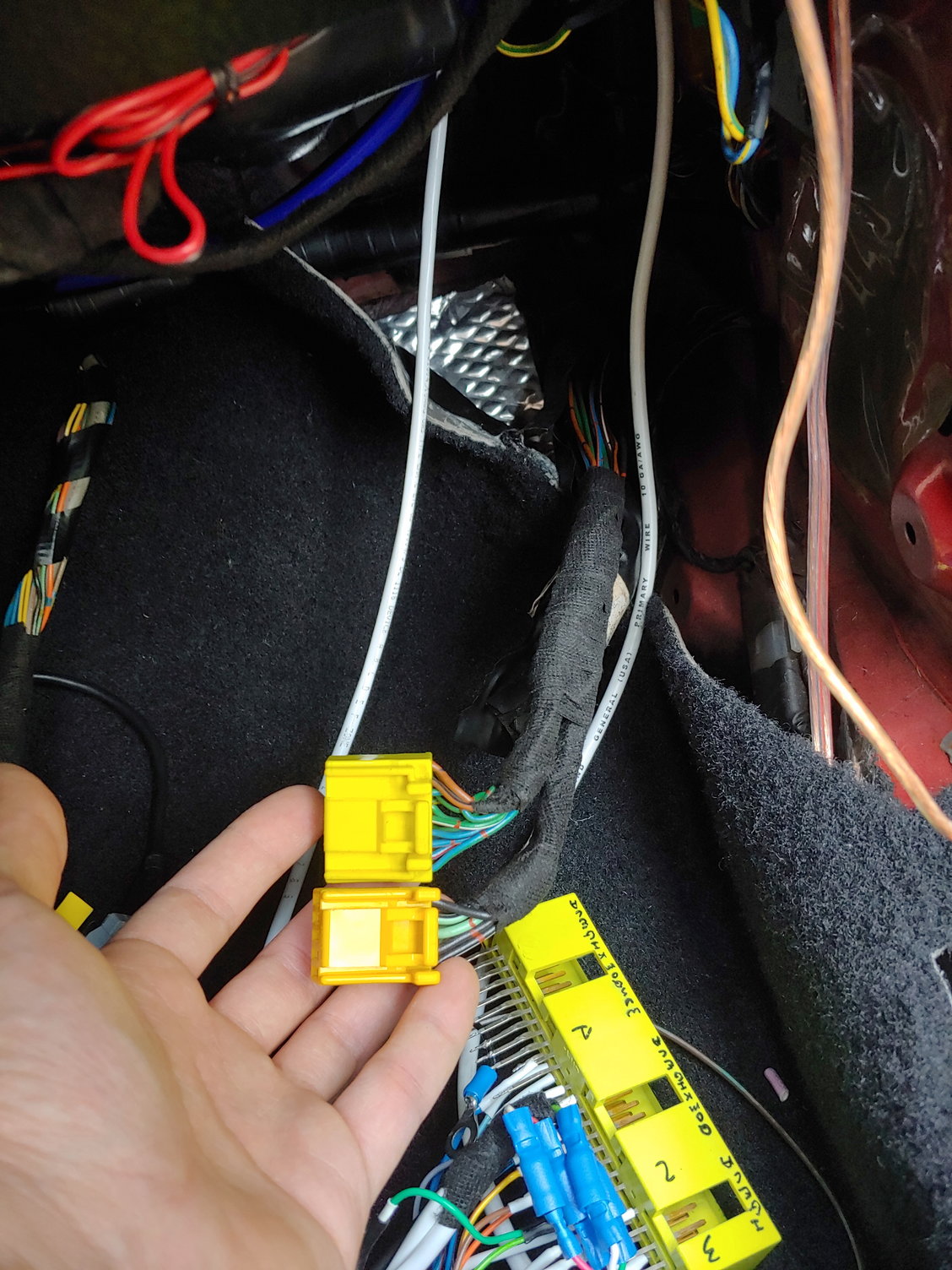
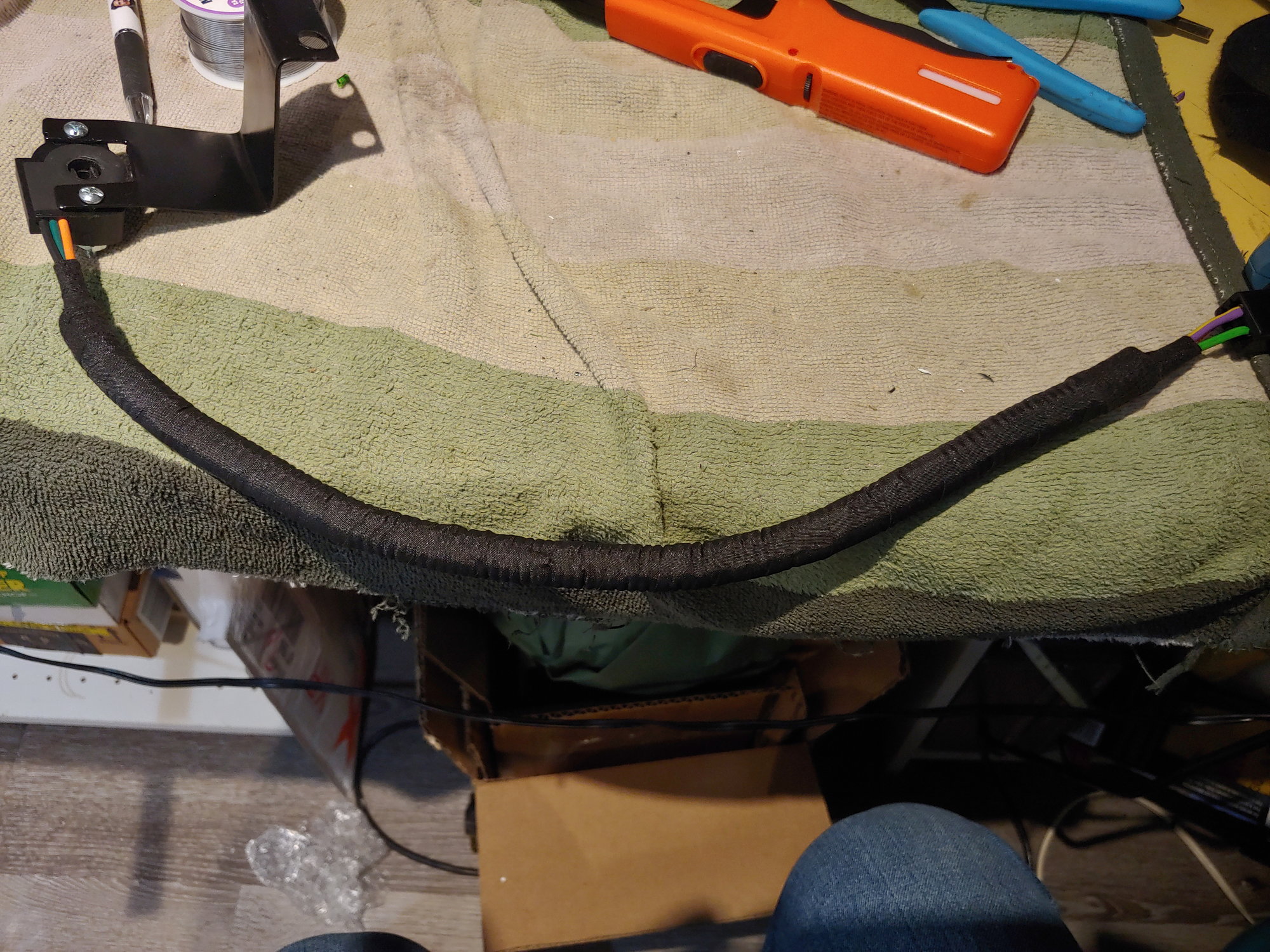
I've also created something nifty, although it will not be used once the turbo swap is done:
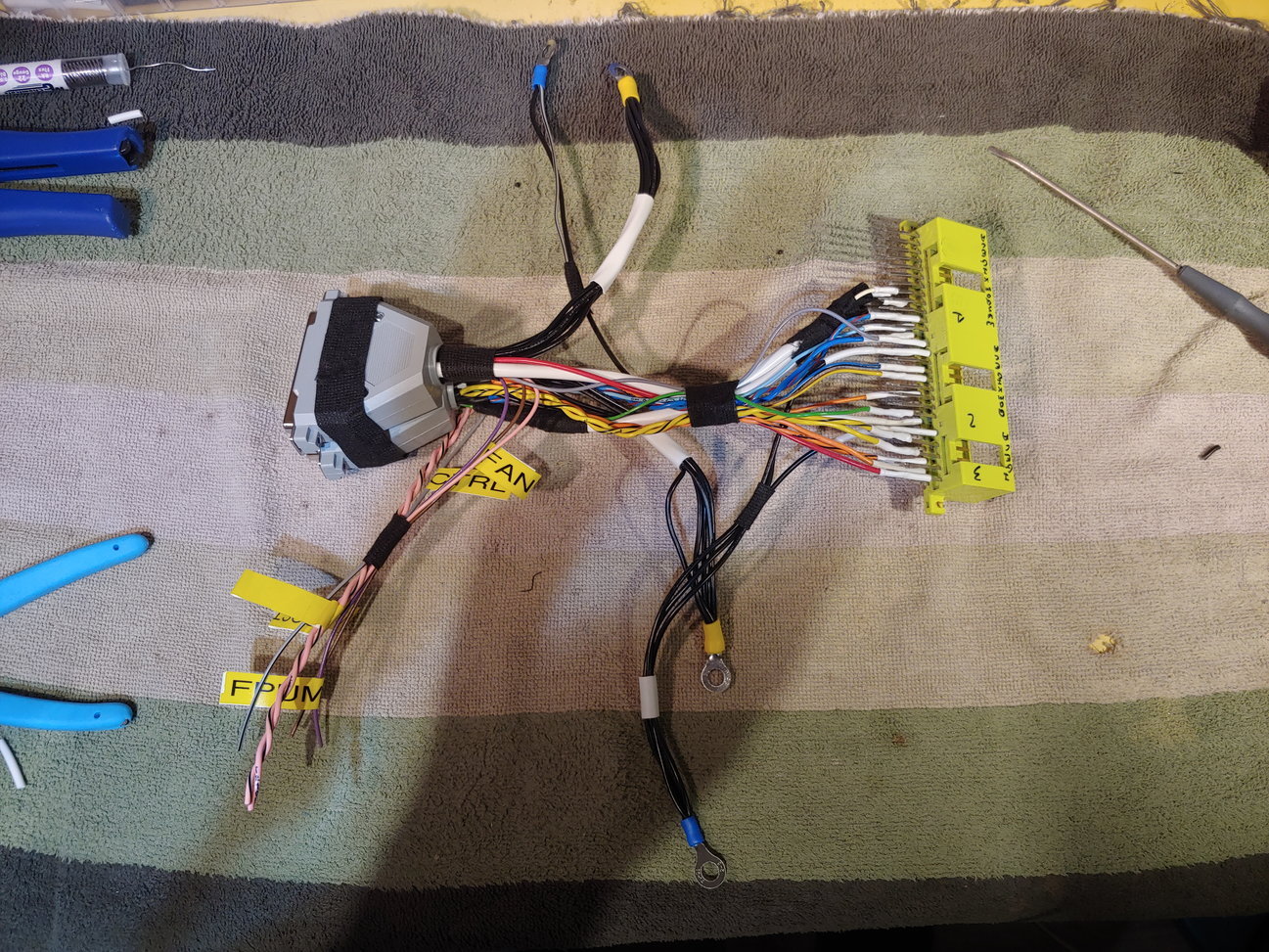
Ignore the grounds, this photo does not reflect some of the things I've learned about grounding. They will be altered before I actually install. I gutted a bad ECU for its connector, raided a pile of beautiful wiring my dad pulled from a Maserati Quattroporte parts-car, and made an adapter that makes it almost 100% plug-and-play with the stock S4 FC harness. Add a fresh dedicated ground for the ECU on top of the engine, disconnect the original harness ground from the engine (it is now redundant), vacuum line for MAP, and add the wideband connection. Hypothetically that should be all I need to do. We'll see how well theory translates to reality.
This is not going to be used for the Turbo engine as I will be making my own custom harness with fresh connectors and converting to the more common GM temp sensors. This adapter is to let me learn the ropes on my NA engine while keeping the installation reversible. I will be happy to provide the pinouts once I have tested to make sure I didn't make any errors, if anyone wants to replicate this setup.
I won't have time to actually install it for a few days, so that's it for now. Until next time :)
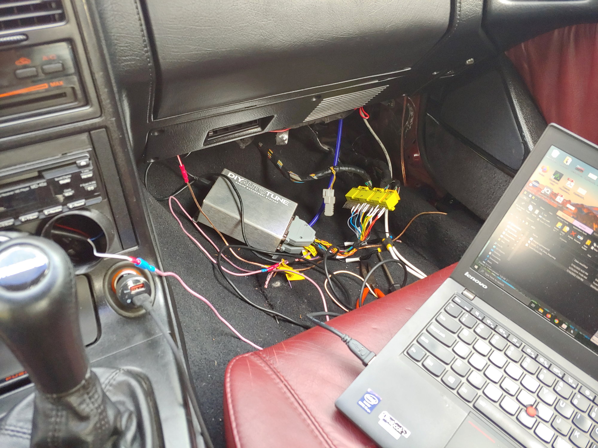
I left off saying that I wouldn't have time to install the MS3X for a few days. Unfortunately COVID protocols had other ideas. I'm fairly sure I just have a bad cold, but even with negative tests I need to isolate for 5 days from the start of symptoms. And I feel like garbage, but I was able to make some progress on the MS3X installation. Like I said, my little adapter harness made it almost plug-and-play.
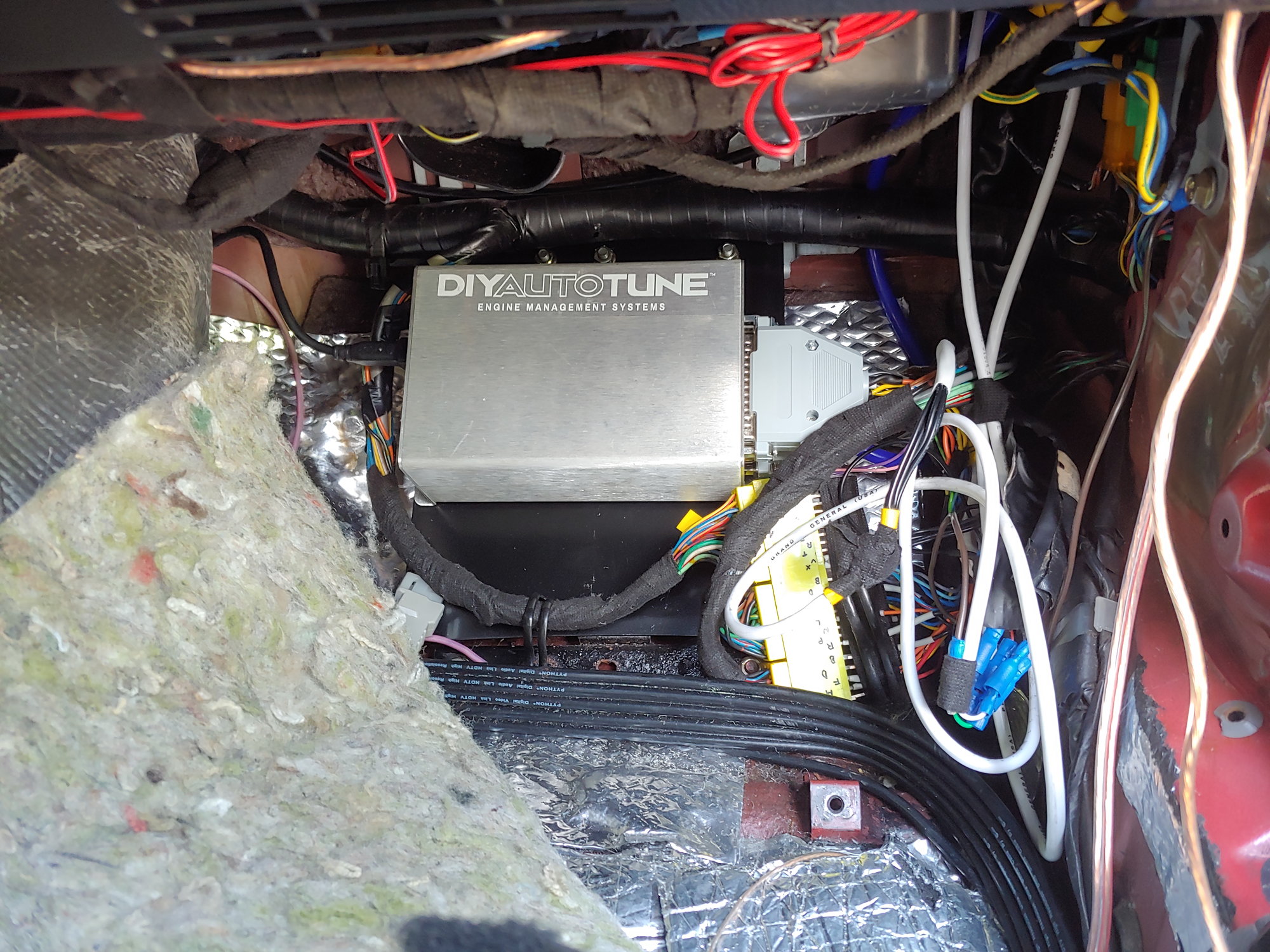
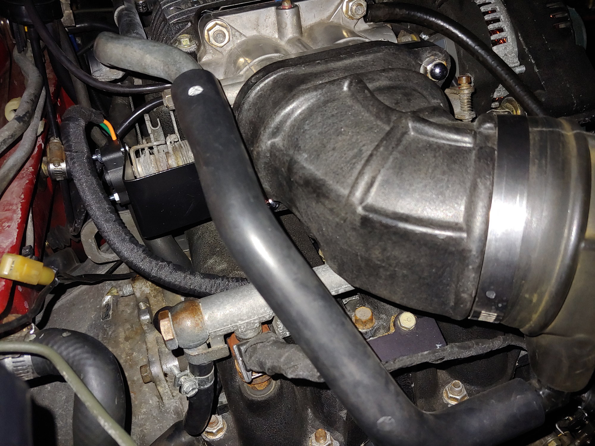
Step 1 was to remove the stock ECU and replace with MS3X + adapter:
Step 2: Run MAP sensor line and a fresh 10 gauge ground wire through the firewall grommet to the engine:
Step 3: Disconnect original ECU ground from top of engine and insulate it. Connect new ground in it's place:
Sorry, best photo I could get. The main ECU ground lives on top of the engine under the intake manifold.
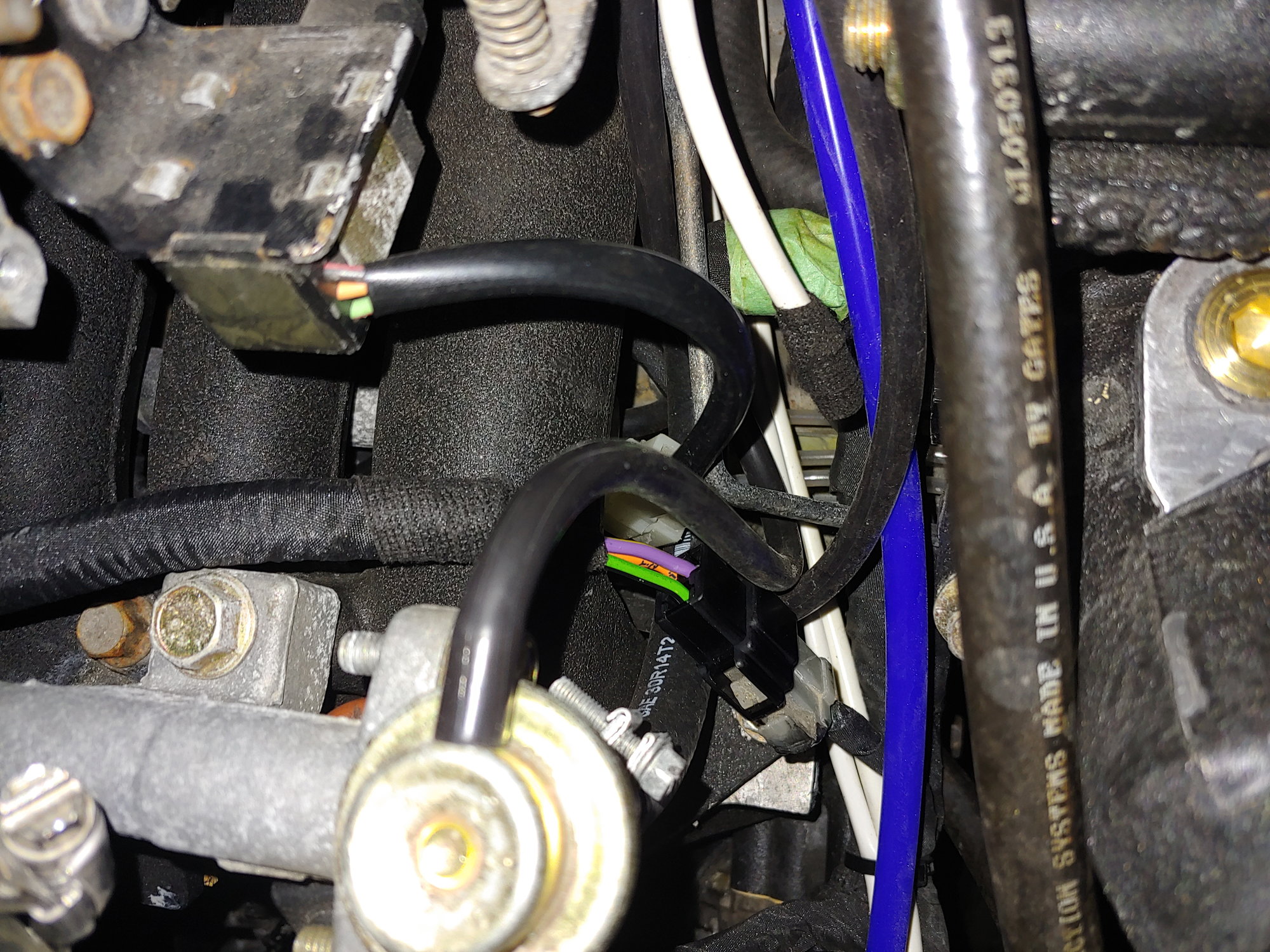
After that I was ready to start, but found I had no spark and no tach reading on the MS3X. I realized I had connected one pin wrong: One side of the MS3X CAS input was connected to the "Mileage switch" output on the stock harness instead of the appropriate CAS output. (Note: Mazda has a switch in the instrument cluster called the mileage switch, that trips at 20,000 miles. Nobody is quite sure what ECU settings it changes or why). It was a 5 minute fix, followed by 30 minutes of checking all the other pins. No other issues found.
Once that was fixed:
https://www.youtube.com/watch?v=UGHfCzpzyV8
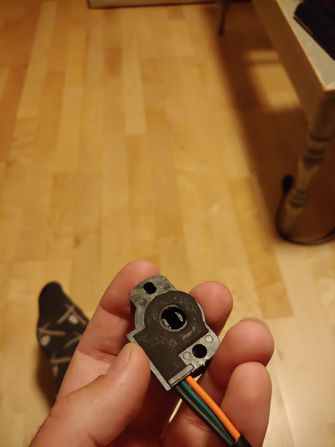
The next steps are to remove the thermowax and let the Megasquirt control idle with the BAC valve, and then to recalibrate the TPS. For some reason, despite including an idle valve, Mazda decided to implement the cold start high idle function mechanically. Right now the TPS calibration is off since the thermowax is physically nudging the throttle open when cold. I should have done this beforehand, but I like keeping things reversible as long as possible. After that I'll need to make some brackets and mount the ECU properly. For now I'm just going to sleep this cold off...
Until next time :)
One thing I noticed before I stepped away from the car yesterday was that the "lost sync" counter on the Tunerstudio dash was filling quickly. A "lost sync" is what happens when the MS3 expects to see the tooth in the CAS and doesn't. In about 3 seconds, it would max out at 300 and then overflow. That's a lot of lost syncs. Incidentally, the person who sold me the MS3 told me he also had a lot of trouble with the stock CAS, and he ended up just buying the Full-Function Engineering hall sensor & wheel. While it looks like a quality piece, I would prefer to save the $400 for something else. Let alone the fact that it would require modifying the whole belt-drive spacing to be able to run PS or AC. Rx7Club member Malic (who built a similar adapter) also provided some really helpful advice on avoiding lost-sync.
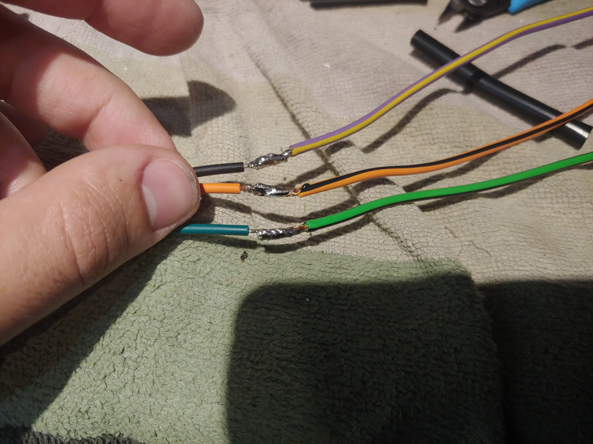
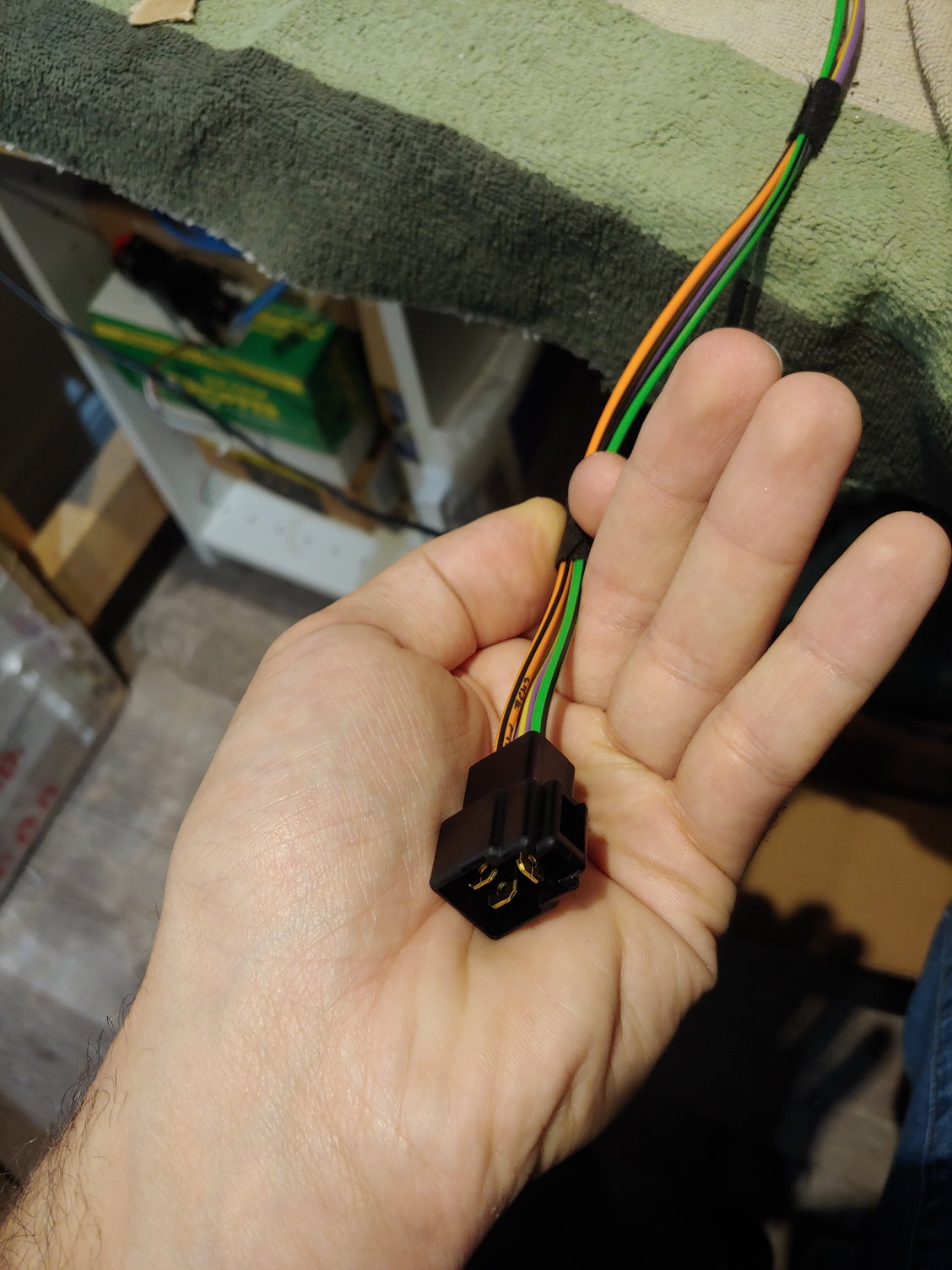
Anyways, the first suspect (as always) is the shield on the CAS cable. From the factory it has a pretty robust shield due to the very low output of the VR-based CAS at idle. I am of course using the factory harness, but I did have a spare 4-wire shielded cable around. Perfect for the CAS. I also have a spare CAS connector on the Turbo II engine I picked up, because the yard cut the harness and left all the engine side connectors:

There are two little tabs on the side that release a hinged section:
Which lets you remove the rubber seal:
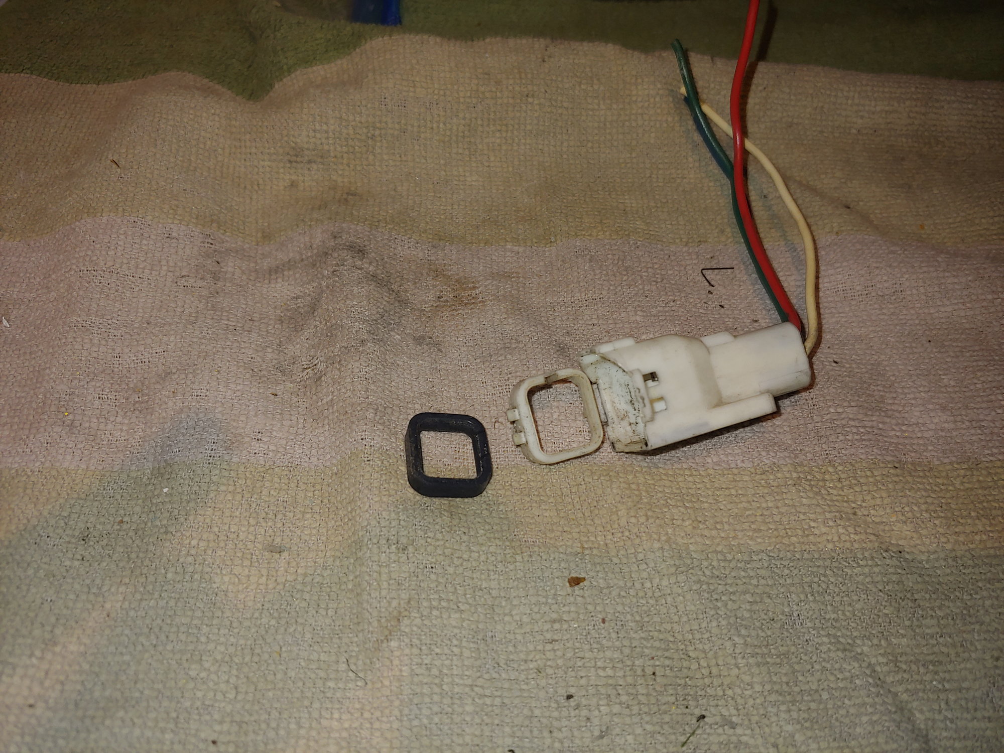
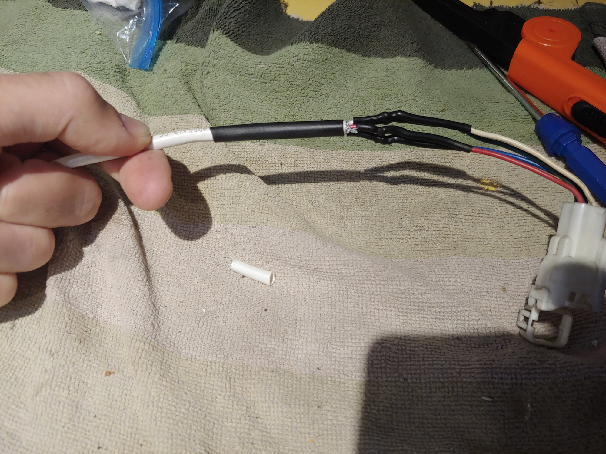
Then everything got a good scrub. It was oily and covered in grime (is there an Rx7 harness that isn't? ) but otherwise in very good shape. Then it was time to make the connections to the 4-wire cable:
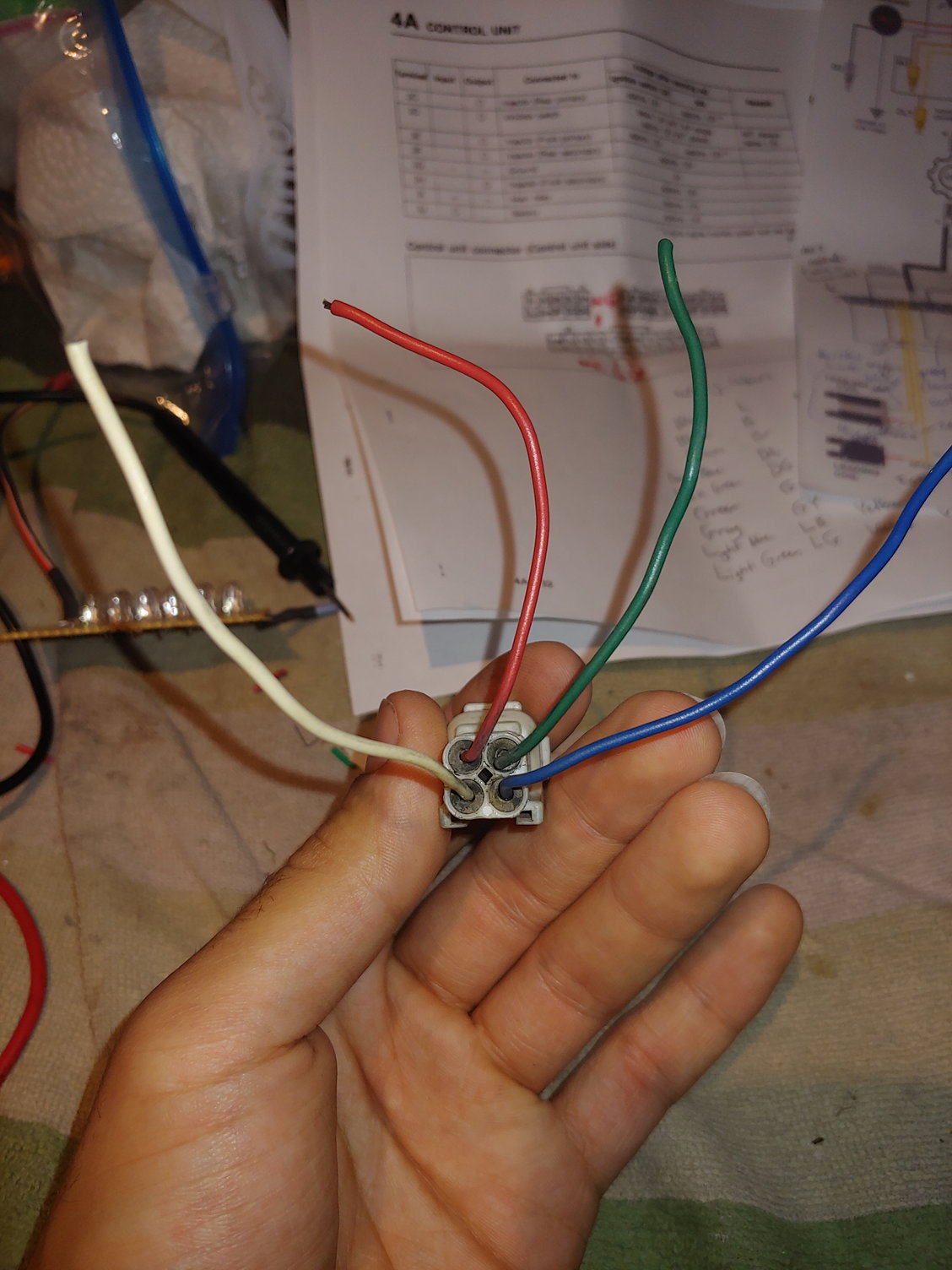
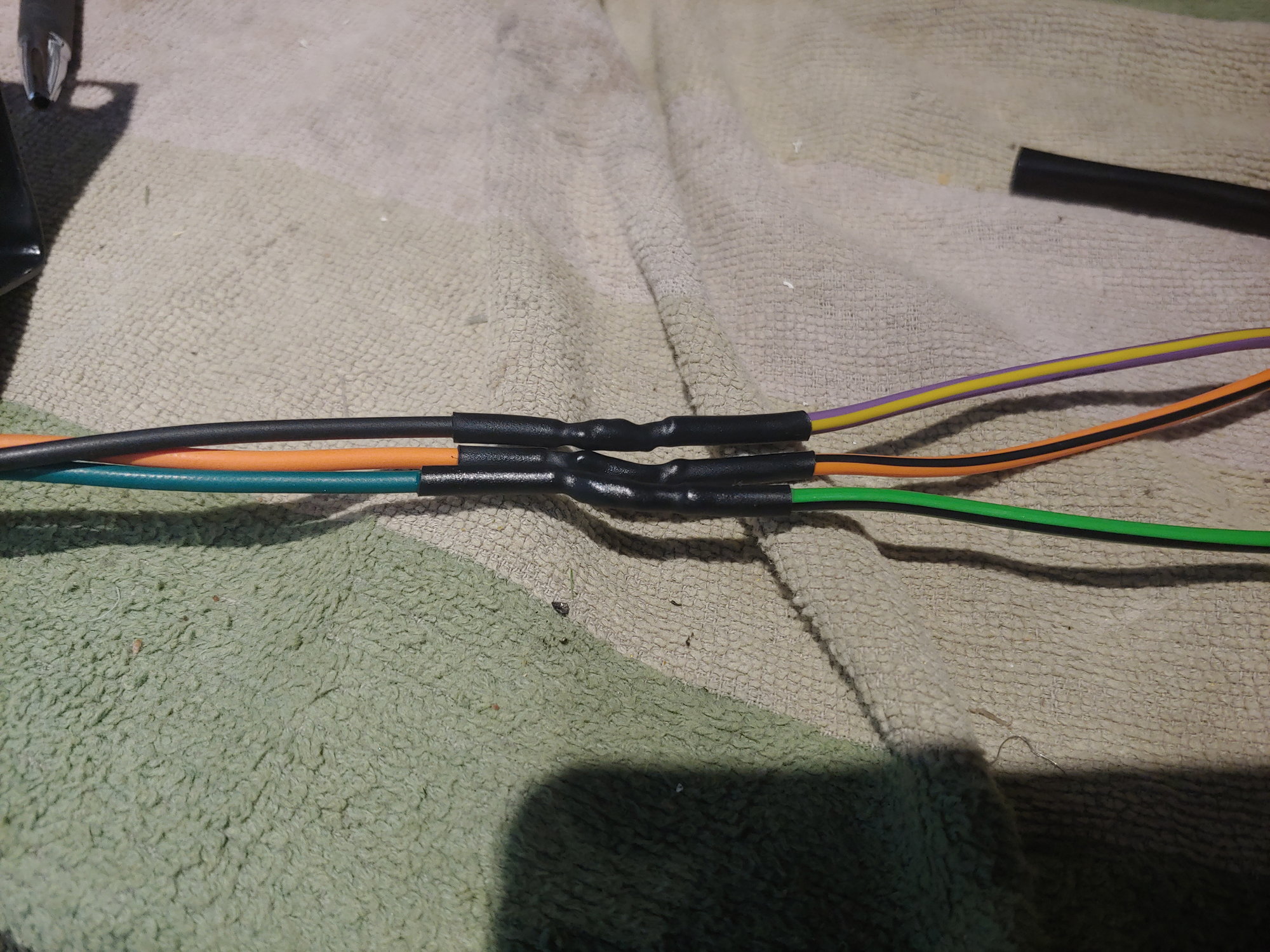
Conveniently, the colours are very similar. The only difference is the blue on the connector side corresponds to black on the cable side. Then everything got some nice marine heat-shrink to seal it:
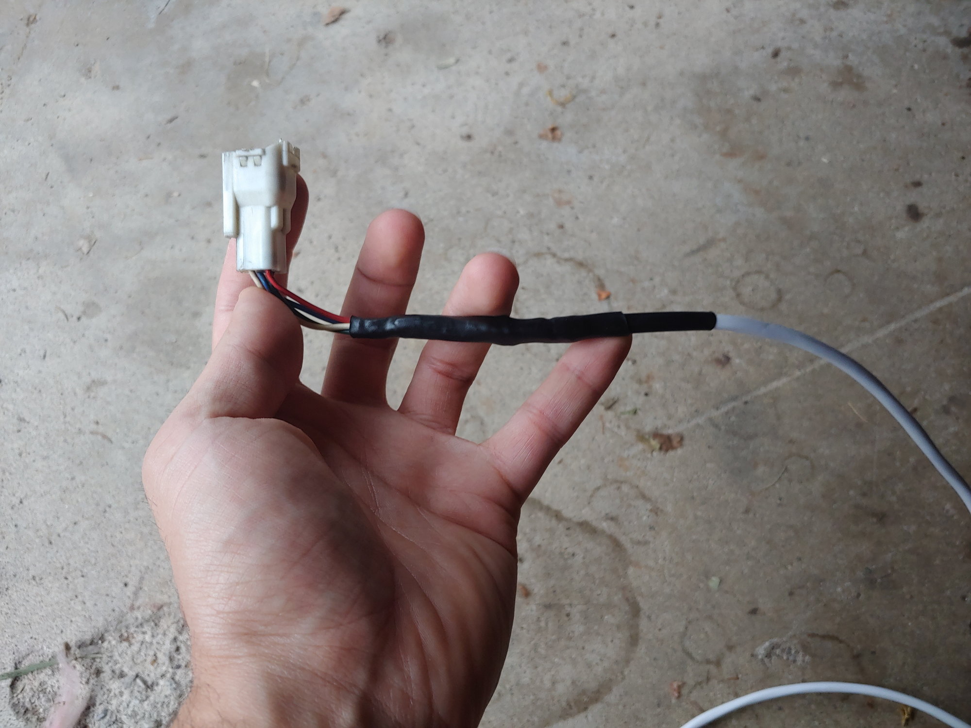
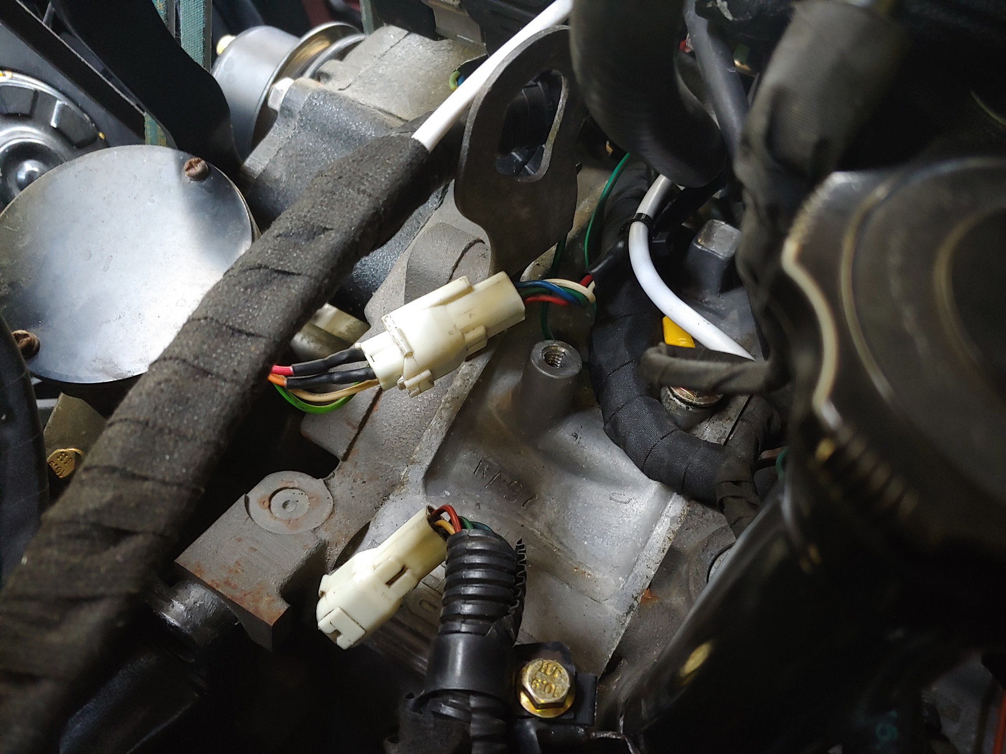
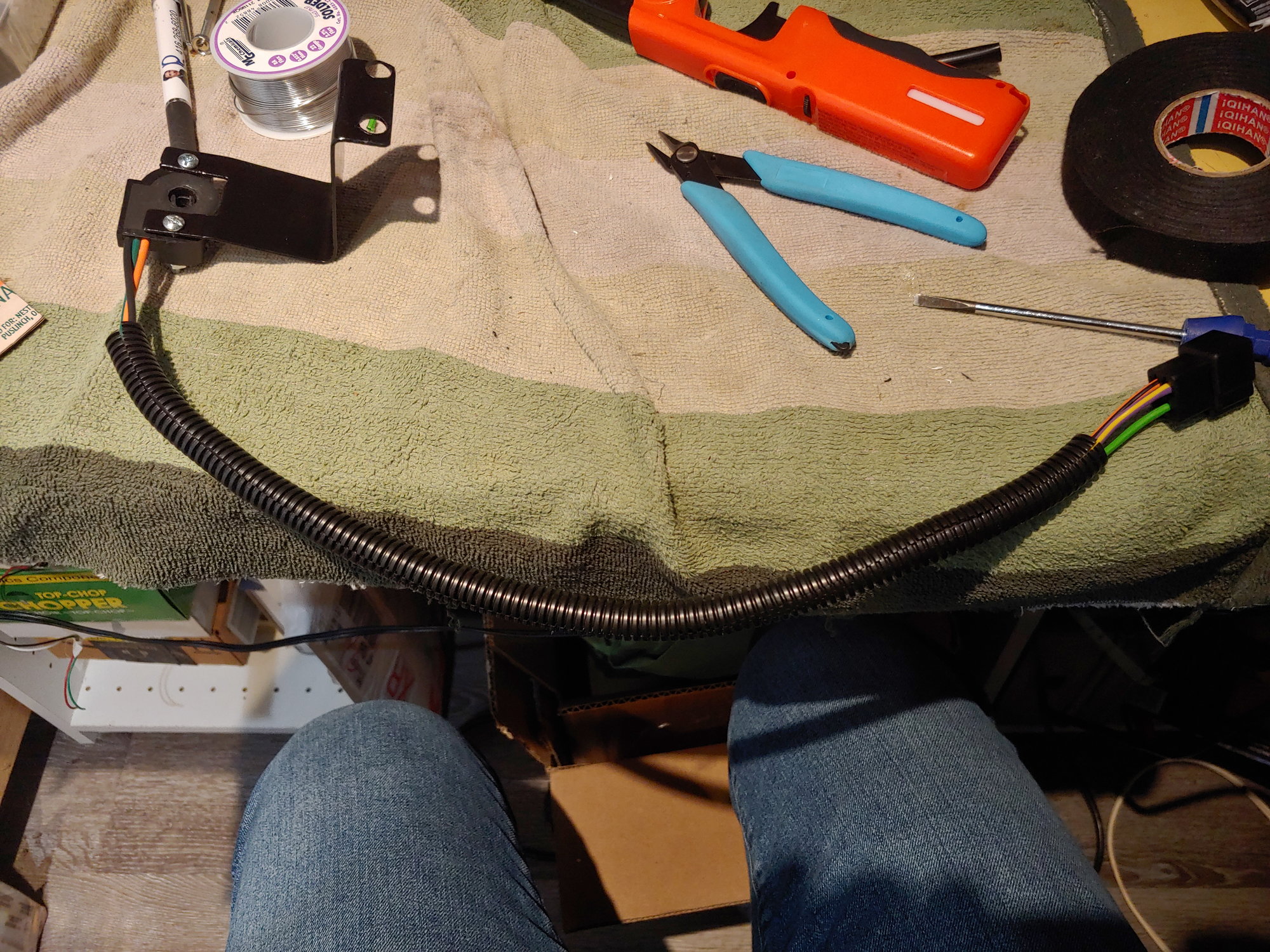
Then it runs along the engine harness into the cabin to meet the MS3. I'm quite happy with it. Except that Mazda decided to arbitrarily change the wire colours between Series 4 and Series 5... And that's ignoring that I replaced a cracked wire on my CAS with the orange one here awhile back. Luckily I connected the ECU end with bullet-connectors, so it was quite easy to swap them around. The shield gets one ground to the body by the ECU, and that's it.
After that I checked the sync counter again and found no improvement. I took a look at the composite log (the way MS3 shows you the crank / cam signals):

I'm no expert, but even I know there's a problem with that. Anyways, we'll get back to the log in a minute. I saw when searching that Aaroncake (Rx7 guru) suggested gapping the CAS pickups. He suggested the "thickness of a business card" which is around .020". Popping off the CAS cover:
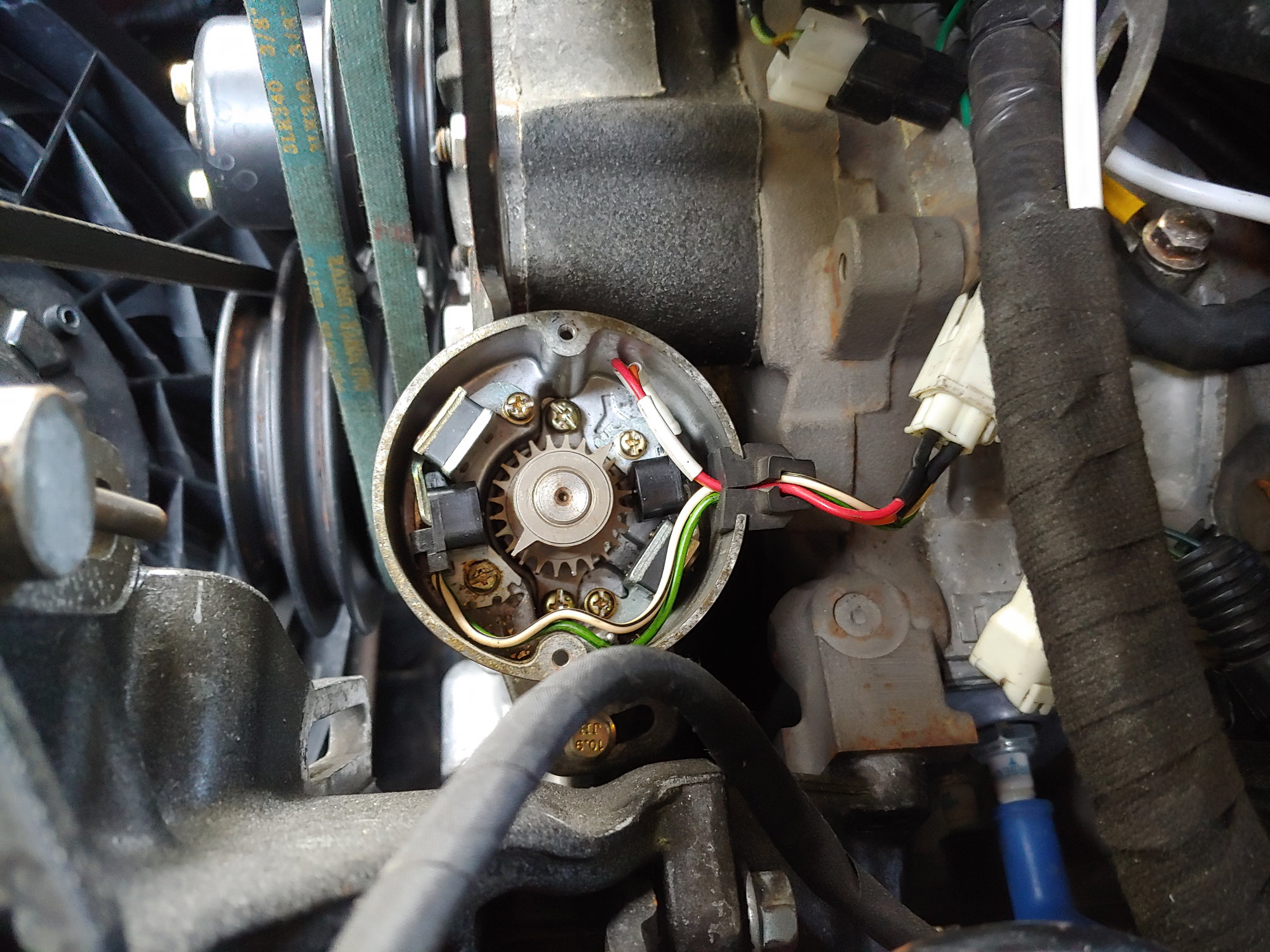
Loosening those screws let me use feeler gauges to adjust. I tried .013" first, and there was a bit of an improvement. But .020" was excellent. It completely removed the lost-sync issue when running at idle. Here's the same log after gapping:
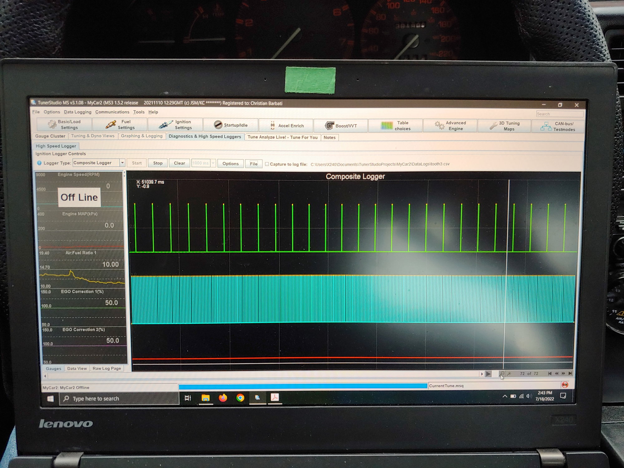
Rock solid. Sort of...
To be continued.
Continued:
I noticed there were a few conditions under which I still lost sync. When cranking, when the BAC valve saw duty, and when the e-fan activated. This was a fairly good indicator that I had a noise-related issue. I had already run a brand new cable, which should help minimize the issue. I made sure not to run it too close to anything noisy (like the alternator). One of the things Malic mentioned though was that the potentiometers in the MS3 may need adjusting, and he sent me a link that explains it pretty well for a layman like me.
There are two potentiometers. By default they should be turned all the way counterclockwise according to Aaroncake's excellent guide, but under certain conditions they do need adjusting. In my case the hysteresis pot can be used to help filter noise. So I removed the top case from the MS3X and tried adjusting:
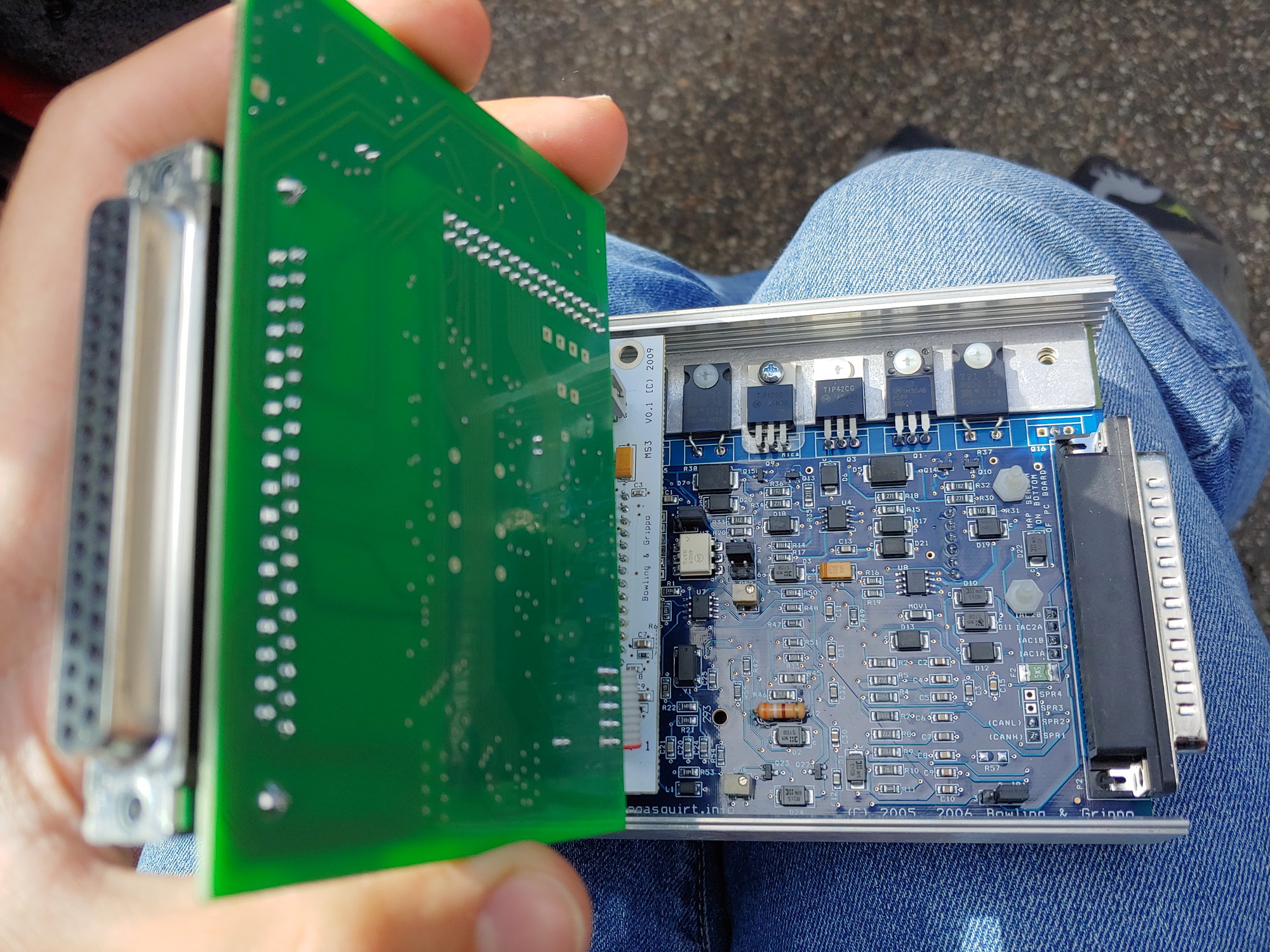
It's the tiny beige box with a screw on it, on the bottom right. I tried turning clockwise a half-turn at a time. I thought there might be an improvement, but after a long (and tedious) time I realized it wasn't doing much if anything. But then I remembered something; Here's that log from earlier:
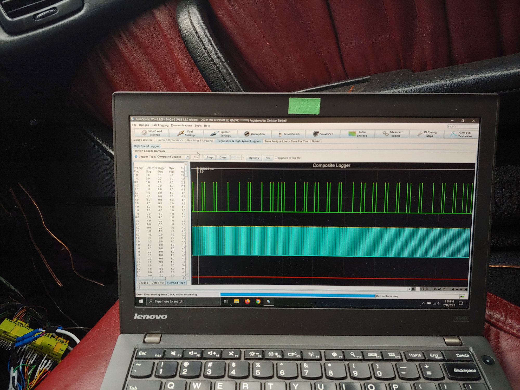
The blue signal is the crank, which is connected to the VR input on the MS3 Mainboard.
But the green signal, with the obvious problems, was the cam input. This is on the VR input on the MS3 Expander board. Instead of adjusting the pot on the blue circuit board, I should have been adjusting it on the green circuit board. After about 2.5 turns, the problem completely went away. No sync loss when idling, when blipping the throttle, when cranking, or any other time. I may need to fine-tune it some more once I actually drive the car, but for now it's fixed.
The next job was to remove the now-redundant thermowax:
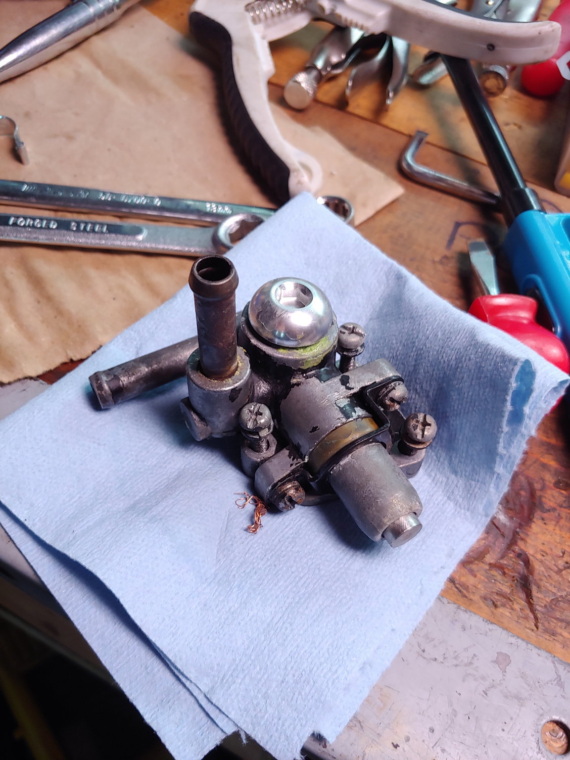
Mine was already modified a bit when I removed the secondary throttle blades. Now it's functions can be entirely replicated using the MS3 idle control system. Conveniently I put some RTV on the black plastic plate that sits under the thermowax, so it already seals the passage and I don't have a vacuum leak. I'm going to cut down the thermowax mounting bolts and use them to hold the plate in place permanently.
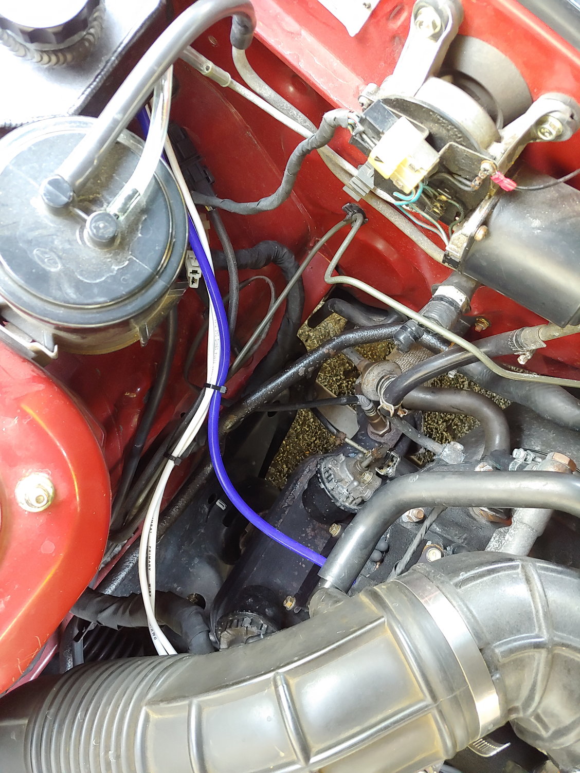
Then I had to reroute the coolant hose that used to go to the thermowax. It could be deleted entirely by capping it and the return nipple on the water pump housing. However, clearance for the nipple on the housing is tight, so I decided to just leave it as-is. This means that the coolant from the rear nipple still needs to reach the front. Simple enough:
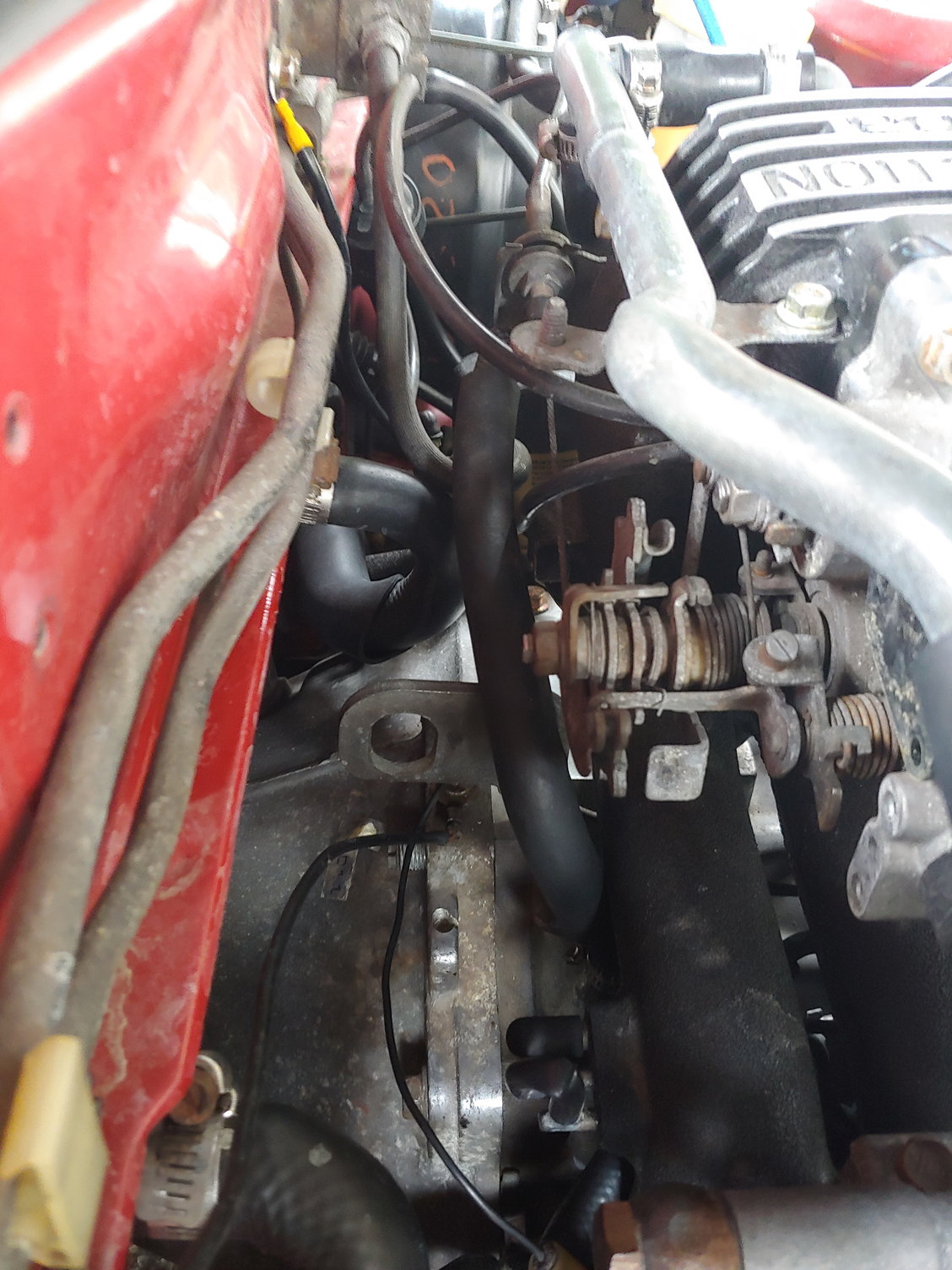
Done. Mazda apparently ran the hose along the BAC valve to prevent icing. Not sure if that's a real problem but for now it'll still have it's coolant feed.
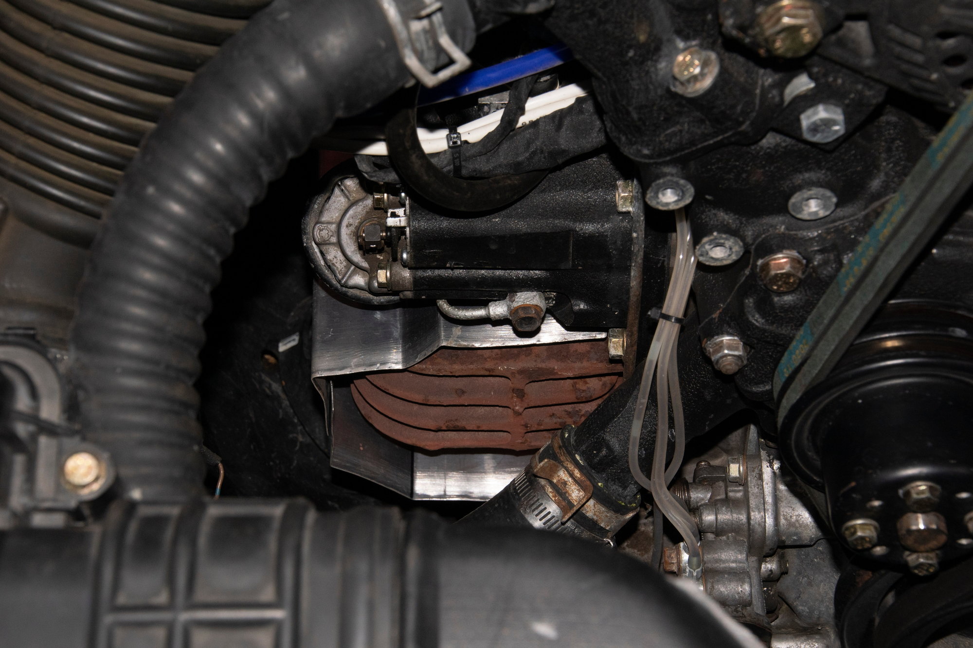
I also removed this thing. I know Mazda has a name for it, but I always call it the "big air solenoid". It behaves sort of like the BAC valve, except I think it's a simple on/off type valve. It's used for heavier engine loads like power-steering, but the MS3 again renders it redundant:
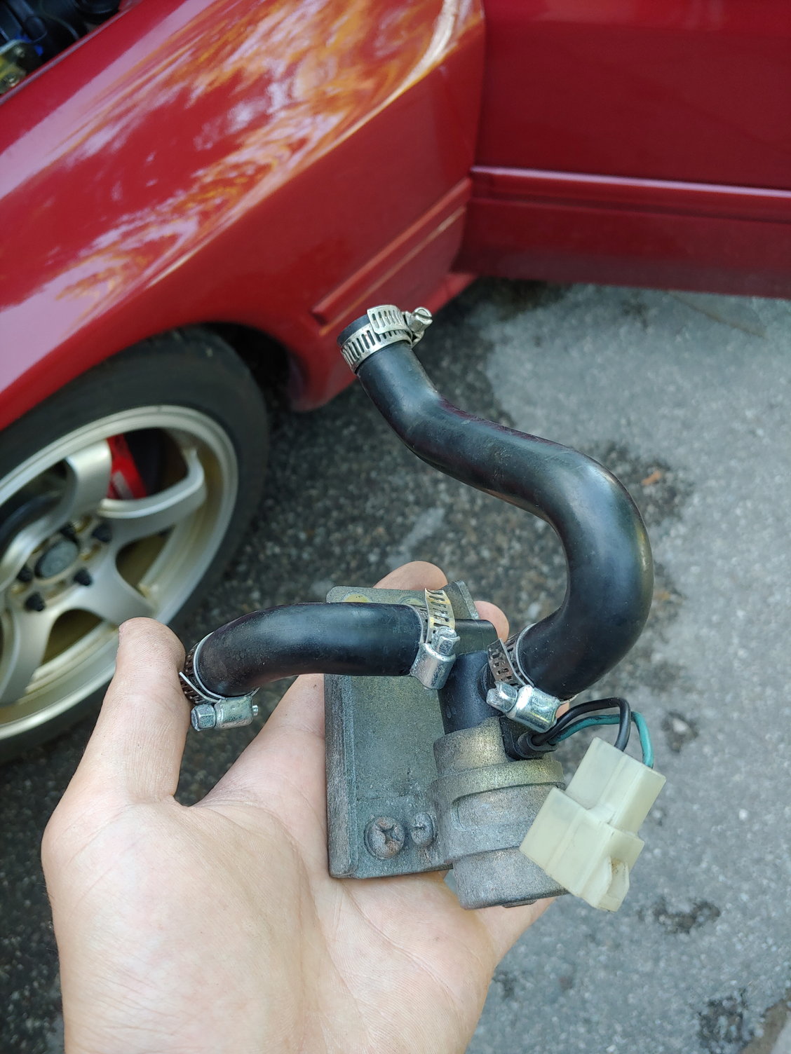
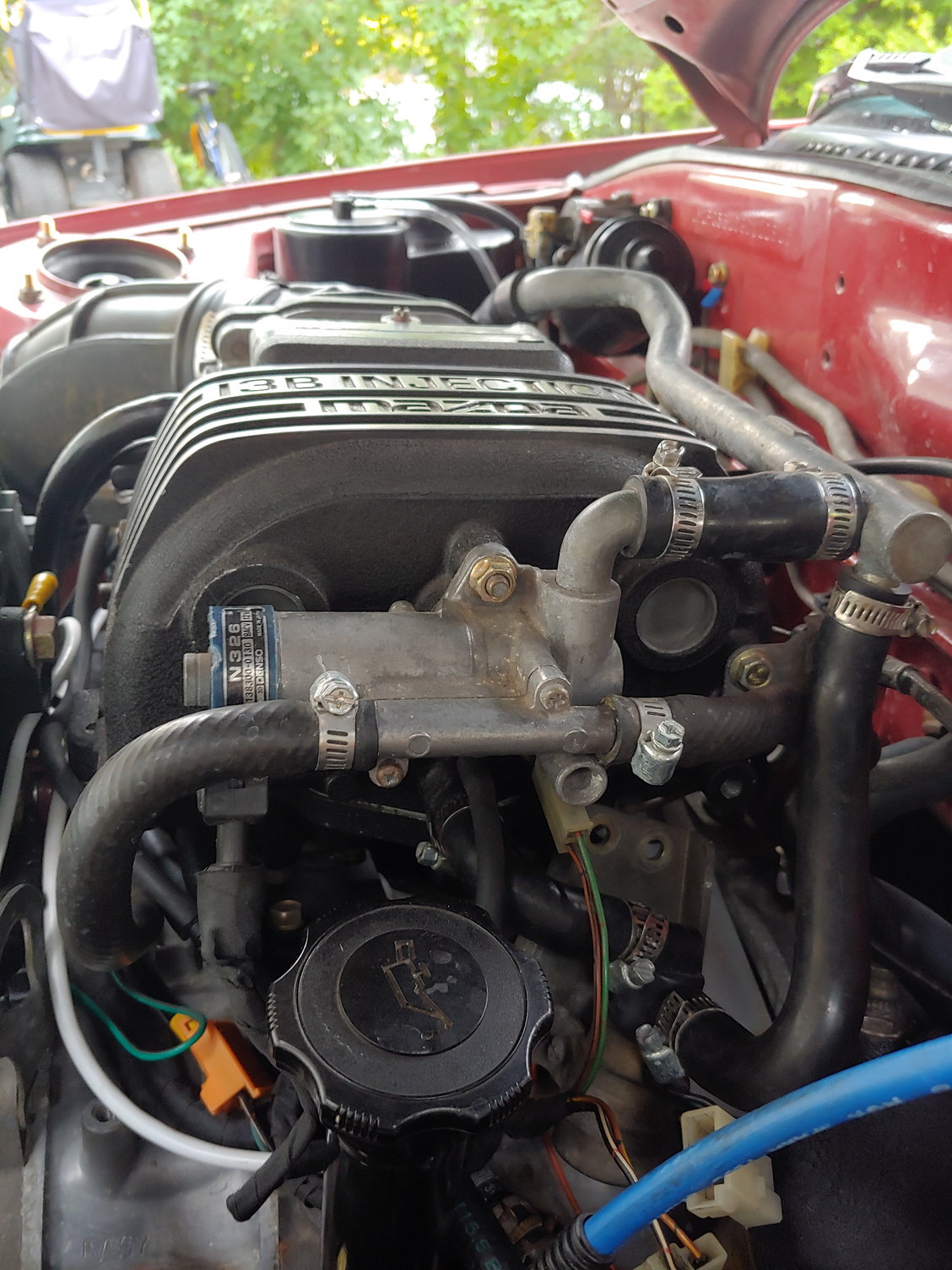
The air supply nipples were capped off, and then I did some more neatening up in the area:
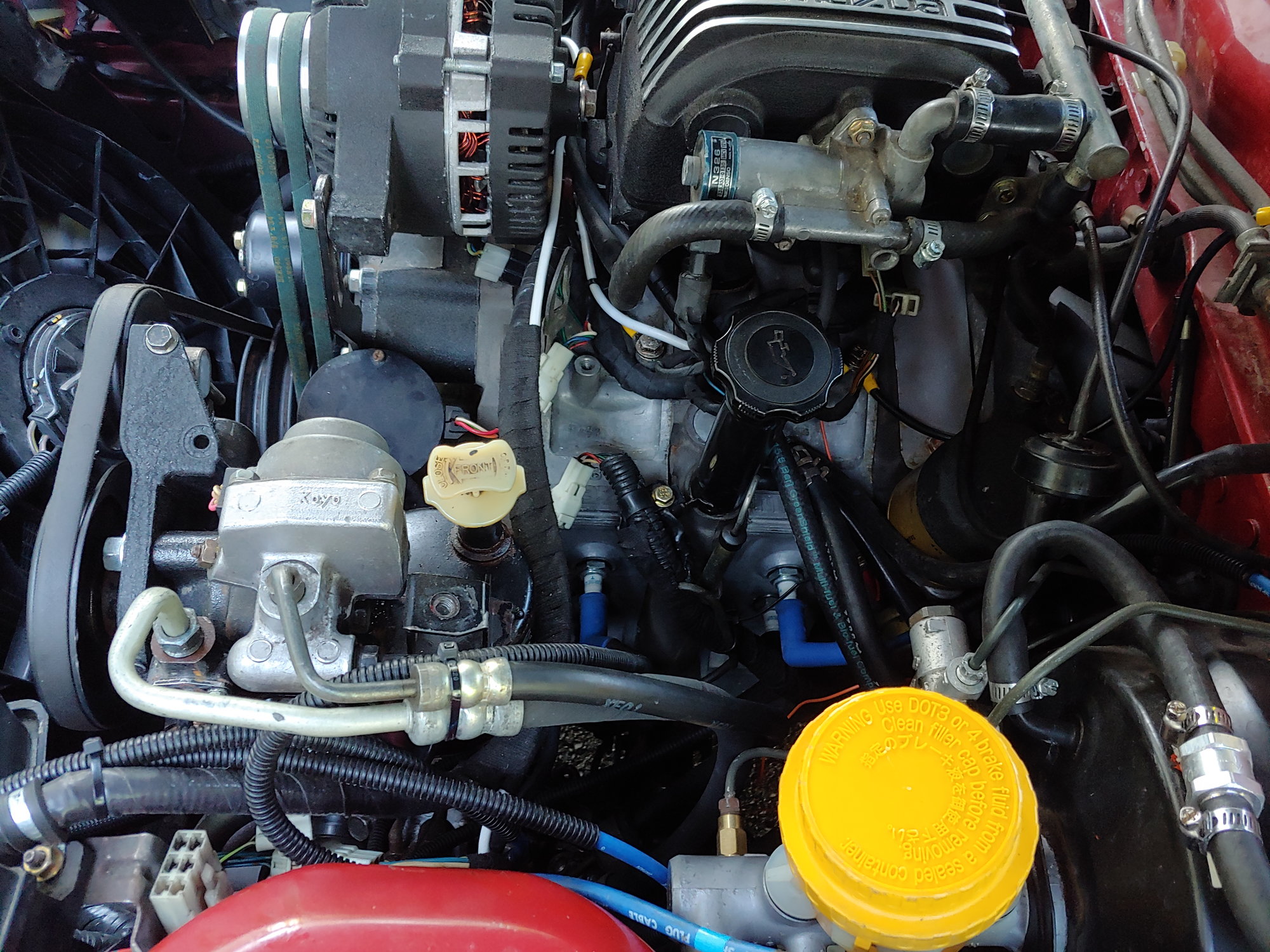
If the spark plug wire routing looks a bit unusual, that's because it is. One side-effect of Mazda's love-affair with bracketry is that everything really only wants to fit one way. The leading spark plug wires are really long because they used to clip to the coolant expansion tank, for example. Conveniently since the leading is a waste-spark setup I can just zip-tie them together and forget about it. I had to be careful to route the trailing wires farther apart.
A couple zip-ties vastly improve the new wiring I've run. Not perfect, but presentable.
Not presentable, however, is the inside of the car:
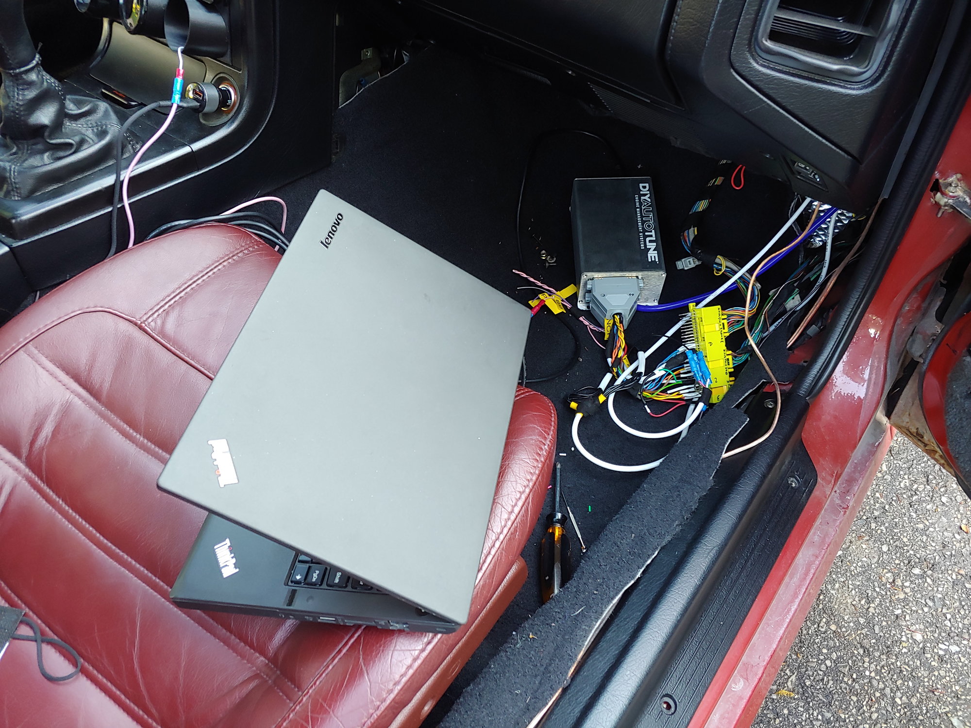
So that's the next thing I'll be tackling.
Until next time :)
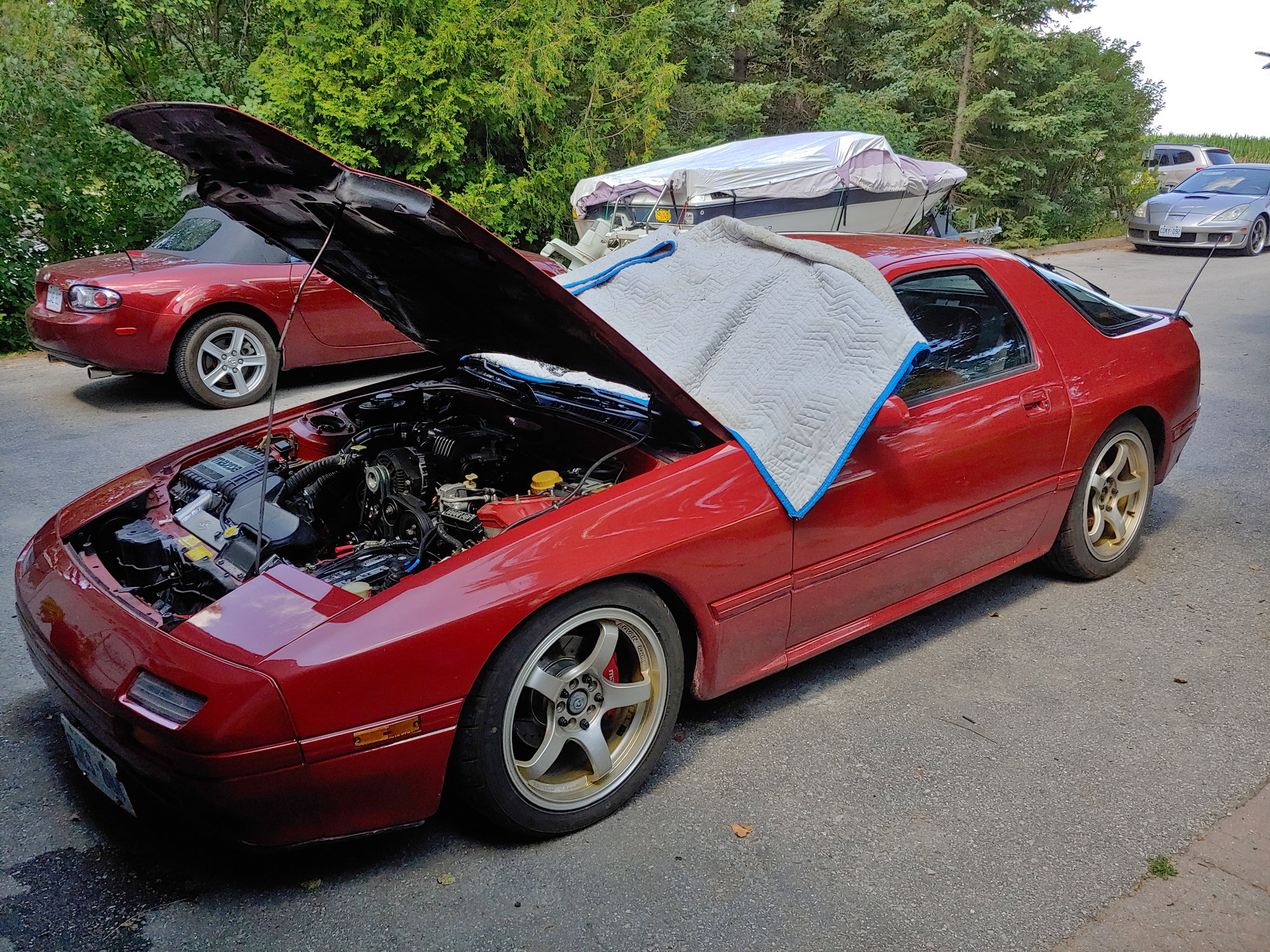
The heat the past two days has been oppressive. My area doesn't actually get that hot (I think it was 33 C yesterday), but it tends to get quite humid which makes it quite stuffy. This is aggravated when you're working in the cabin of a sports-car with a glass hatch and no window tint. A moving blanket over the windshield makes it about 1% better.
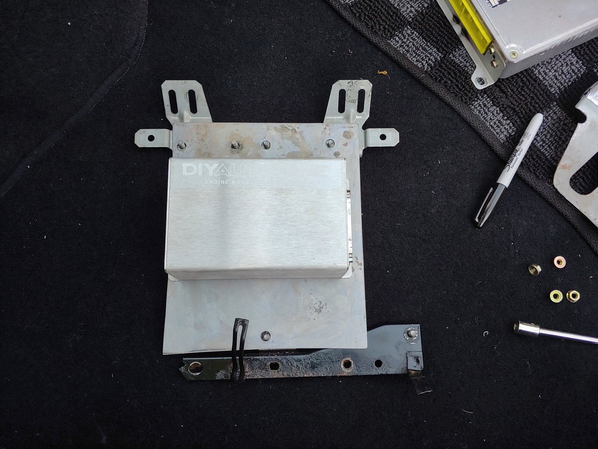
Before driving the car, the ECU had to be mounted solidly. Taking a look at the stock ECU bracket, it gives us a few options. I chose the one that felt most logical:
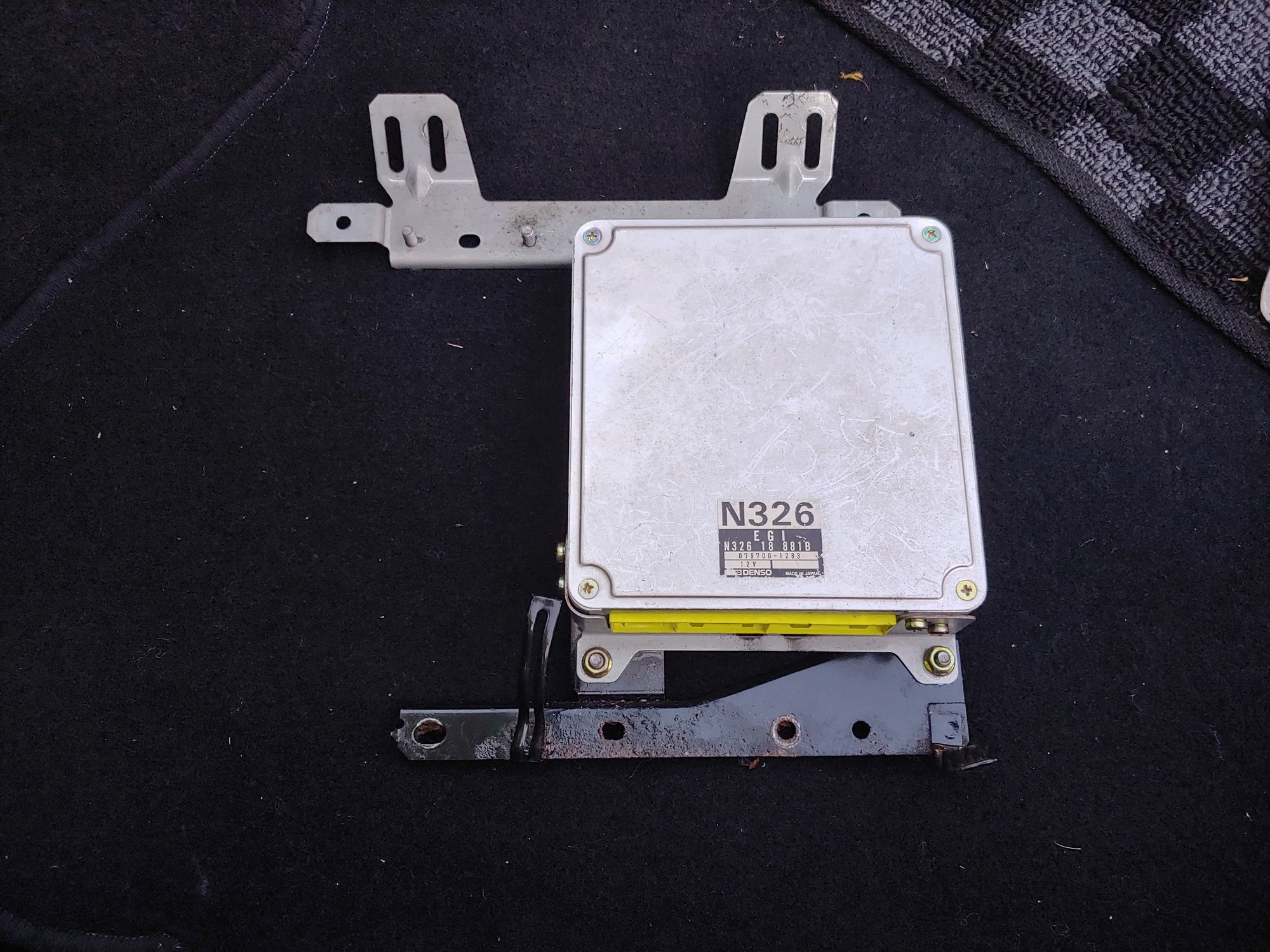
The stock orientation puts the connector at the bottom. The harnesses then make their way down before curling up to meet the ECU. If I were to mount the Megasquirt in this orientation, the adapter would make it impossible to stretch the stock harnesses to meet it due to the added length.
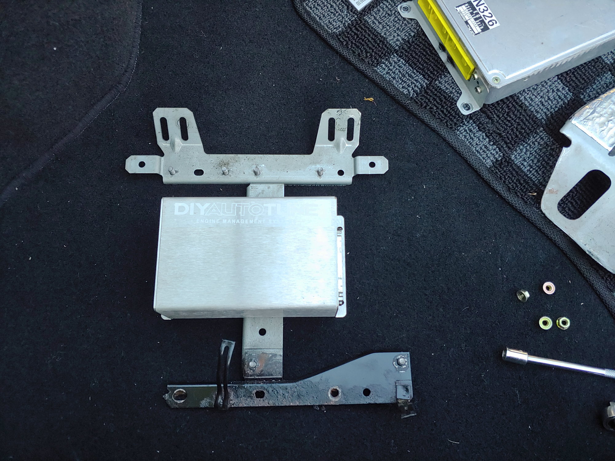
So instead, I mounted it with the DB37 connectors facing the right. Positioning it further left on the bracket gives me clearance for the adapter, and there's plenty of space on the left for the USB connector still.
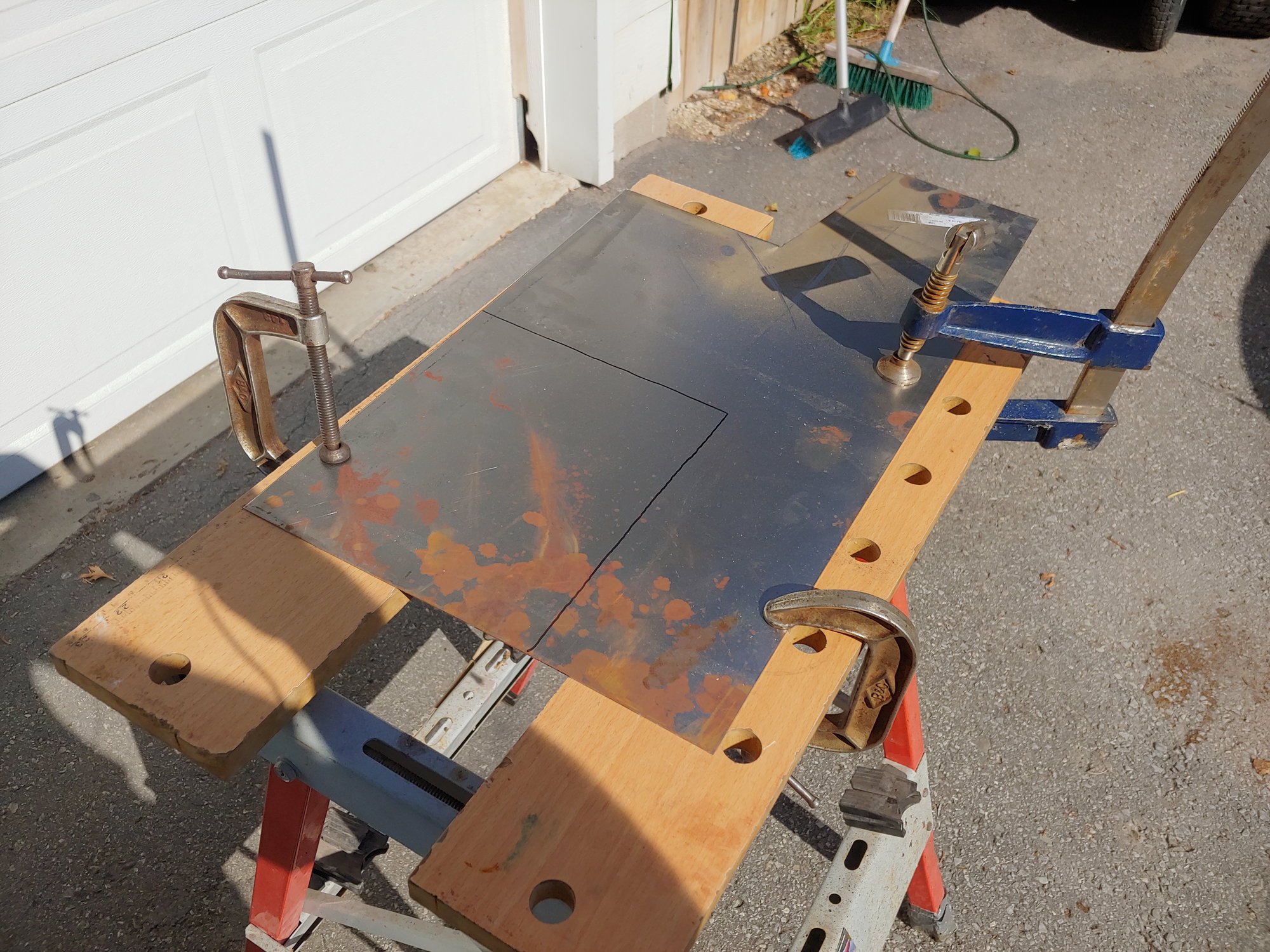
I made a cardboard template and transferred that to a piece of sheet steel:
Drilled the mounting holes and did a test-fit:
After that it got a coat of paint. While waiting for it to dry, I decided to neaten up the wiring a bit. I had stripped back some of the stock harnesses while investigating the sync issue, so it was time to re-tape them:
While I'm in here, anyone know what that grey box does? I've never seen it on a diagram.
I'm going to have to revise this a bit in the near future, for two reasons. First, there's a lot of extra length in the CAS wiring and the Megasquirt ground. I'm out of the necessary connectors so for now I'll need to leave it as-is. Second, the kick panel that fits over the ECU doesn't bolt down due to the height of the Megasquirt case. It floats on the studs and is quite secure once the carpet is down, but it's not a proper solution. I can't use washers as the top & bottom mount holes are at different angles, so I can't space out one without rendering the other useless. I will need to make a new case for the MS3X that is shorter, mount it in a different location, or find a way to modify the kick panel without leaving the ECU exposed to bumps from the passenger's feet.
The last thing I did yesterday was wire the electric fan to the Megasquirt instead of the coolant switch I was using before. I have it set to turn on at 195, off at 185. This is a lot better than the 185/175 of the switch I was using.
Then today I was able to get out there and do some tuning. I had a few obstacles though. The Series 4 TPS is narrow-range, which makes the accel-enrichment less than ideal. Going to play with the MAP-dot based enrichment a bit since the narrow range TPS doesn't acknowledge throttle openings greater than about 25%. I do have a full-range TPS in my basement somewhere that I purchased to try and retrofit, so I'll have to dig that out soon.
I also had some trouble getting a consistent idle because the throttle cable was over-tightened, which meant it wouldn't consistently end up at 0% TPS. Consequently the amount of air at idle was different every time I let off the throttle. After a few minutes adjusting it, I have that fixed.
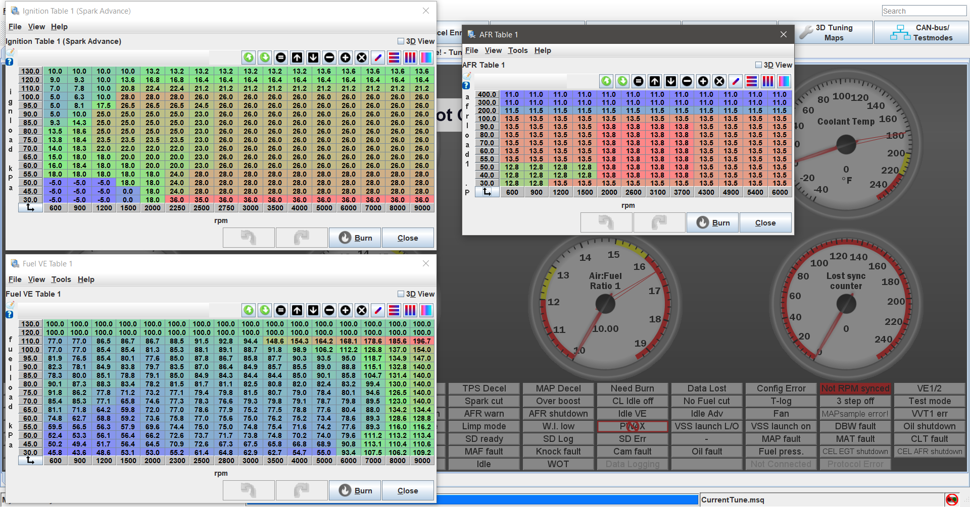
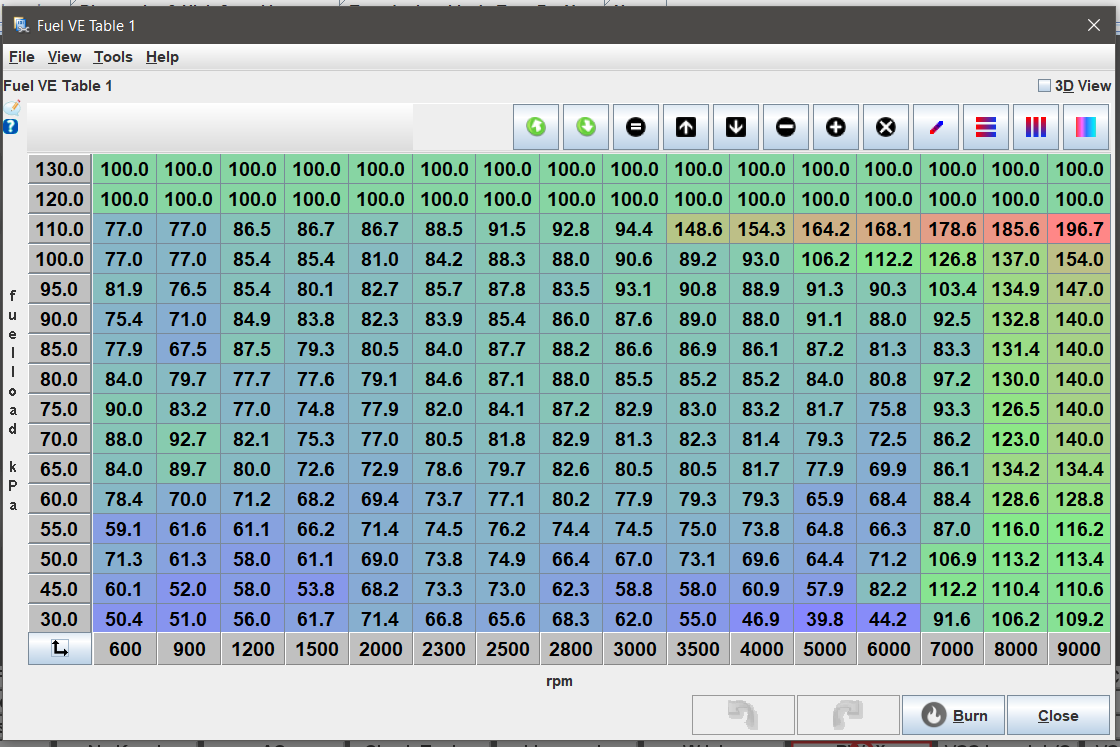
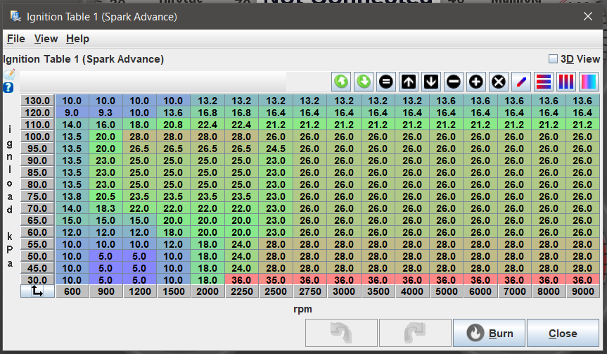
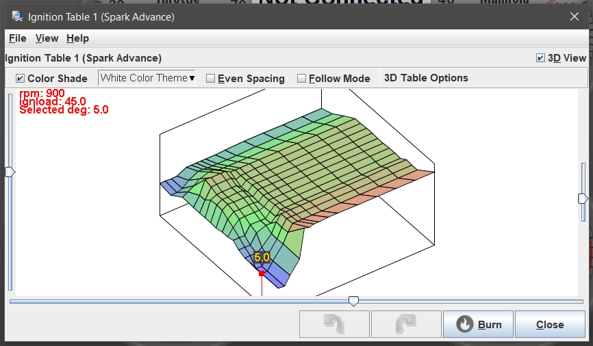
I was starting from Aaroncake's base maps, and I found I had to do a lot of adjustment. While it was rich at high rpms (to be expected), I had to add lots of fuel in the idle and mid-range. I think this may be a quirk of the way engine size is defined in the version of Tunerstudio that Aaron used to make the maps vs. the current version. I also found that the provided timing map was fairly aggressive and I saw pretty high coolant temps, so for now I've pulled some out. Especially at idle, where the base map was running +18 degrees of advance (vs. the stock ECUs -5 degrees). I put it back to the stock idle timing since that gave me the smoothest idle (some table smoothing will be required). His maps also had cruise at 14.7-15.2 AFR, which seems high to me. I'm thinking that might work better with the sequential injection tuned properly, but for now I'm targeting richer mixtures like the stock ECU ran.
I did try letting the autotune do it's thing a bit, but noticed it was almost universally richening the cells above idle. So tomorrow I'm probably going to try saving a backup of the current tune, richening the whole map, and then leaning it out from there (whereas right now I spend my time richening). Lastly, despite having a nice solid idle, the moment I try to enable closed-loop idle control the idle starts to oscillate more and more before the car eventually dies. Changing the PID values does not seem to help. Going to take some datalogs and investigate from there, but for now this means the dashpot function doesn't work either and the car will occasionally die when shifting into neutral for a stop.
Overall though the car drives decently. I have to iron out some of these wrinkles, but if I wanted to drive the car to work or for groceries I would have no problem doing so.
Until next time :)
With some help from Rx7Club member Shaniac (thanks again!) and using his maps as a reference, I've made a lot of progress today. I spent a lot of time on the idle and figured out the closed-loop issue. All I had to do was add a few degrees of advance below the idle bins to "catch" it, and richen the high-vacuum row along the bottom left as well. I added timing across the whole idle area just to make the transition smoother, and I found that since I got the VE table more dialed in the added advance doesn't hurt the idle as much. The closed-loop idle control is working really well now. I haven't played with the closed-loop advance but it's something I'm going to look into. Using the 3D view was also a really helpful tip; it definitely helps visualize the transition from bin to bin:
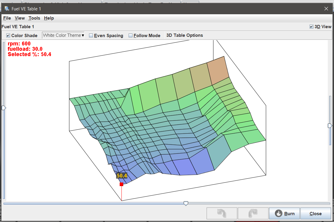
The peaks and valleys on the extremes of the graph are because I have yet to touch some of the bins. For example, I have it mapped to 9000rpm but have yet to take it past 7000 (no real reason to on stock ports).
The dashpot function proved unnecessary after I neatened up the idle bins, but I left it enabled just to enhance driveability. I also found that blending MAPdot and TPSdot at a 50/50 ratio got the accel-pump working very well. Overall it's driving really well now. Starts right away, idles better than the stock ECU ever did, and it feels like it may have picked up some power as well.
The only thing I notice is that it runs hotter on average than it did on the stock ECU. I'm still running on the rich side, cruising around 13.8, but for some reason it's hovering around 90C (194F). When I really get into it, it sometimes got as hot as 95C (206 F). On the stock ECU cruise was around 84 C, extended WOT around 91 C. Not sure what's causing this since the timing I'm running is less aggressive than the base map (and Shaniac's map). Going to have to investigate further, but I'm not really worried as long as it doesn't cross 100 C. This does however make me reluctant to try leaning out the map any further.
Until next time :)
I checked my datalogs and found that there is a discrepancy between the internal temperature gauge reading and the reading from the ECU. While the internal gauge showed peaks of 97C (207F), the ECU logged a maximum of 198F (92C). Given that my internal temperature gauge is a $40 eBay part that's about 5 years old, I'm more trusting of the ECU sensor. I'm also running Shaniac's timing map (with timing pulled at idle to keep it smooth), and everything feels good so I'm just going to leave it for now.
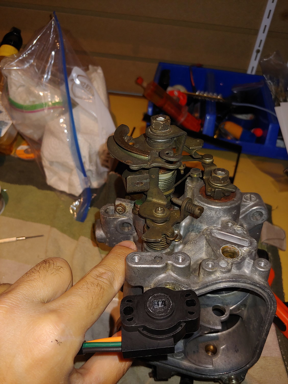
Yesterday night (forgive some of the flash photography) I worked on the full-range TPS conversion. I'm using the same Mustang TPS as most of these conversions use, but I wanted to make my own bracket rather than purchasing one. I first thought about replicating some of the brackets I see online and locating the TPS on the front of the throttle body, like stock:
But it's a bit crowded here. Now the commercially available brackets seem to use a small adapter that fits on the end of the shaft, and then locate the sensor further out to clear the OMP linkage. However, I have a large Taurus alternator there. So I asked myself, why locate it there when I have more space here?
The back of the throttle body has lots of space, since the dashpot and thermowax are eliminated due to the standalone. The TPS is designed to be rotated only in the one direction, so we need a small adapter piece:
It drops into the side of the TPS that normally fits over the shaft:
Then allows the "back" side of the TPS to accept the throttle shaft:
Looking at the mounting options on this spare throttle body, it's actually pretty easy. The center of the dashpot mount is directly in-line with the throttle shaft, so we just need a flat rectangular piece of steel with some minor bends:
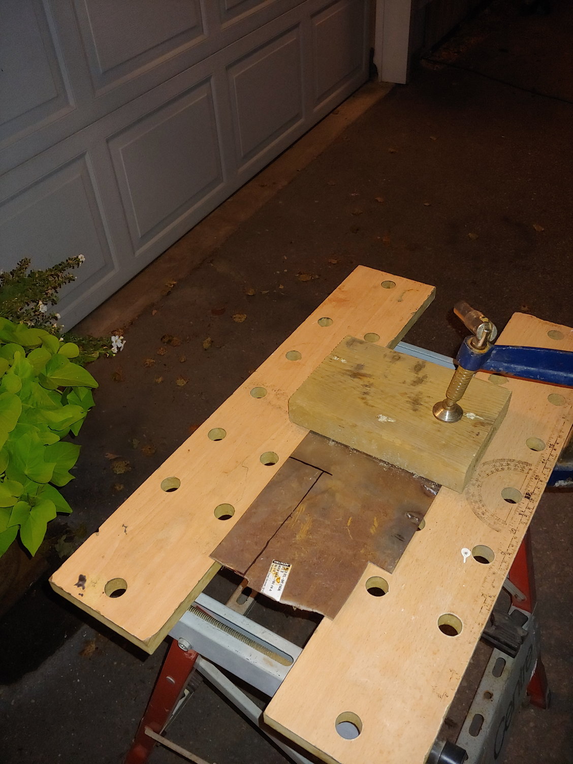
Cutting and bending the steel at midnight (we have plenty of space between us and the neighbours, so hopefully the angle grinder didn't wake them):
Then notched it to fit the sensor, drilled the mounting holes, and painted it:
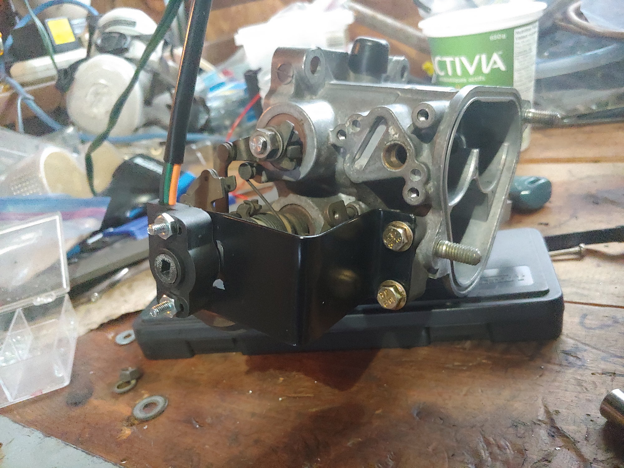
There we go. Full-range TPS without deleting any factory functions (that wouldn't be already deleted with the standalone). And it doesn't interfere with the Taurus alternator.
I have yet to actually install it though, since I currently have the accel-pump function working quite well and don't want to mess with it yet. So for now I'll put it aside until I have a few hours to mess with the settings.
Until next time :)
I've been working on some small things lately, none of which lend themselves well to pictures. Neatened up the tune a bit, but it's working well enough that I can get in the car and not think about it. Adjusted the hood latch so it no longer tries to pop open while driving (only when going over a really big bump, but still, a major safety hazard). Chased down a few interior rattles. There are two improvements I've made which are worth documenting though.
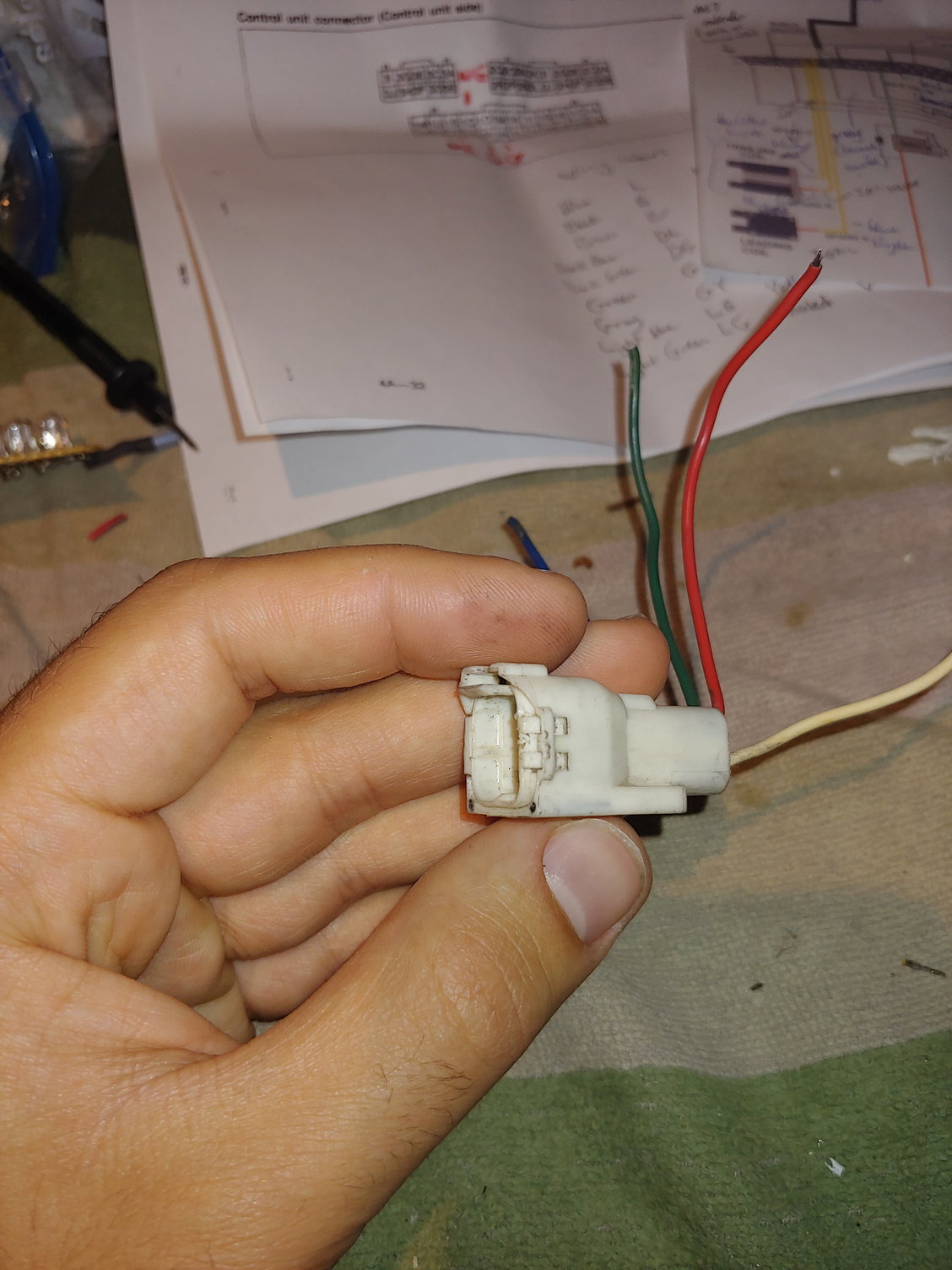
First, I finished the full-range TPS conversion. When we left off, I had finished the bracket and adapter for the throttle linkage. The next step was to extend the wiring, since I've installed the TPS on the other side of the throttle body:
Conveniently I already had the necessary 3-pin Yazaki connector:
A piece of split-loom tubing to protect the wiring:
And then some tape to hold it all together:
I had a good think before deciding how to wrap it. I didn't bother wrapping the new Megasquirt ground or CAS cable, since both of them will be integrated into the new harness once I swap in the 13BT. This sensor deserves more attention since I will only be changing the connector to match the new harness, and possibly shortening the wiring depending on the routing. The split loom is because this wiring runs over the intake runners and fuel rail, so it provides some abrasion protection. The tape on the outside of the split-loom is TESA engine harness tape. Electrical tape is not ideal as it becomes sticky with heat. Silicone self-fusing tape would probably be better than the TESA tape to prevent fluid ingress, but being frank, I just hate the way it shines. I re-wrapped most of the body harness in the engine bay with the silicone stuff and it bothers me every time I see it. Then I used the fuzzy interior harness tape on the ends, as I find that it sticks better and doesn't come unravelled at the ends like the TESA engine harness tape. When I make the new engine harness I am going to investigate that nice woven mesh sheath that I see people using.
After spending far too much time pondering wiring harness tapes, installation took less than five minutes:
If you're wondering why I didn't mount the TPS upside down to make the wiring neater, it's because there's a hump in the side of the TPS facing away from the camera. When flipped this hump interferes with the bracket and causes the TPS to sit sideways on the throttle shaft. Notching the bracket would remove one mounting ear, so it would necessitate a new bracket with a different design. And frankly, this one is good enough for now. I have a container full of little harness p-clips, but I've misplaced it. For now I'll let the wiring float. There isn't enough length for it to flap around much.
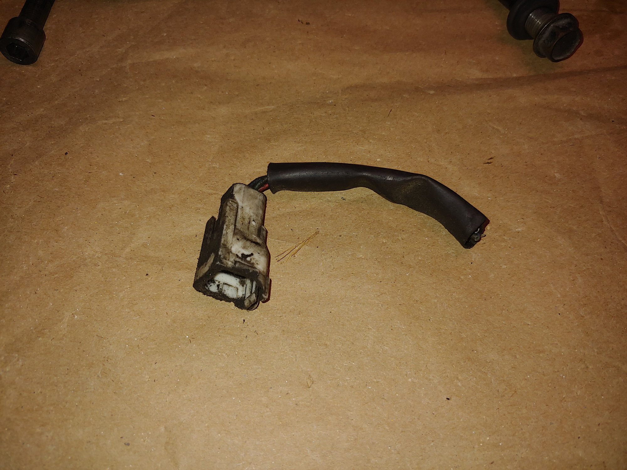
I left the old TPS connected for now. As you can see the harness-side connector has been through a lot in it's life:
I have the new connector, but I'm going to leave well-enough alone for the time being. This whole area is going to receive some much needed TLC with the new harness.
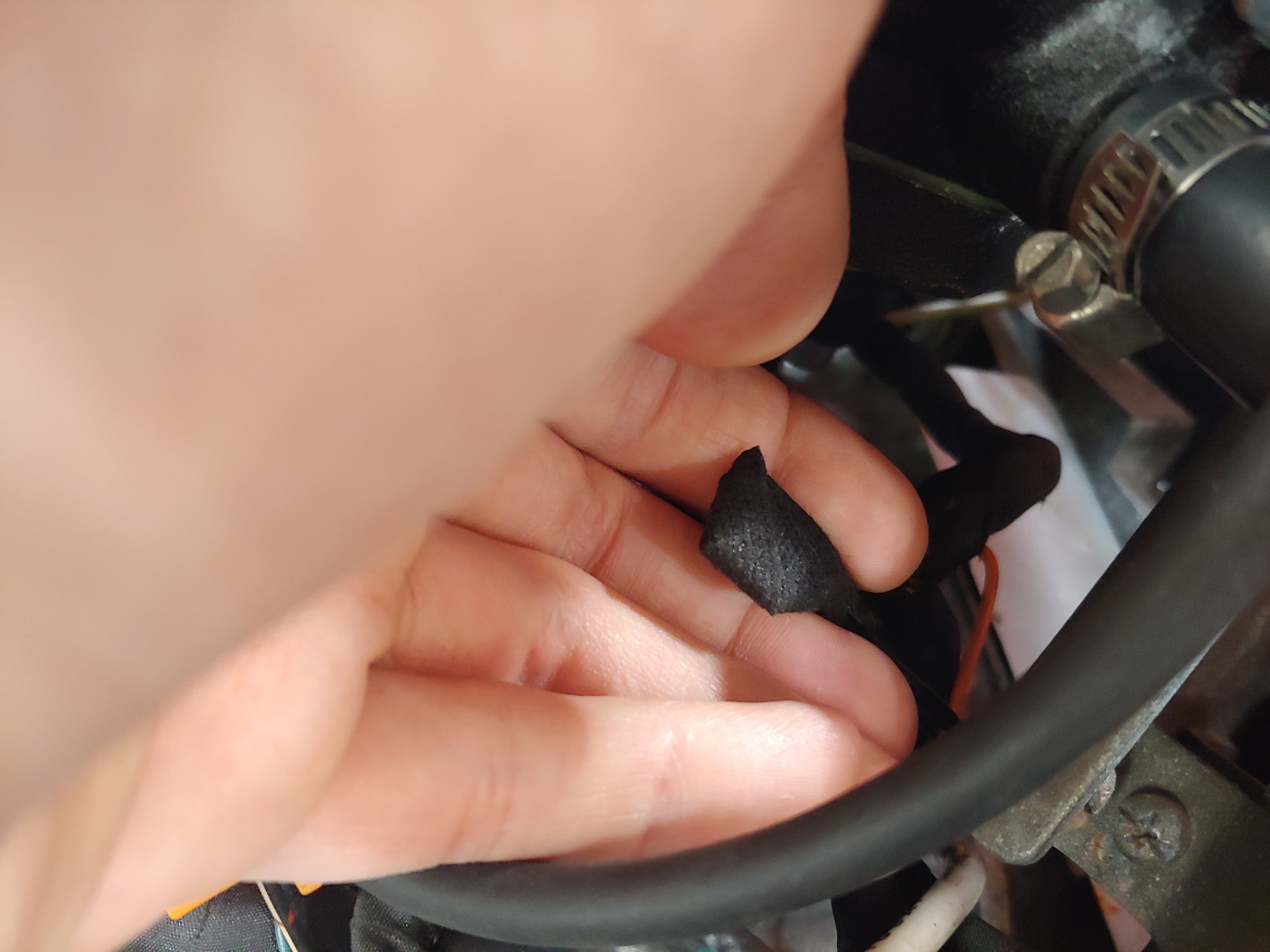
One other thing I chased down was some rattling from the rear speakers. In particular, whenever there was a heavy bass kick. I pulled off the speaker covers and tested, but still heard some vibration. Then I pulled out the speaker itself and found the culprit:
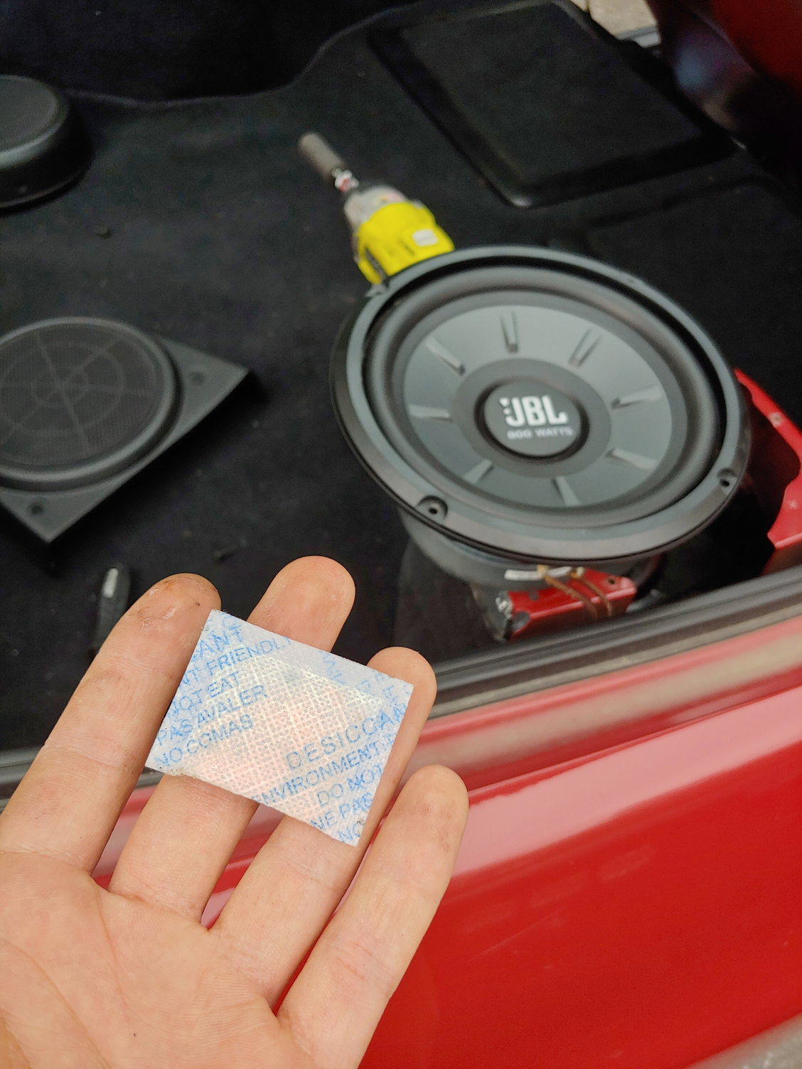
Damn. I don't know whether to be happy it was that easy, or upset that I've been hearing that rattle on and off for months and continually putting off fixing it.
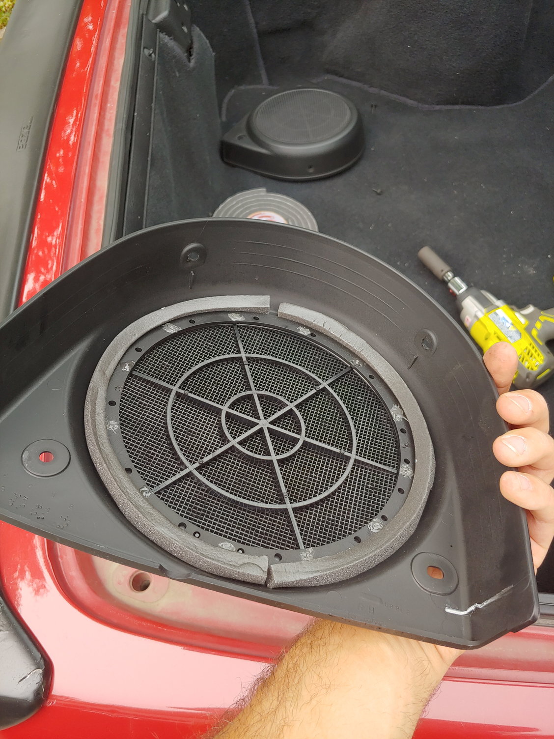
I decided to add a bit of foam to the speaker covers as a precaution. This isn't to provide a seal, just to prevent rattling. Conveniently the little track that Mazda left along the outside of the speaker opening is the perfect place to put some foam. The foam presses against the mounting flange of the speaker when installed.
In this picture you can also see some cracks forming in the corner I repaired on the defective spoiler. I got a few years out of the repair and it was my first time using fiberglass, so I'll still call it a success. It's something I'm going to fix when the car is already experiencing downtime.
And lastly, this isn't something I have actually installed yet, but it's too neat not to share it:
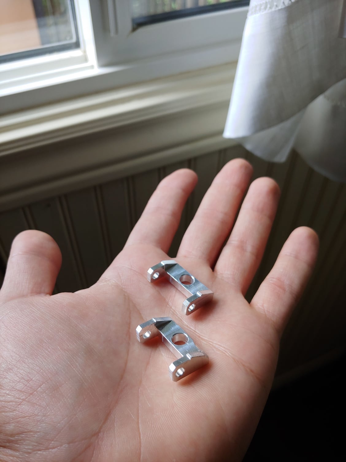
These are the sunroof deflector bracket pieces I modelled a few weeks ago. Rx7Club member Need-a-t2 was kind enough to machine me a beautiful set out of aluminum. It's pretty cool, I designed this part myself and now I'm holding it in metal. It's neat to see your own part become a reality. Thanks again need-a-t2! I'm going to inspect my current ABS parts when I remove them, and then after verifying they held up I'll make a small write-up on Rx7Club and share the STL file.
Until next time :)
With some free time this morning, I decided to investigate something that's been bugging me a bit. The steering in my car is working quite well, it just has one odd quirk: It only re-centers itself about 95% of the way. This requires manual correction on my part, and while it isn't really a safety issue, it should be addressed. I find the more you need to think about how you're driving the car, the less you enjoy the act of driving it.
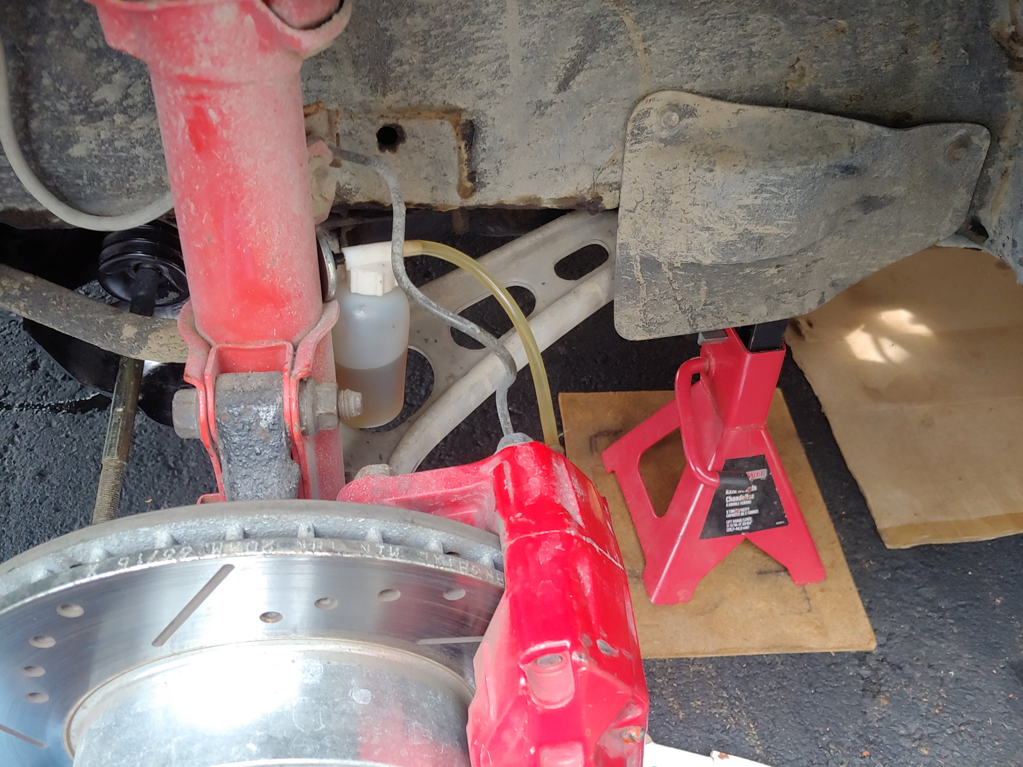
So I put the car on stands:
My research brought up the usual suspects; steering rack, inner tie rods, outer tie rods. All of these are rebuilt or new. So I checked them anyways, finding no issues. I played with the yoke adjustment on the steering rack as well, no difference. Then my research told me that the wheel bearing being loose can do this.
I've found the best procedure to check a wheel bearing (or really any other suspension component) is to just jack up the car and try to tear the wheel off with your hands. If you make any progress at all, there's a problem. In my case I found some up and down play on the passenger side. Now luckily I have less than 5000km on these wheel bearings, so it just needed tightening and not a full replacement:
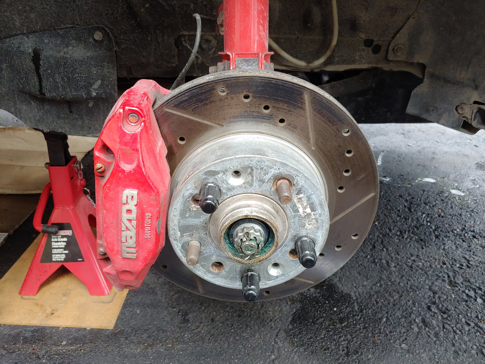
I used the factory torque spec of 14-22 ft-lbs, erring on the higher side. The wheel spun smoothly but the slack went away. I checked the driver's side and gave it the same torque spec. But then I noticed on the driver's side there was no up and down play, but some side-to-side play. I found a different culprit:
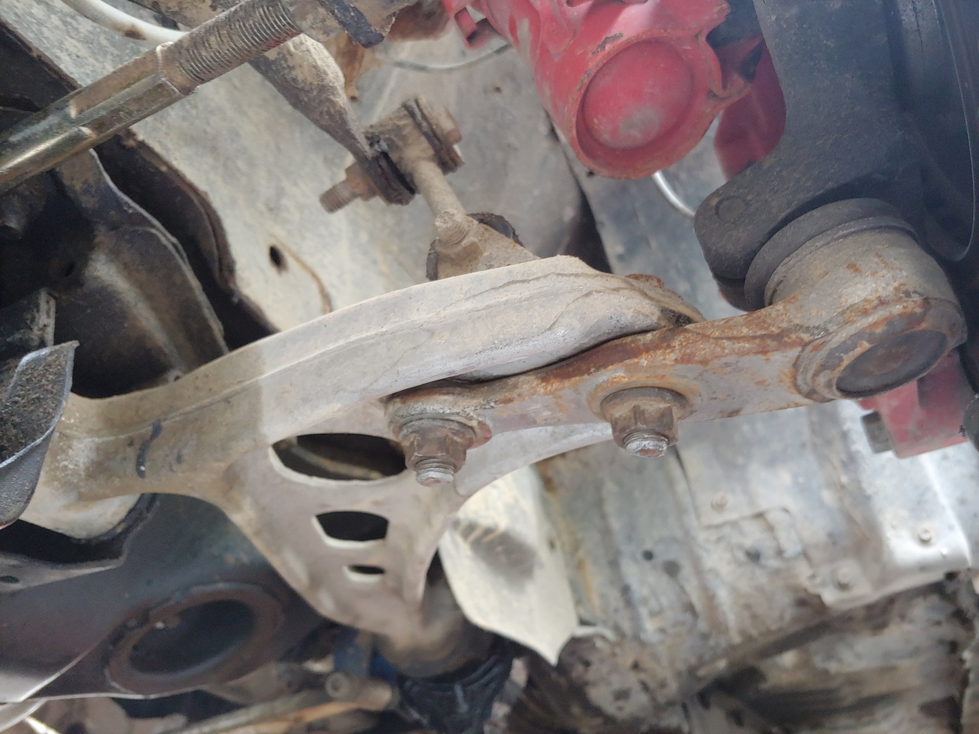
None of the crusty looking components, everything is new, it's mostly mud from the end of my driveway. And not the ball-joint itself either. The mounting nuts. Both mounting nuts were loose. I removed them by hand. And I can say with 100% certainty that these were tight before I got my alignment, because I specifically went and re-torqued all the suspension components to spec beforehand. I don't normally go blaming the shop for a small mistake, but that's pretty serious. I removed the nuts and cleaned the area before adding anti-seize and torquing them down... or torquing them up, whatever the correct term is. Then I bled the brakes in the front, because why not:
Now, I spent some time second guessing whether I had left the ball-joint nuts loose or the shop had done it. The rear of the car was already lifted though since I wanted to check on a transmission fluid leak, so I checked the rear suspension too. Guess what else was loose?
Yup, the upper lock-nut on the camber link. Now it was only loose on the upper nut, so it couldn't back out all the way or anything, but still. Come on. I also pay more than market rate for my alignments since I trust that my usual shop does good work, and they have in the past. I've seen them install my lug nuts properly with a torque wrench rather than banging them on with a rattle-gun, which is what made me comfortable taking it to them. So I'm willing to accept this is a one time error, but I'll still be keeping one eye open for another shop. Alignments are the only thing I outsource since I don't have the equipment to do it as accurately as a shop, and still it's wrong.
The transmission fluid leak turned out to be coming from the plate on the side of the shifter housing, which makes it a transmission-out job. The transmission will already be coming out when I swap the TII driveline. So I'm just going to keep throwing cardboard under the car for now. And if you've noticed some of the rust on the suspension in these photos, so have I. I stripped and repainted everything a few years ago and they were looking great until last fall. Shows you what one winter does to a car. Nothing serious, and nothing on the body of the car, but still.
After fixing the issues the steering wheel still doesn't return to center perfectly, but it's definitely better overall. It feels much sharper and has less tendency to tramline on poor roads. It's a small but noticeable difference. I think the steering wheel could be over-tightened too, since I can remove the nut but can't pull the wheel off the column. I don't know if an over-tightened wheel could cause this issue, but it's the only thing I haven't tried, and since there were issues with the rest of the alignment I no longer trust that it was torqued to spec and not rammed on there. I used to be able to pull the wheel from the column by hand, albeit with a lot of force. Further investigation will be required.
Overall, improvements have been made. Until next time :)
I spent a good half hour last night trying to remove the steering wheel, with no success. I used a two-jaw puller to try and pull the wheel off, but the wheel started to bend instead of pulling from the column. Not just flex, but actually bend. So I stopped and decided to leave it alone until I have a three-jaw puller. This morning though, that became unimportant:
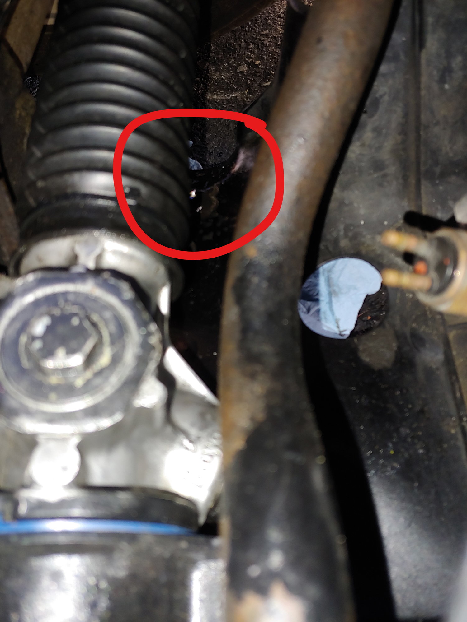
Yup, grease and ATF pouring from the driver's side steering rack boot. At a certain point, it's starting to feel personal!
Having become very practiced at removing the steering rack, I find the best way to drain the fluid is to loosen the clamps on the return hose and remove it from the pump side, and cap the pump inlet. Then direct the hose into a container and spin the pump with an electric ratchet:
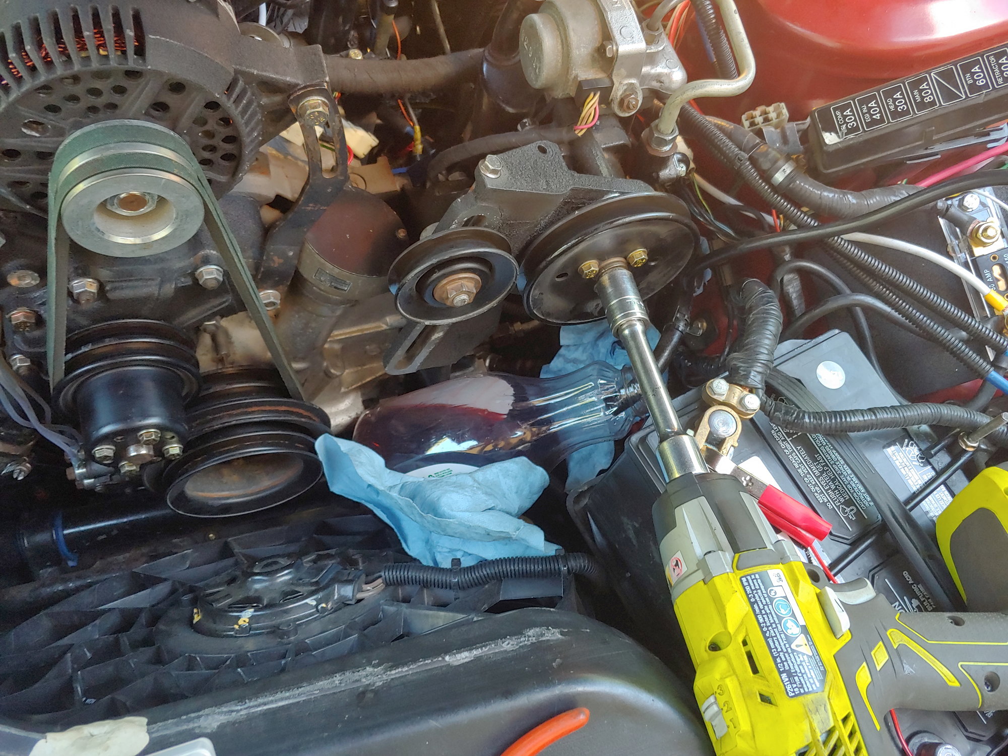
Makes quick work of the draining process. Then flip the hose to the pump side and let anything else drain. That will get the bulk of the fluid out.
Anyways, a rebuilt rack with a 3 year warranty is on order. I was hoping to buy more parts for the turbo swap, but at this point I am not going to bother rebuilding this rack again. I'm certain I got it right last time and it still failed, so maybe the minor scratches on the rack itself are too much and it is no longer a good core. And the rebuilt rack was only a bit more expensive than having my rack rebuilt professionally (which again, wouldn't help if the core is bad). The rack won't arrive until at least next week, but this is exam week anyways so my time is limited.
It's a bit disappointing, but overall I'm not that upset. I may try de-powering the old rack properly, since it is no longer suitable as a powered rack. Plus I'm an expert at rebuilding it due to the multiple efforts. One thing is for sure, I'm going to ask the next shop I take it to for alignment not to over-torque the column nut.
Until next time :)
The rebuilt steering rack arrived today. Out of the box it seems okay-ish:
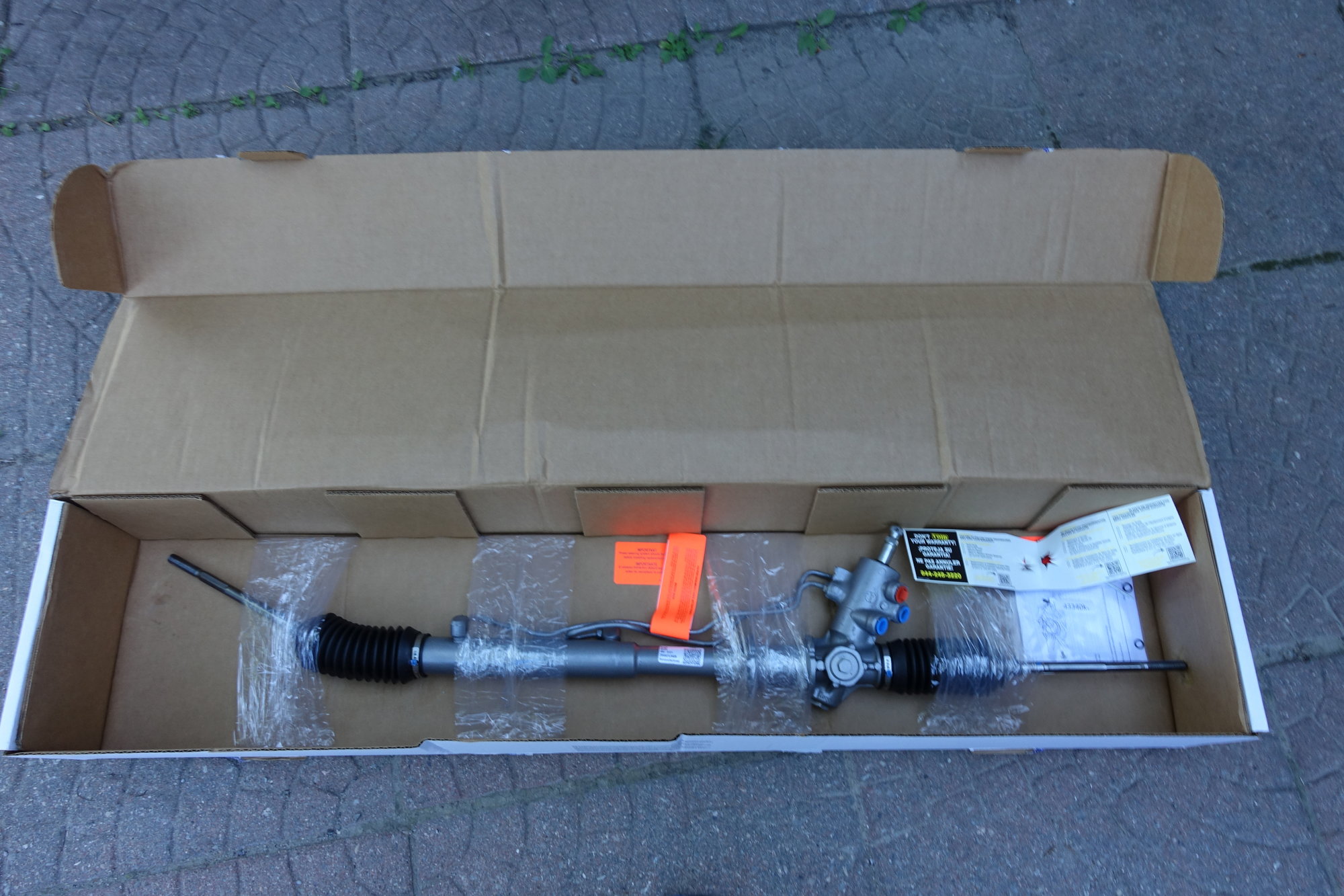
There are exactly three things that concern me:
- First, the line at the back that runs from the pinion housing to the far side has a slightly unusual bend. I'm guessing it was dinged on removal from the previous car, and then no-one at the rebuilder noticed.
- Second, the rack came with a little notice that "there will be no returns accepted for a rack with damaged threads, and all threads are inspected thoroughly before the rack leaves the factory". Which wouldn't be a problem, except the threads on the return line port were clearly a bit funky out of the box.
- Third, they did the lazy rebuilder thing and just spray painted the whole assembly silver (painting right over grease while they did so) instead of blasting it or painting the parts separately. This is purely cosmetic, but still.
Taking the old rack out was fairly straightforward, since I've done it so many times. Undertray, battery, tray, e-fan, and sway bar come out. Then it's a few fasteners and you're ready to pull the rack:
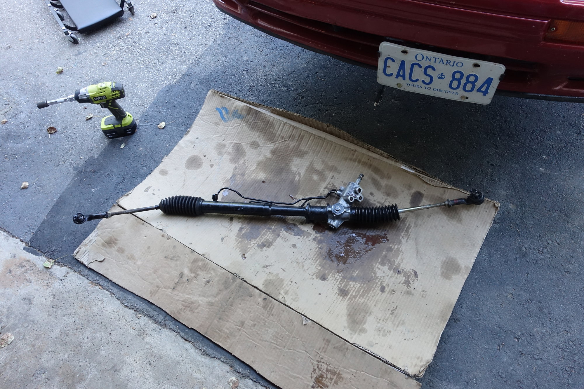
I tried counting the threads for each tie-rod end, but the inner tie-rods had a different amount of thread. So instead I measured the width of the old rack from the outer edge of one tie-rod stud to the other. Then without moving the tie-rod ball joint, I installed them on the new rack and adjusted to maintain length. Then I installed it in the car, with my dad helping to hold the steering wheel straight (since I can't remove the wheel to recenter it):
If you look closely, you can see the problem I mentioned with the hardline. Out of the box, the line collided with both the mount bracket and the bolt. I adjusted it a tiny bit by hand and it now clears, so it should be alright:
It's a bit frustrating that a rebuilt part comes out-of-the-box with this lack of attention to detail. Especially since they offer a limited warranty but then immediately wash their hands of it with 15 disclaimers in the box. It wasn't cheap either.
Having everything installed, I added fluid and carefully bled the system. Then I checked for leaks and took the car for a drive.
Overall, it's hard to say if the rebuilt rack has fixed anything (other than the leaks, of course). The steering now returns to center even less than before. Part of the issue is probably that the steering wheel is no longer centered. This means the angle sensor for the computer is also not centered, so that probably contributes to the issue. Even though it tracks straight I am still going to get an alignment (leaving the new shop a note politely asking not to over-torque the steering column nut) to eliminate all possibilities. I don't actually expect the alignment to make as much of a difference as the loosening of the steering wheel...
Today was my last exam, and after it was complete I visited some family in Toronto. I also picked up something really cool. A member of the GRM forum contacted me, and generously offered me a Turbo II driver's seat that he had reupholstered and mounted as an office chair. When I asked what he wanted for it, he told me it was free to a good home!
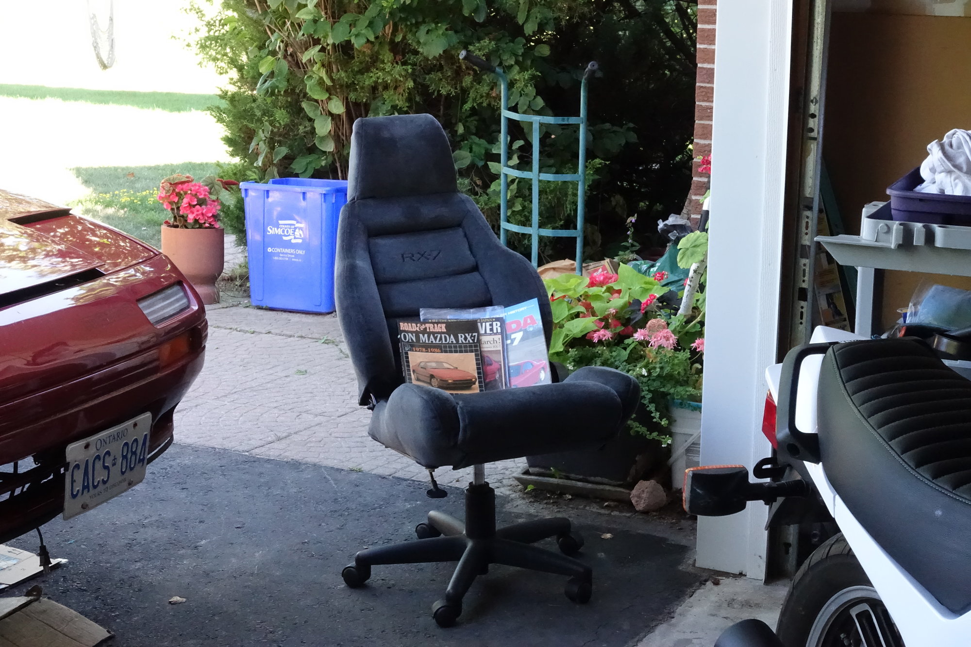
The dark spot in the photo is from the nap on the fabric; if you brush all the fabric the same direction it looks consistent. He reupholstered it himself in this nice dark fabric, and it even has an embroidered logo:
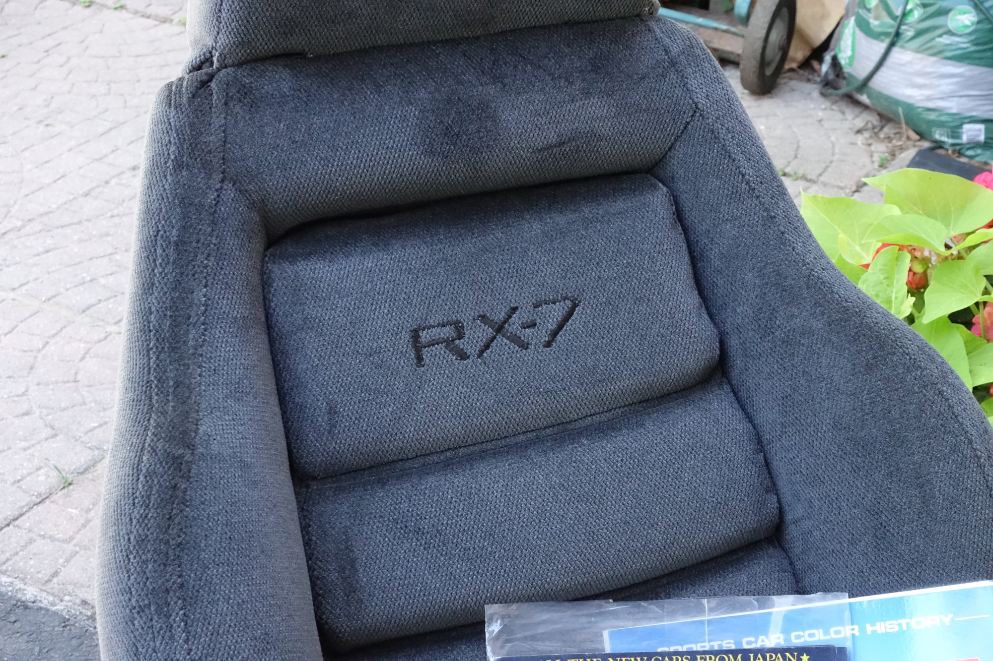
Really impressive work.
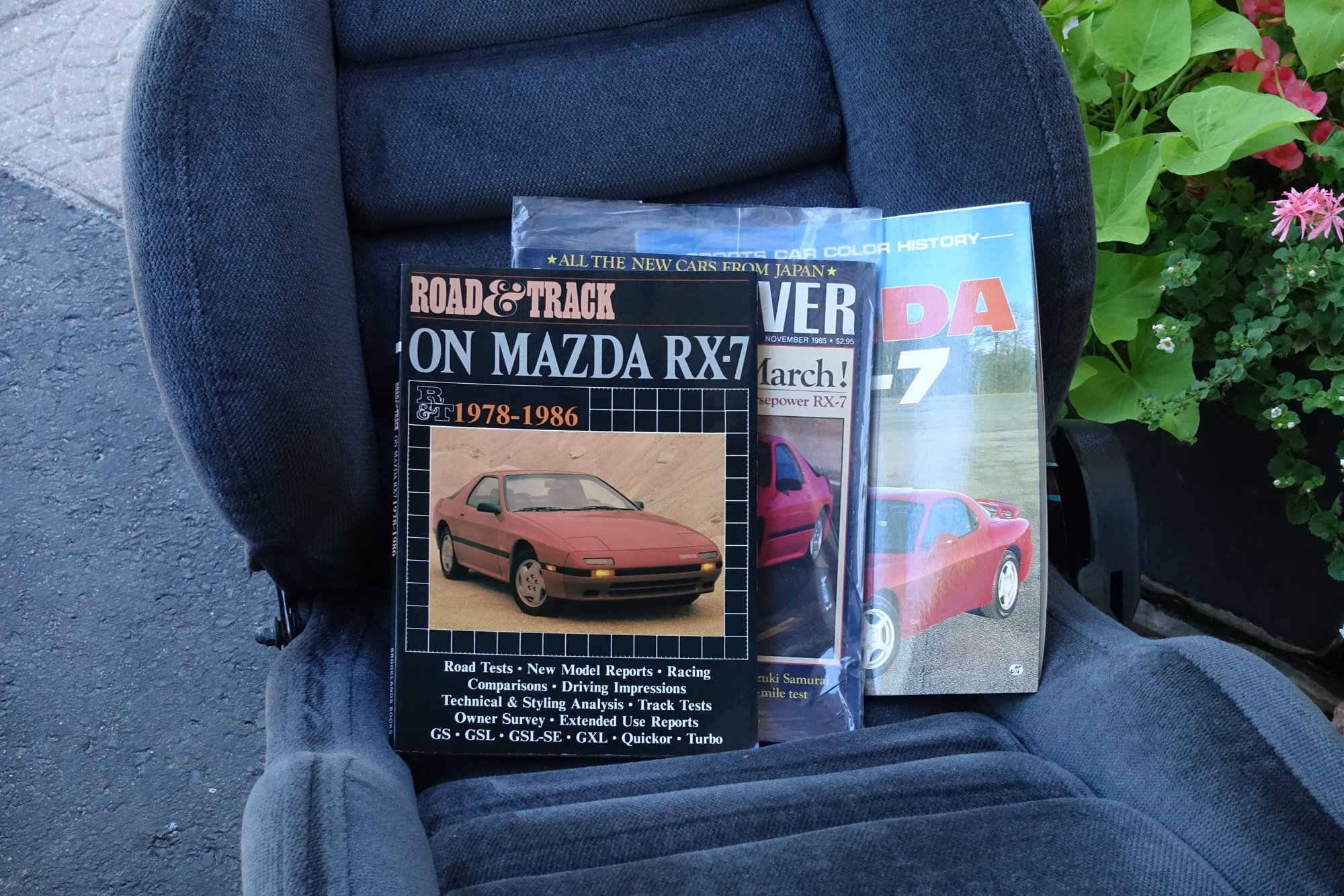
He also surprised me with some cool Rx-7 related reading material; Road and Track - On Mazda Rx-7, November 1985 Car and Driver, and Sports Car Colour History - Mazda Rx-7. Really neat stuff.
While I am tempted to mount the seat in the car (I slide all around my leather GXL seats when turning), the leg is falling off my current desk chair. So for now at least it will remain an office chair. Thanks again Curtis!
Hopefully I can get an alignment sometime next week, work schedule permitting. Until next time :)
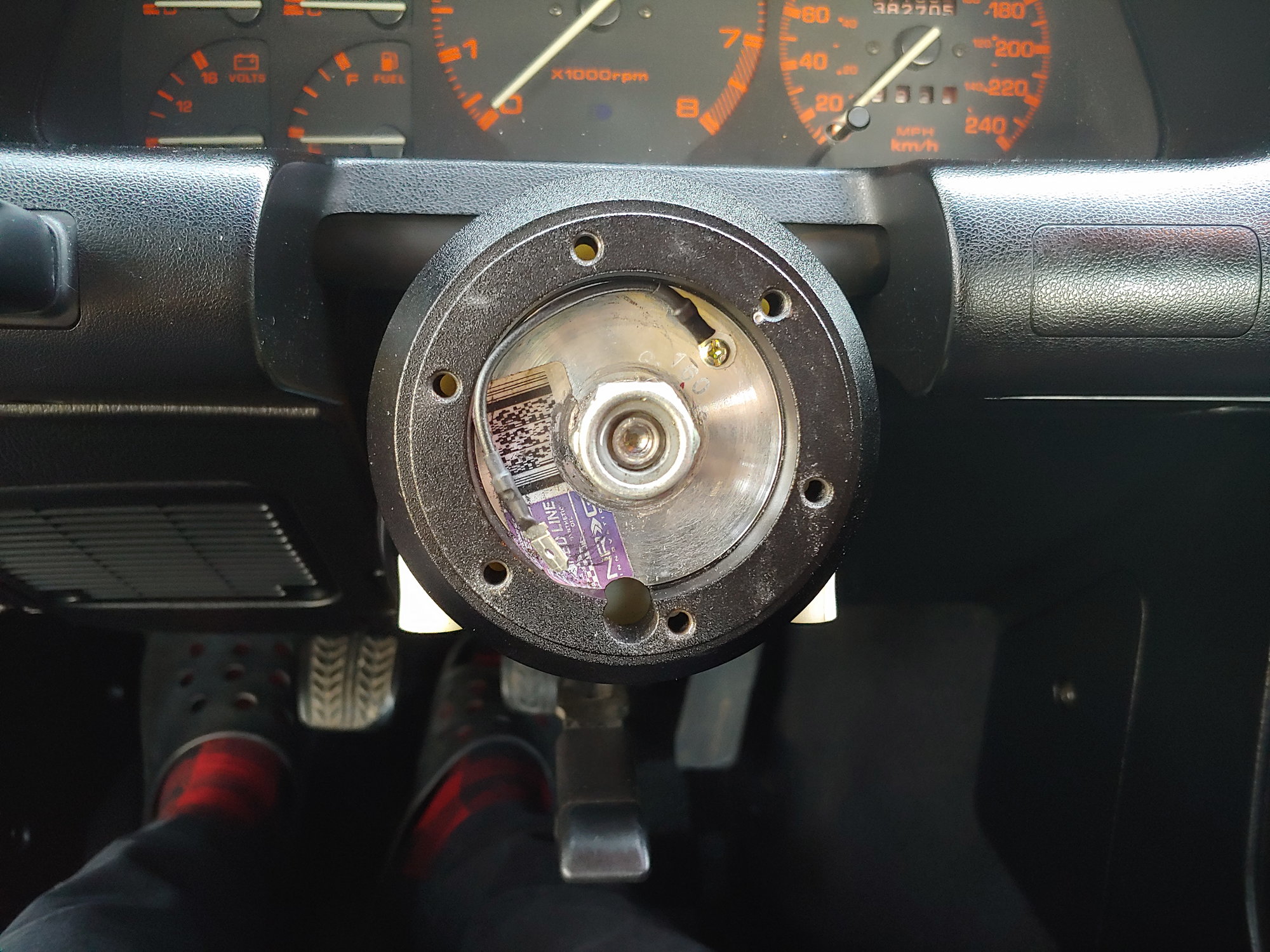
I mentioned before that the puller started to bend my steering wheel. So I had to dig in a bit deeper before proceeding. First I removed the column plastics, which both came free with a loud pop:
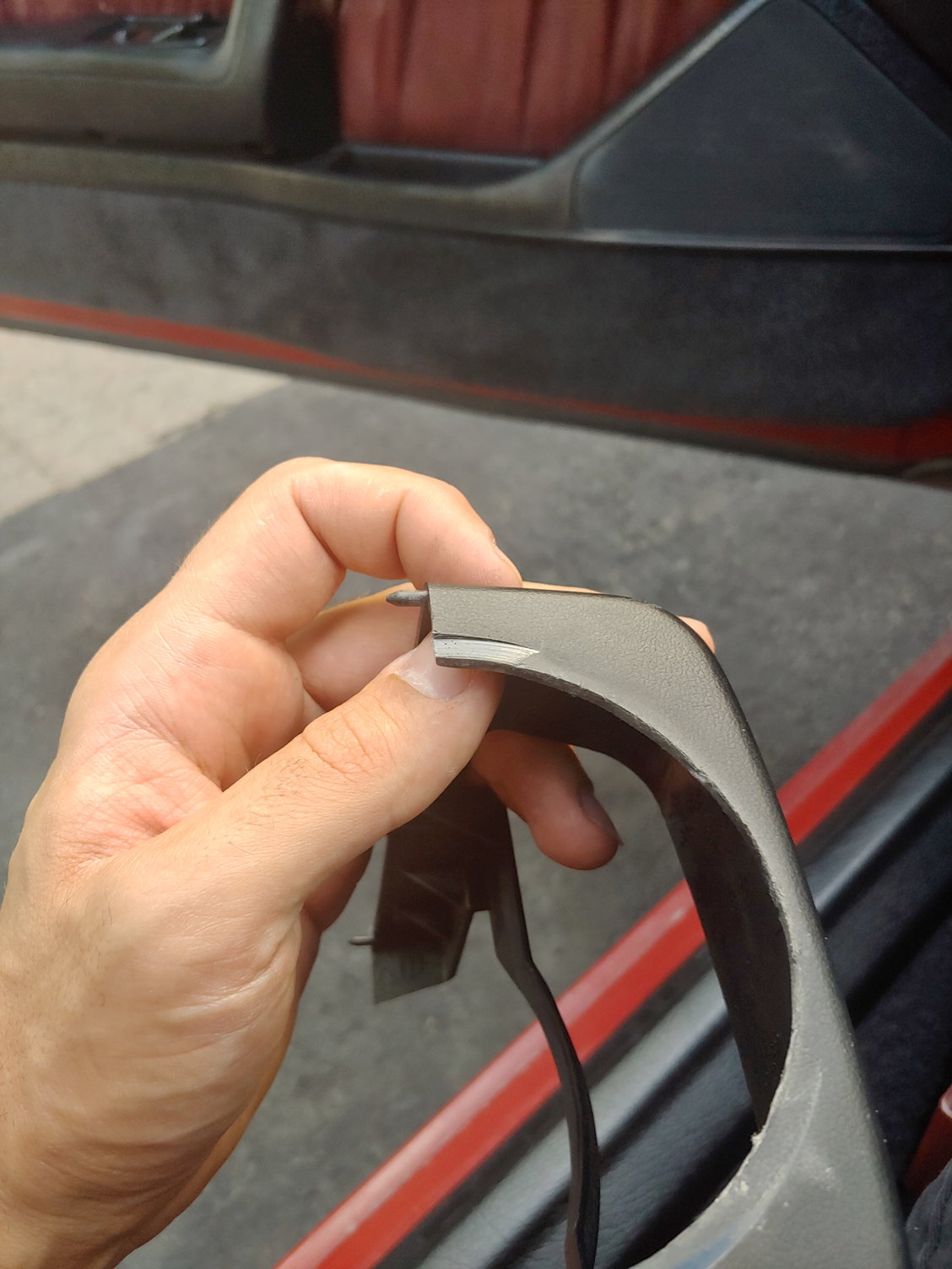
I could feel a bit of friction between the hub and the plastics, but didn't realize just how much the hub had ground out. Keep in mind that I actually cut this fresh OEM piece for the hub when I first got it and there was zero collision, so this is purely from the nut being over-tightened. Here's some of the ABS dust I found floating around inside:
And as if that wasn't sign enough, the nut was tightened so hard that the bottom of the nut started to mushroom out. Also, the split lock washer used to be a lot more "split"; it's been flattened out some:
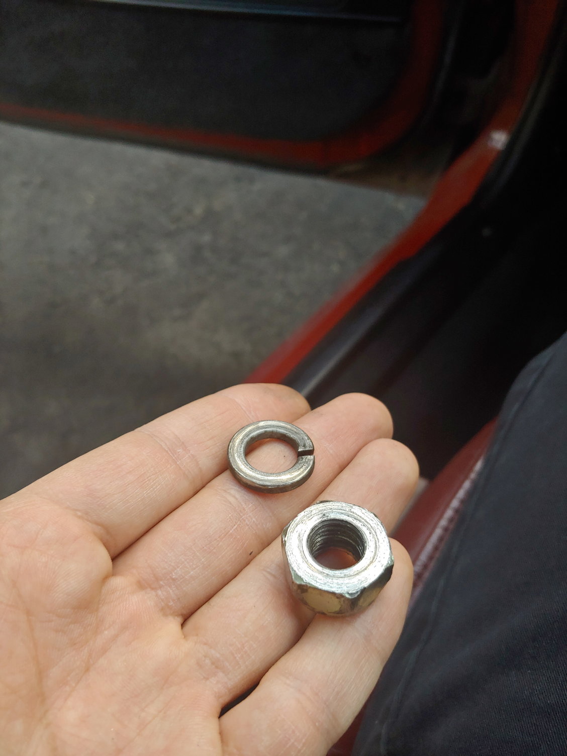
And I pulled a nice pile of shavings from the threads:

Then I had the hub exposed, which let me use the puller to grab the outside circumference:
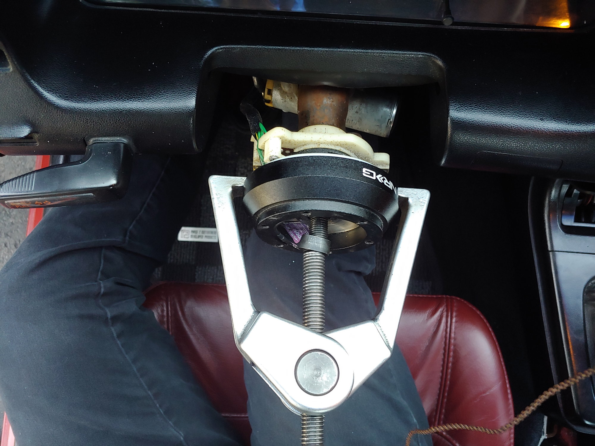
(The little cup on the puller is bent, but it still sits fine on the flat of the column. It was adjusted after this photo was taken).
And since the hub was much sturdier than the wheel, I could actually pull it free. Not without a lot of effort though. I cranked it all the way down by hand, then with a breaker bar, and then I used a Ryobi electric impact wrench on the highest setting. After about 30 seconds of impact, it made a very loud "bang" noise and moved about 1/8". Then I tried to remove it, but it was still stuck on there. So I impacted it again for 15-20 seconds, and it made another loud bang, and moved another 1/8". And I just kept at it until eventually it came free.
It was on there so far that it was hitting the plastic assembly that holds the steering angle sensor. Which is way too far. If that isn't clear enough to visualize, here's another way to look at it:
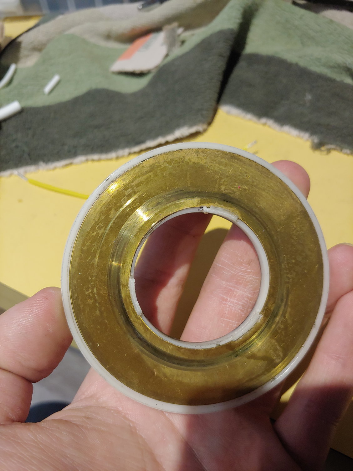
That round mark is from the spring-loaded plunger for the horn contact. It gets a dollop of grease, and spring pressure holds it against this slipring and makes contact for the horn. The scratching isn't unusual since there is metal-metal contact, but what is unusual is that the entire ring was creased inward along that line. Not in the extreme, but enough to be visible. This means that it was on there so far that the spring compressed entirely and the horn contact was slowly rolling a bead into this brass ring. Wild.
With that apart, I replaced the horn wire (broken on removing the hub), then put it back together. And man, what a difference.
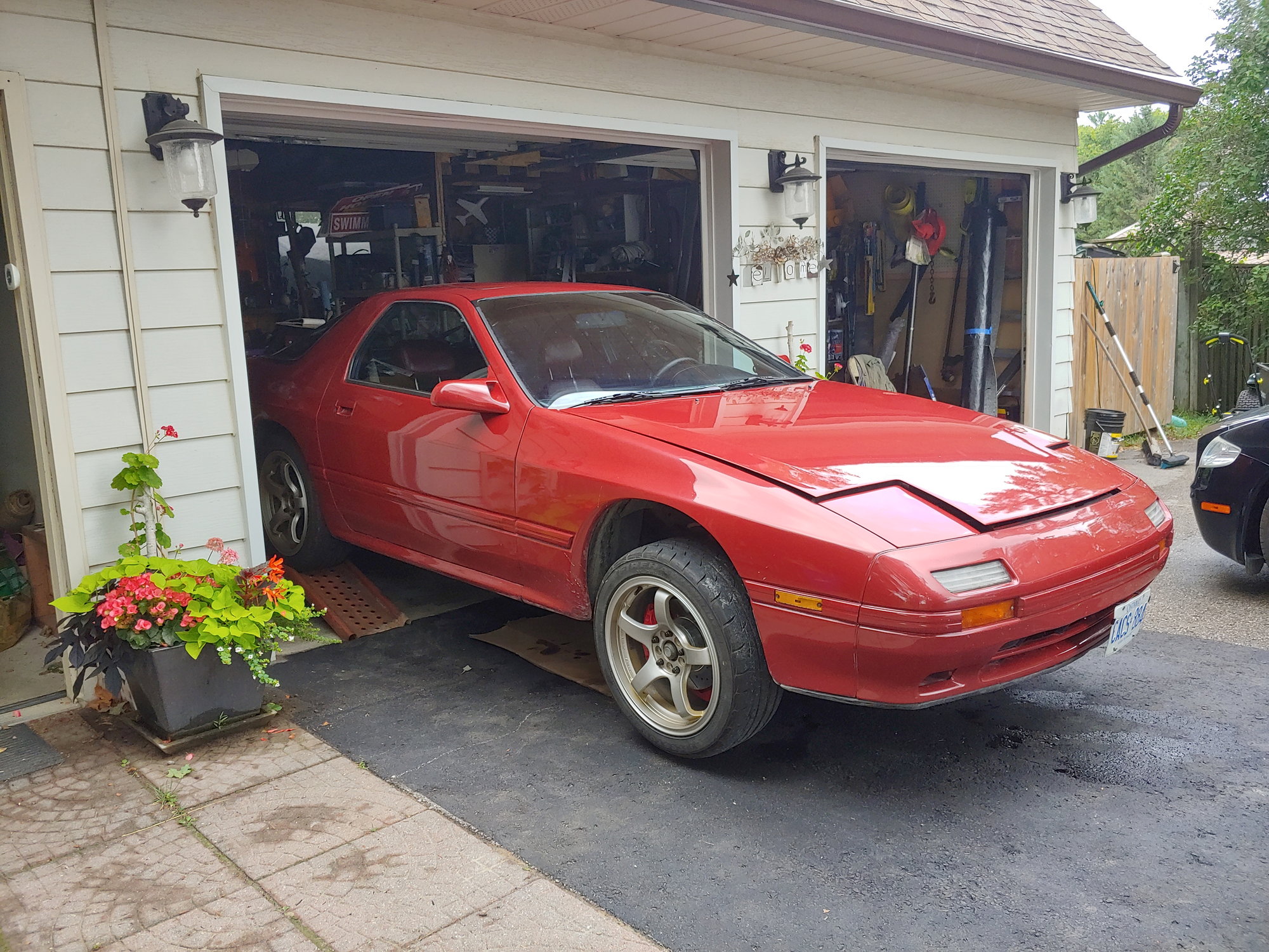
I don't have a great frame of reference since my Celica feels entirely different, but the steering now feels more natural. It returns almost all the way on it's own (not 100% though), but I'm having a hard time telling what is normal anymore. I have changed so much on this car in the past few years that I only vaguely remember how the steering felt when I got it. I took a test drive and stopped to take a few photos:

The speed-sensing function of the computer is quite nice. You can feel it vary the assist as you accelerate, and then the angle-sensing function lets you make small inputs easily and then gives firm road feel for larger inputs. Really neat. Plus, since the wheel is straightened out and the car isn't wandering at speed (due to measuring the old rack before installation), the alignment is no longer urgent.
So for now at least, I'm calling the steering fixed. I might still get that alignment just to eliminate every possibility regarding the wheel centering, but the required correction is very minimal so I'm not too worried.
Until next time :)
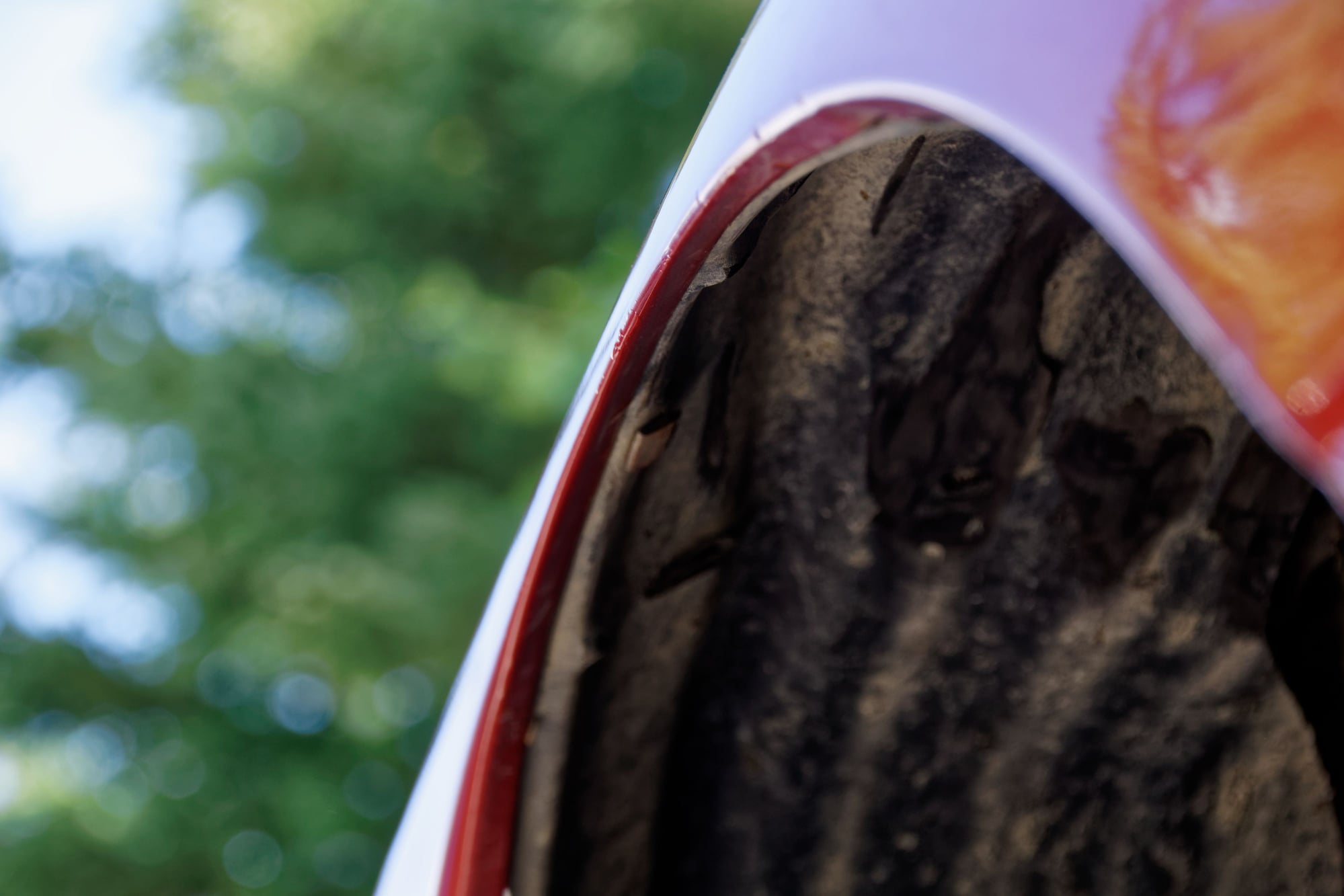
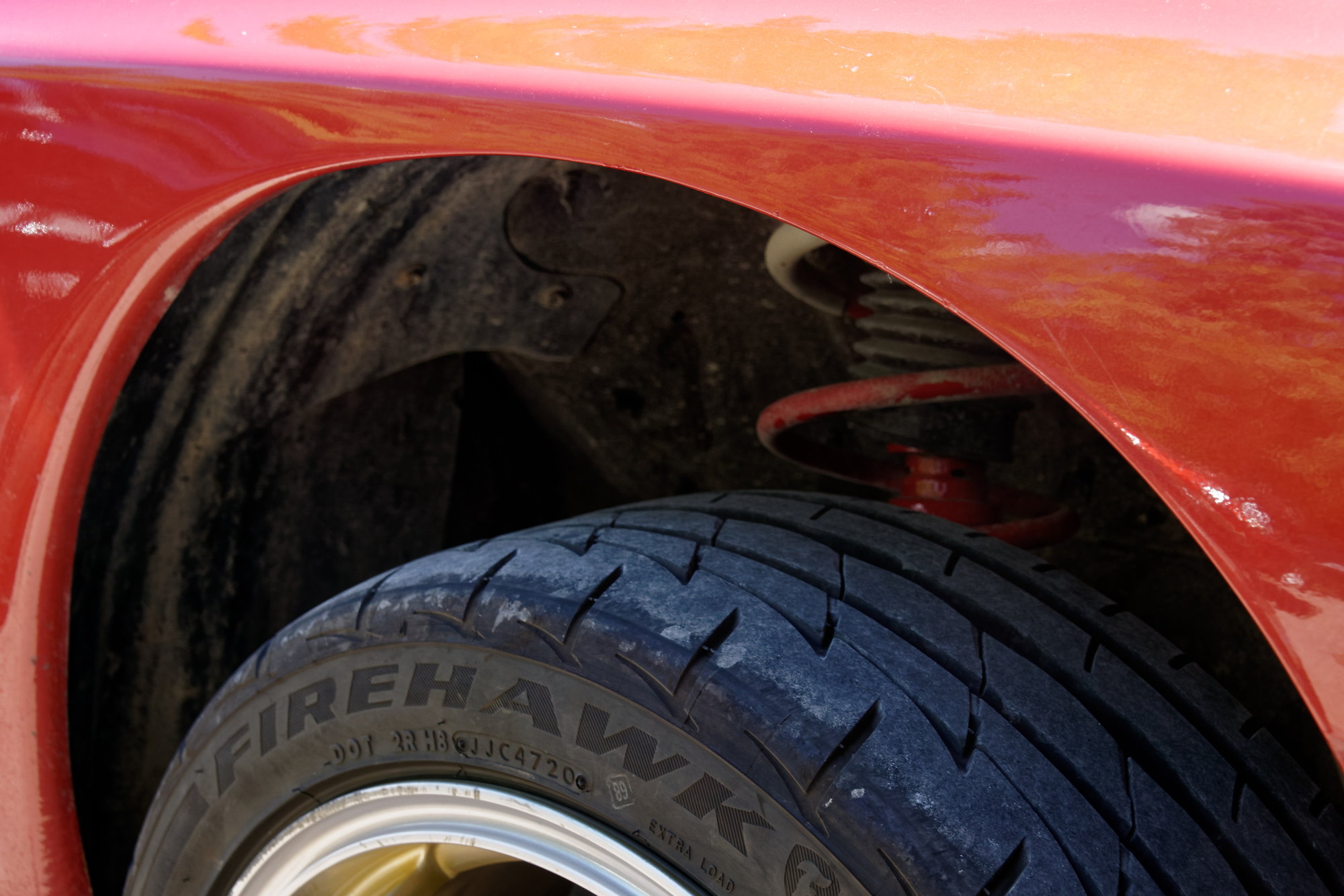
One thing I had hoped to avoid when I bolted up wider wheels was modifying the body. With stock style springs in the front though, you are limited to around 8" due to the size of the coil, and you need to get the perfect offset to achieve that. Now since I am running 7.5" wheels with a 225 tire I thought I could get away with it:
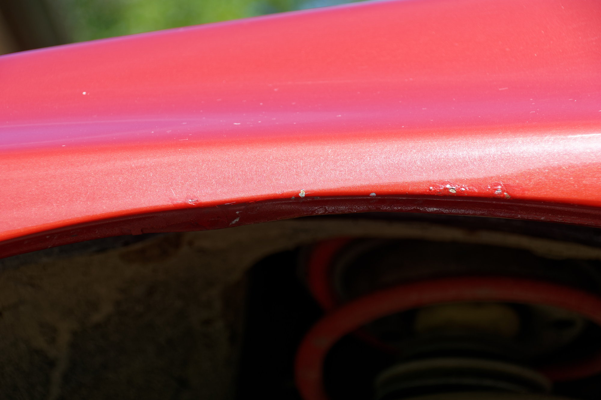
The potholes at the end of my driveway had other ideas though. Every time I leave the driveway I get some rub on the tire, and it pulls down this little spot on the fender. So it was time to do some rolling. I bought Amazon's finest fender rolling tool:
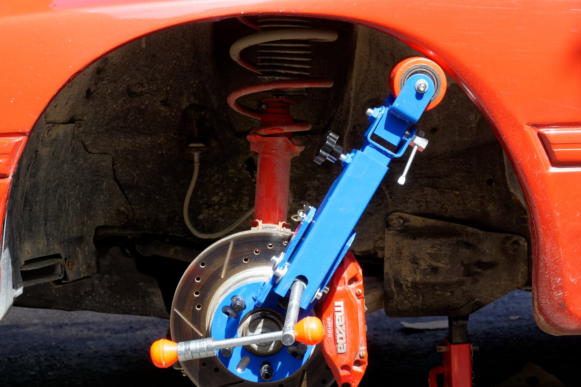
It's exactly like all the reviews say; If you're okay with the fact that it's manufactured to the nearest 1/4" and don't mind having to loctite every fastener on it before use, it's perfectly fine for the price. If I intended to use it more often I would have sprung for the Eastwood version, but this one is fine for my purposes. And yes, I did realize the little rings on the handle are for the conical lug nuts before I actually started rolling.
I used the heat gun to get everything softened up, but since my paint already has some chips and cracks in this area, I was really just looking to minimize any further damage. Normally you would start with the tool inside the wheel well and angled to push the lip up, but I started by just pushing the lip of the well back into it's original shape. Then I angled the tool and slowly starting working the lip up and folding it over:
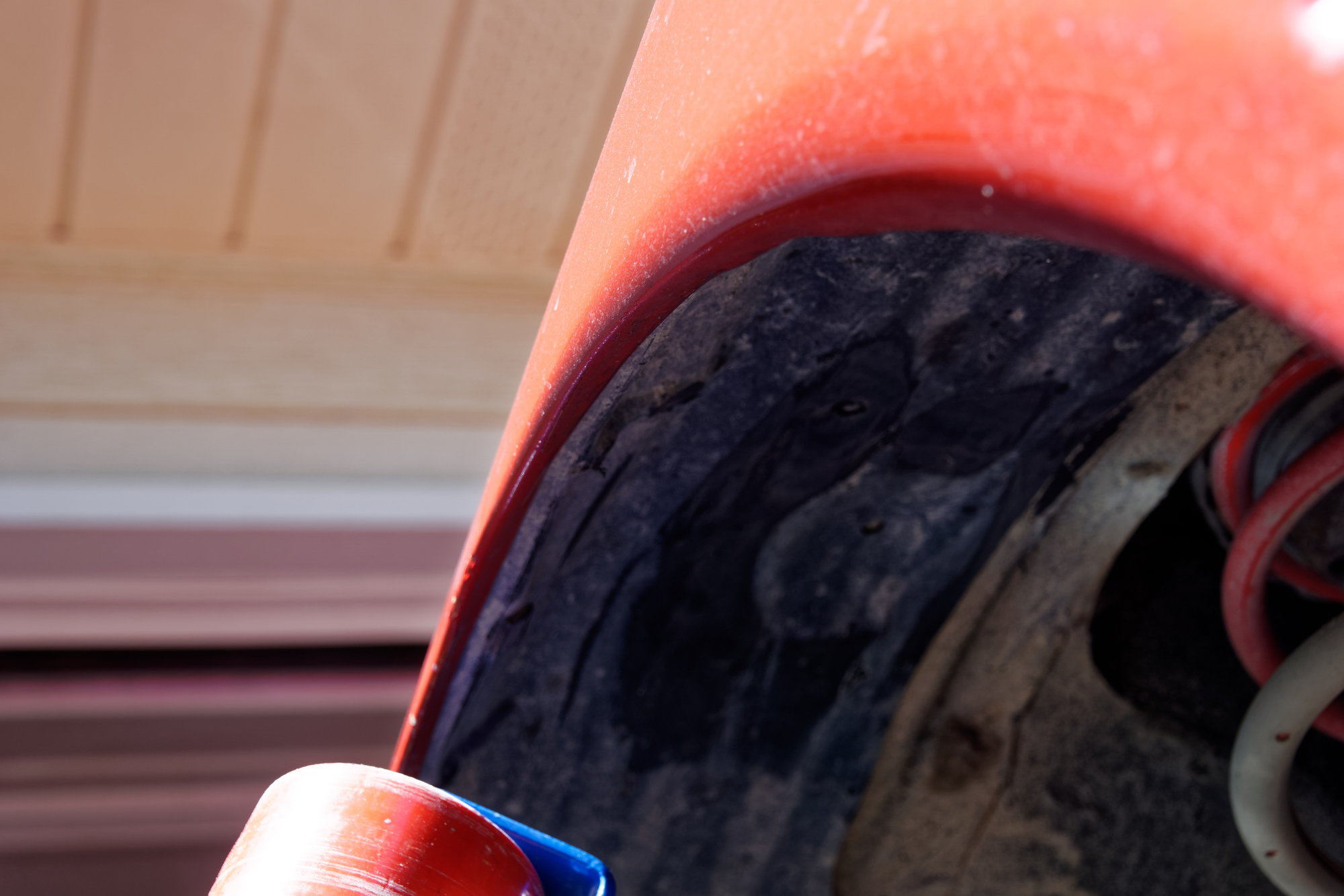
It took about 15 minutes start to end on the driver's side. Then I moved to the passenger side. The hardest part was that the nut on the end of the tilt adjustment for the tool would back out when I turned the handle to push the roller against the lip. So I would have to turn the handle, then spend a couple minutes tightening the nut with a wrench to actually push the roller where I wanted it to go. A bit of a pain, but again, that's what I get for buying the cheap tool. After working away at it for awhile:
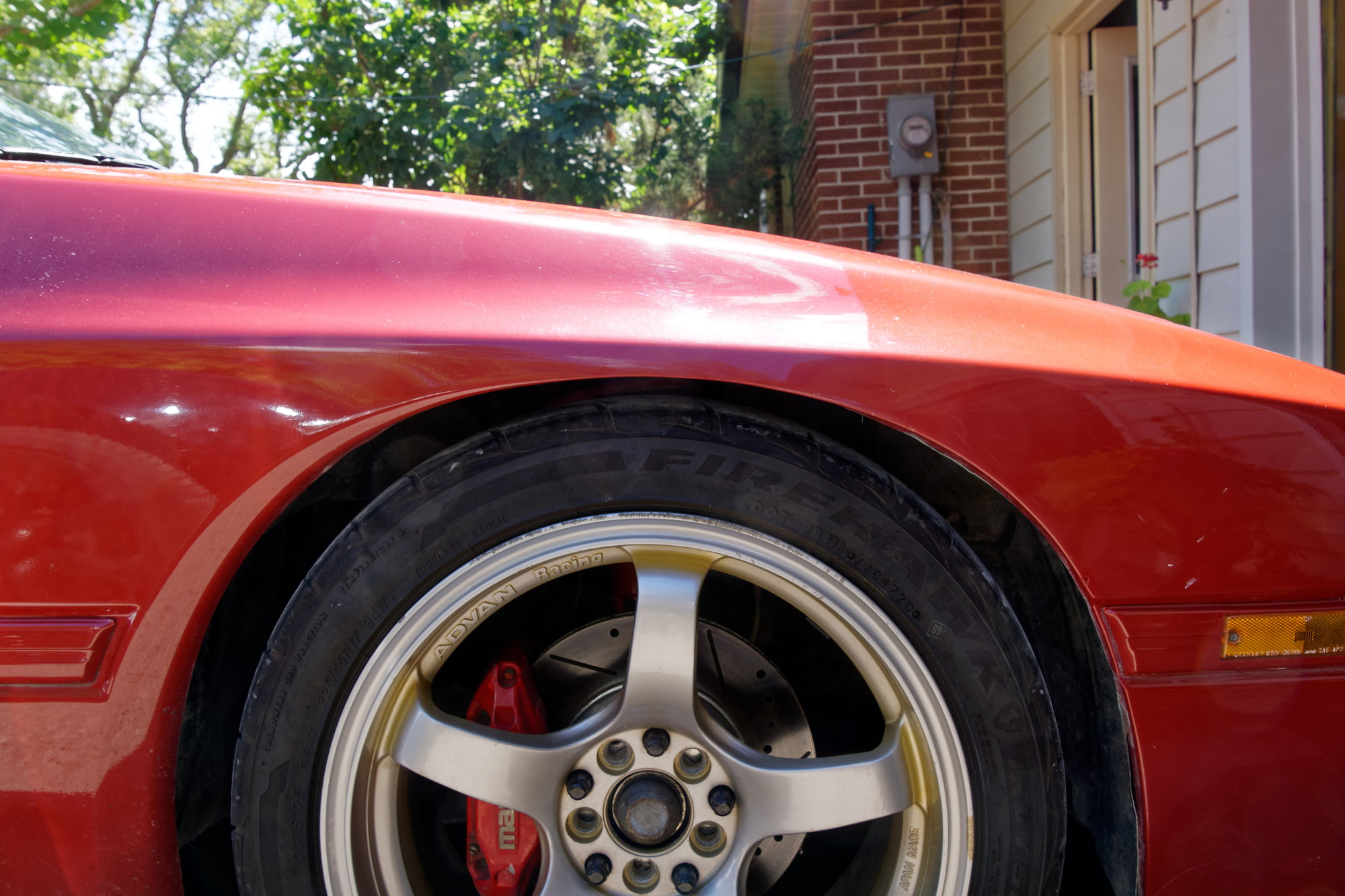
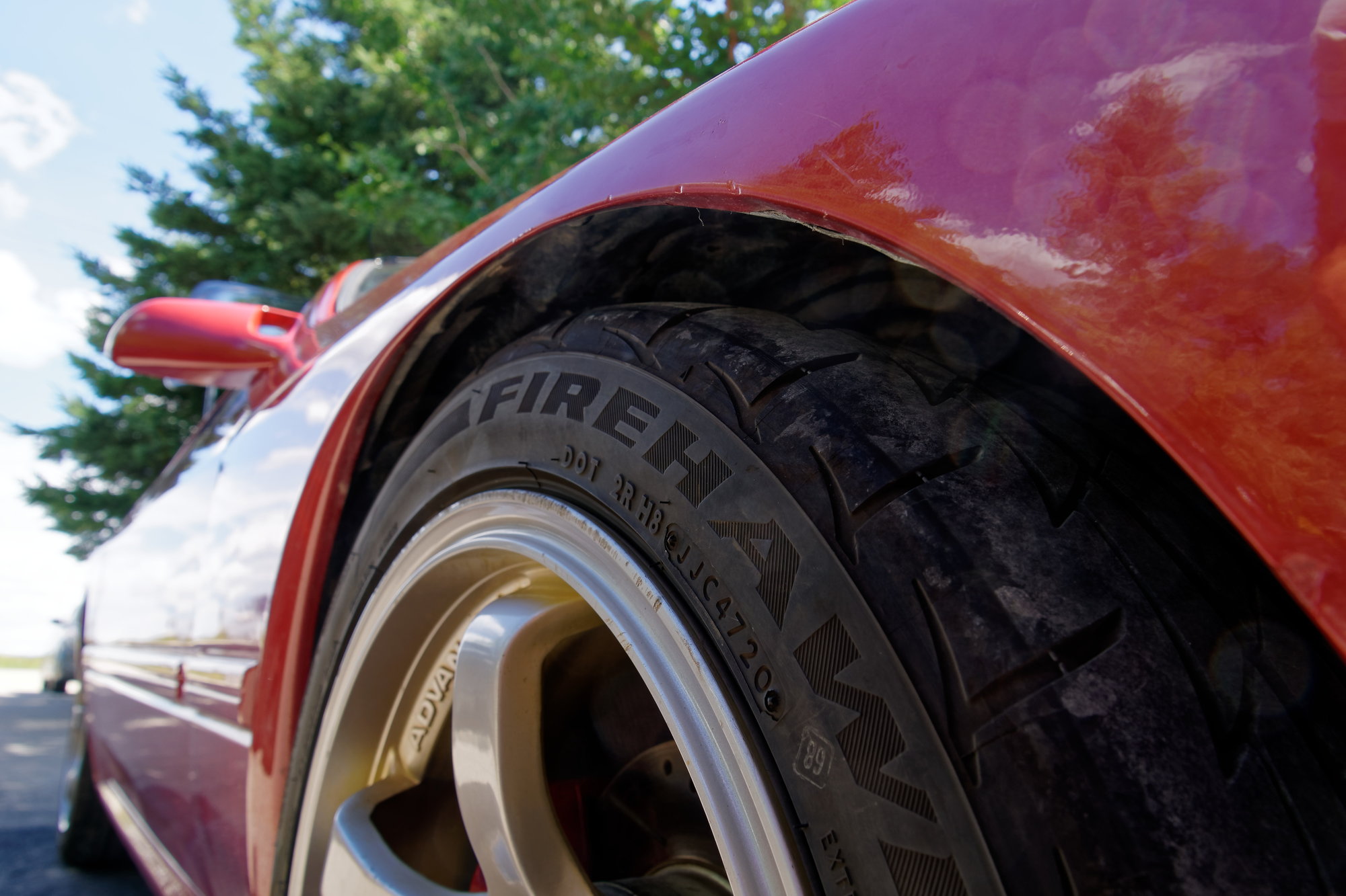
No paint damage, which is nice considering how old my paint is. I didn't take it to the extreme. I just wanted to roll the lip up enough to prevent any more rubbing, not actually change how it looks. The new profile should be enough for now, but I'll be checking periodically to make sure I went far enough.
I also fixed the rolling tool with some grease in some areas and loctite in others. It now works very well, only to sit on my shelf indefinitely. Until next time :)
I thought I was done for the day earlier, but I squeezed in one more improvement on my Rx7. I mentioned before that I was sometimes seeing the coolant temps become higher than expected while cruising. At this point they certainly aren't too high at about 194F when cruising on a fairly hot day, but it's higher than I think it should be.
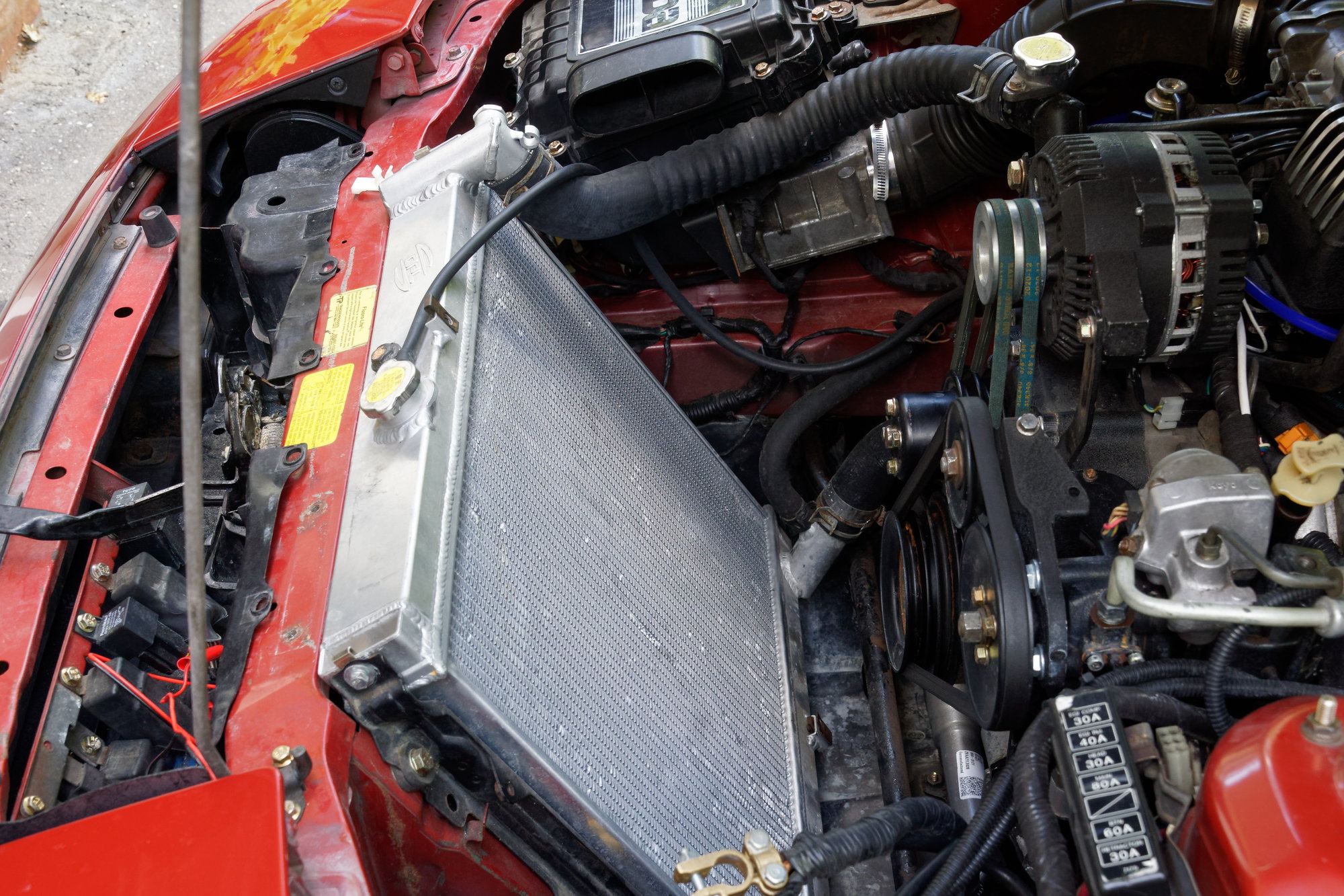
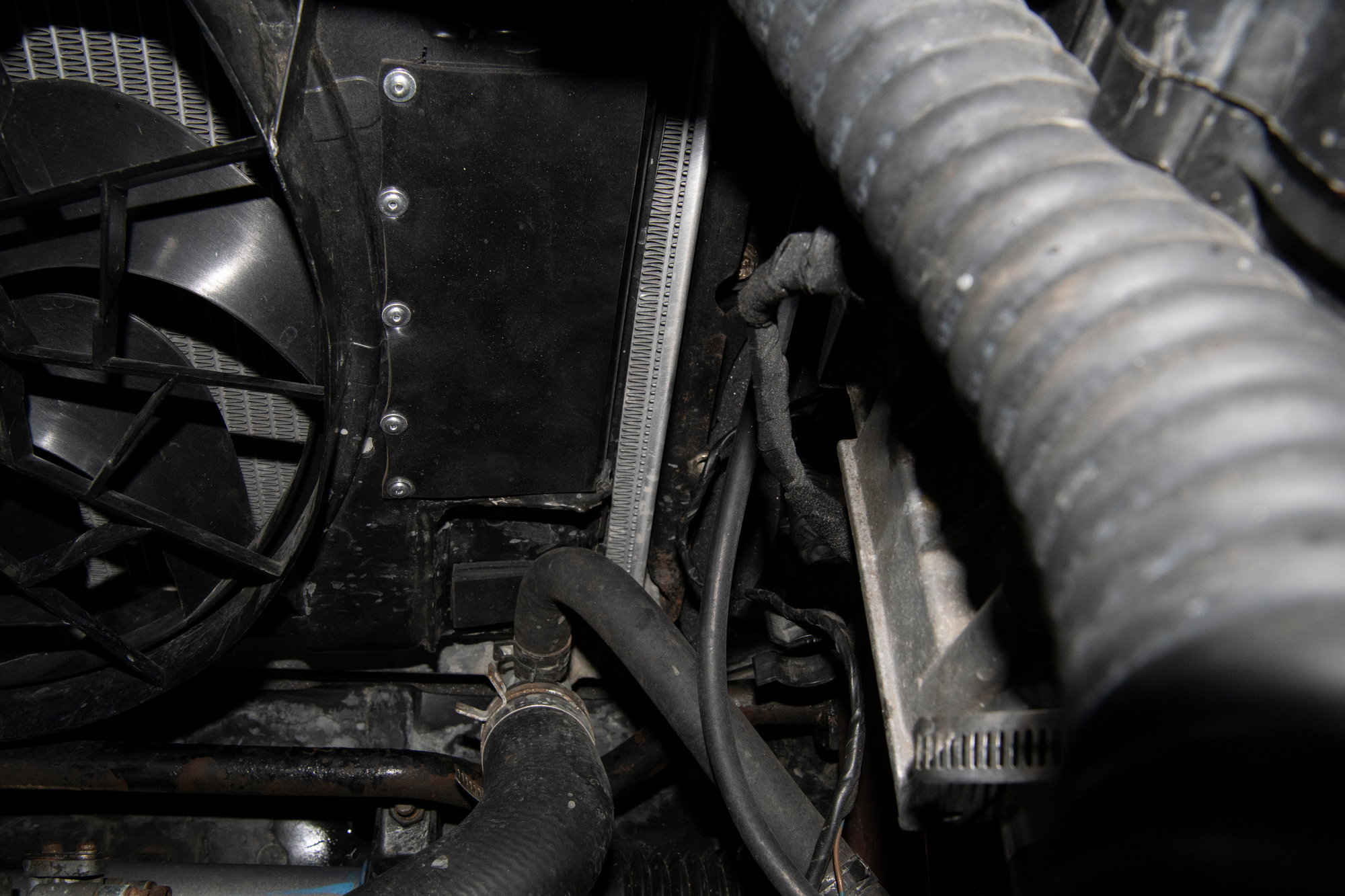
One idea I had for the cause was that the fan shroud is too restrictive. I'm currently using a Ford Taurus electric fan. It's a perfect fit for the rad and it cools the car very quickly when active. However, the shroud itself might be a restriction at higher speed when air is trying to squeeze through the radiator. Namely, this big flat area:
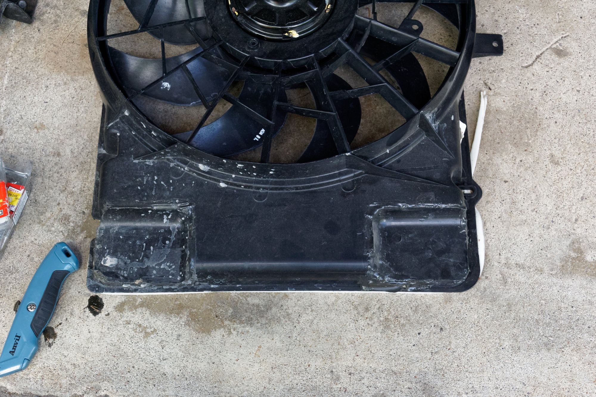
Others who have installed this fan cut out the top and bottom sections for radiator hose clearance. When I installed it, I decided to swap the corners (they are inversely shaped) and use some JB weld and scrap ABS to glue them in. This helps the fan remain effective when operational since it has to suck air through the rad, and not just circulate air in the engine bay through those openings. There is an opening at the bottom of the shroud which I left untouched, specifically because I was concerned about airflow at speed.
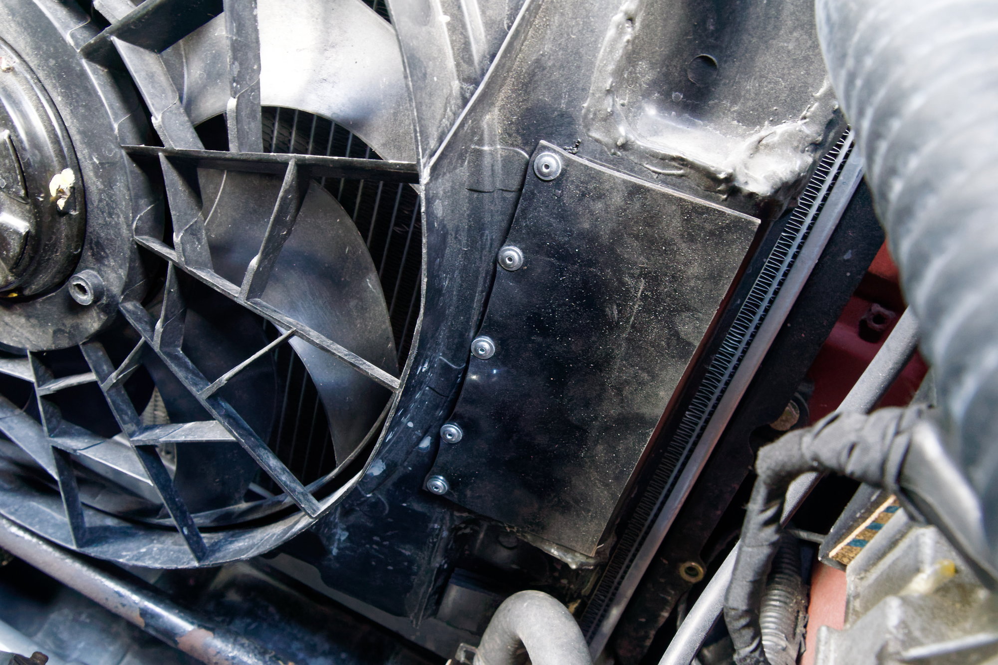
What I traded off in fan efficiency, I compromised in all-out cooling. I'm no airflow expert, but even a layman like me knows that the flow through the core is bottlenecked by the opening for the fan, since it can't escape through any other avenue. So I thought, maybe I should add a way for it to bypass air at speed but not do so at idle. It turns out radiator flaps are already a thing, but I'll be making my own since the only one I found available commercially was more expensive. Especially considering the commercial kit was just a flat piece of rubber and some rivets.
So I bought some flat pieces of rubber and some rivets. First step was to take a rough measurement:
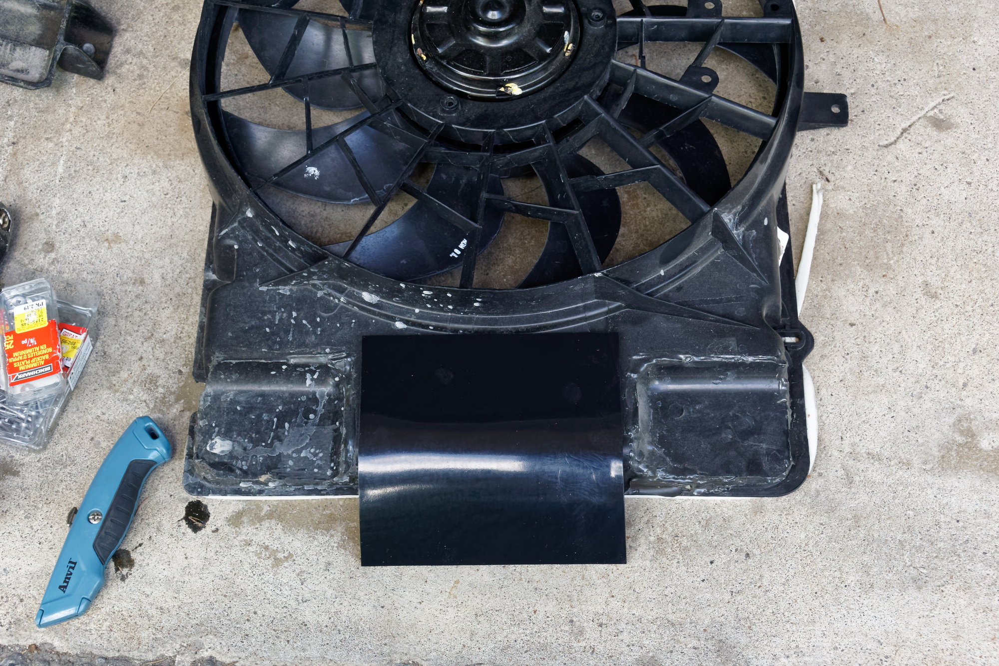
Make the cut. Precision isn't important, but there's about 1/4" flat on the bottom and sides and 1/2" on top. This way the rubber will rest against the flat brim, and the 1/2" is to give me space for rivets:
Added some rivets with those little rivet-washers (I don't remember the proper term):
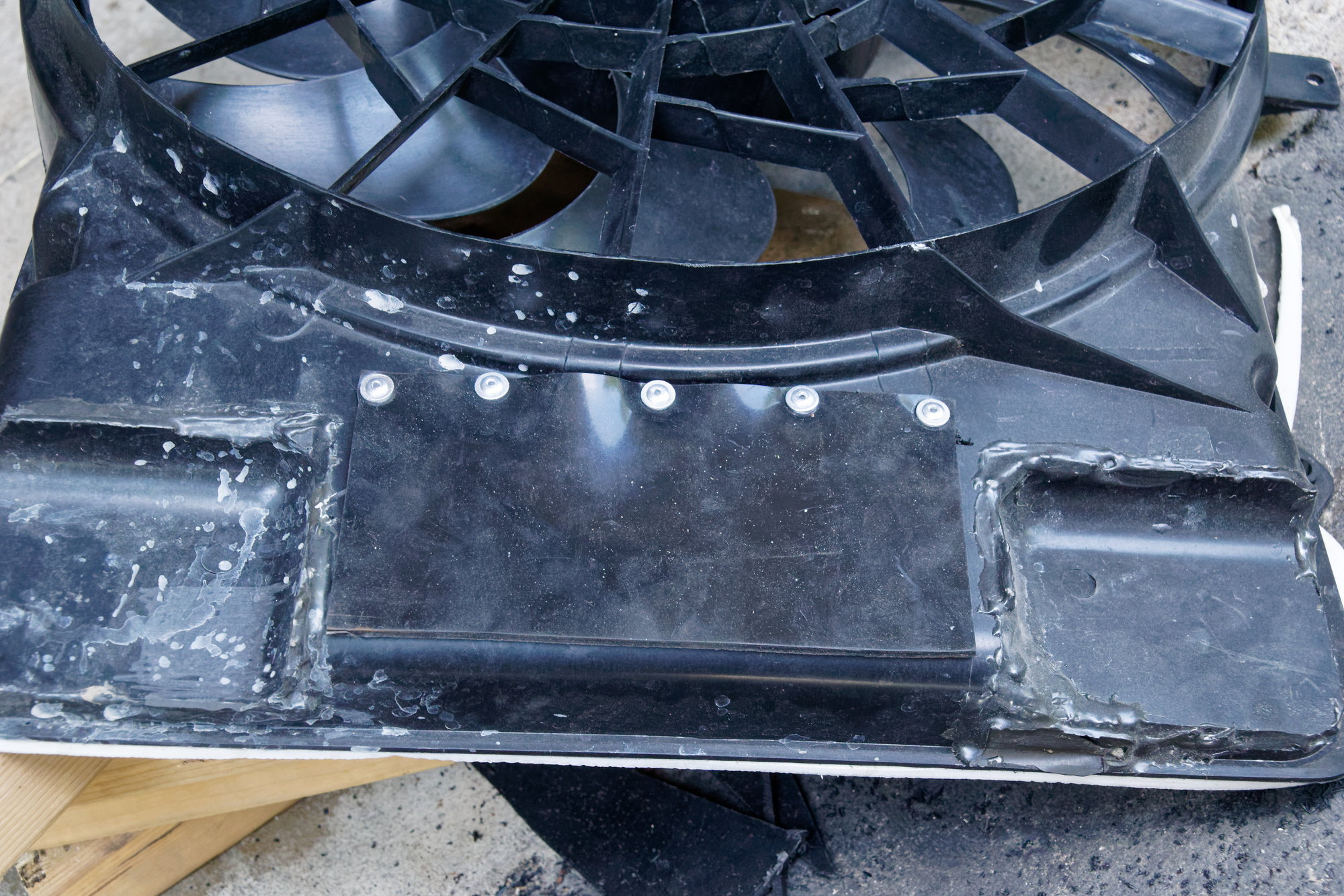
Then I installed it back into the car:
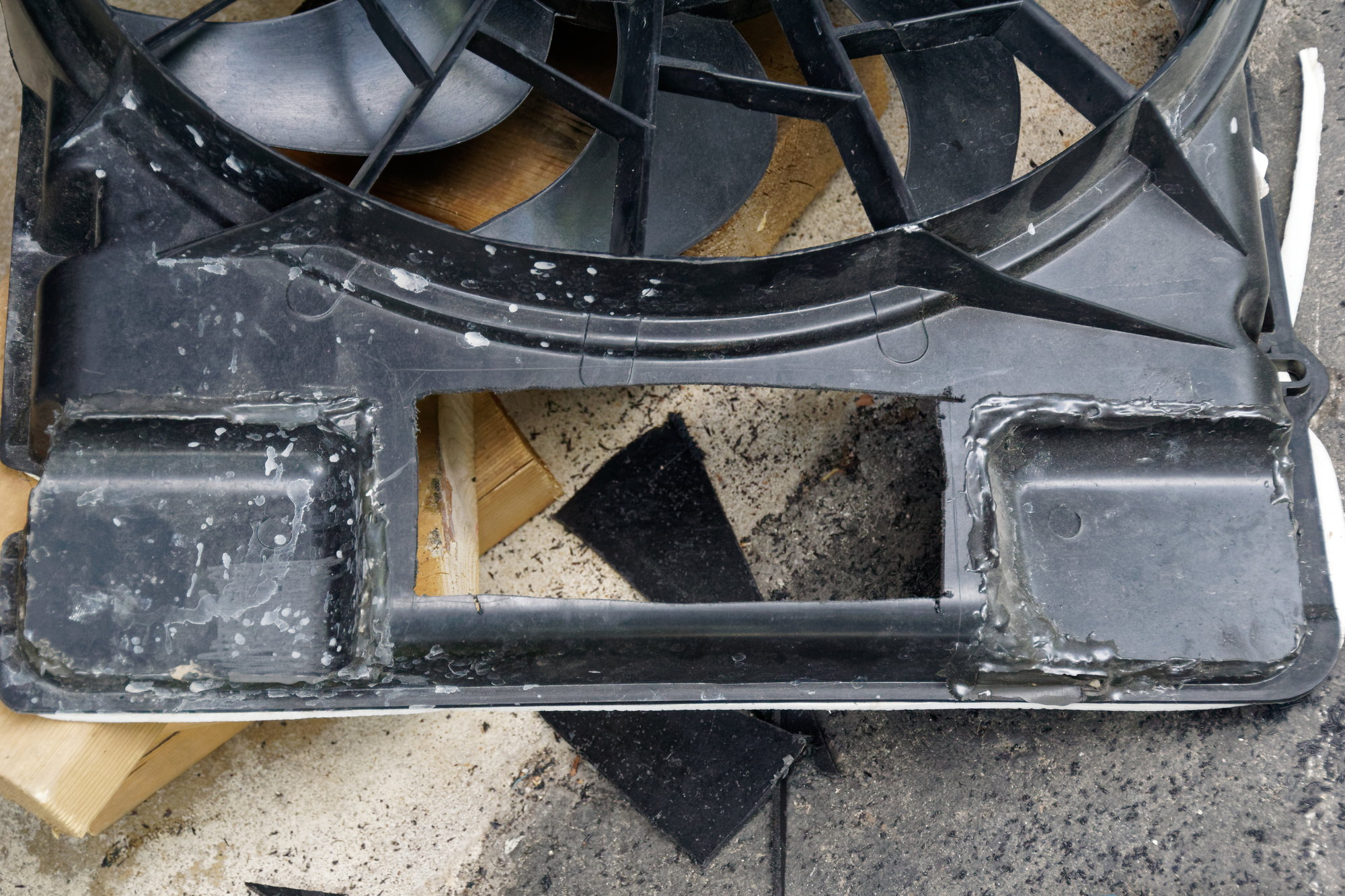
Then this is how it should work. When at idle or low speed and the fan activates, the suction inside of the fan shroud should hold the rubber flap shut, like this:
Then when at higher speeds and the fan is inactive, air pressure in the shroud from the air flowing through the rad should hold the flap open. Like this:
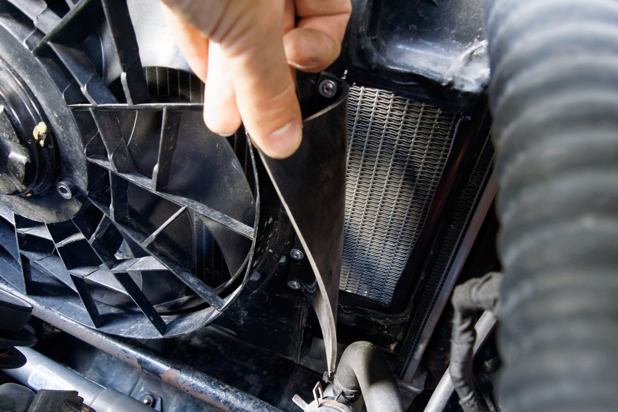
This gives the air a place to go when at speed, and should help cooling.
I took a test drive and found that under relatively similar conditions I was getting a 7 degree drop, cruising at around 187 degrees. MAT was cooler on my second drive though, so some of that temperature drop is probably unrelated. It's safe to say that it's dropped at least a few degrees, but I can't pin down exactly how much.
Long term, the best thing to do is to get serious about ducting. I'd like to get some more LRB pieces like the radiator panel and undertray. Since they're flat, it's easier to add foam to them than to the stock pieces. I have some sheet aluminum that I could use for the purpose, but the LRB parts are so nice I'd rather just save up and go with those. I could also make a smaller shroud with a generic round fan and try that out, but the Taurus fan works so well at idle and low speed that I'd like to retain it if possible.
For now at least, the car is still running within acceptable temperatures.
Until next time :)
I mentioned earlier that I had a transmission leak from the shifter housing, and had determined it was an “out of the car” job. I had intended to just keep parking on top of a piece of cardboard until the Turbo driveline swap, but then plans changed and a vacation got cancelled. This left me with free time to take care of the leak and a few other small things, so why not?
Forward section of the exhaust needs to come out:
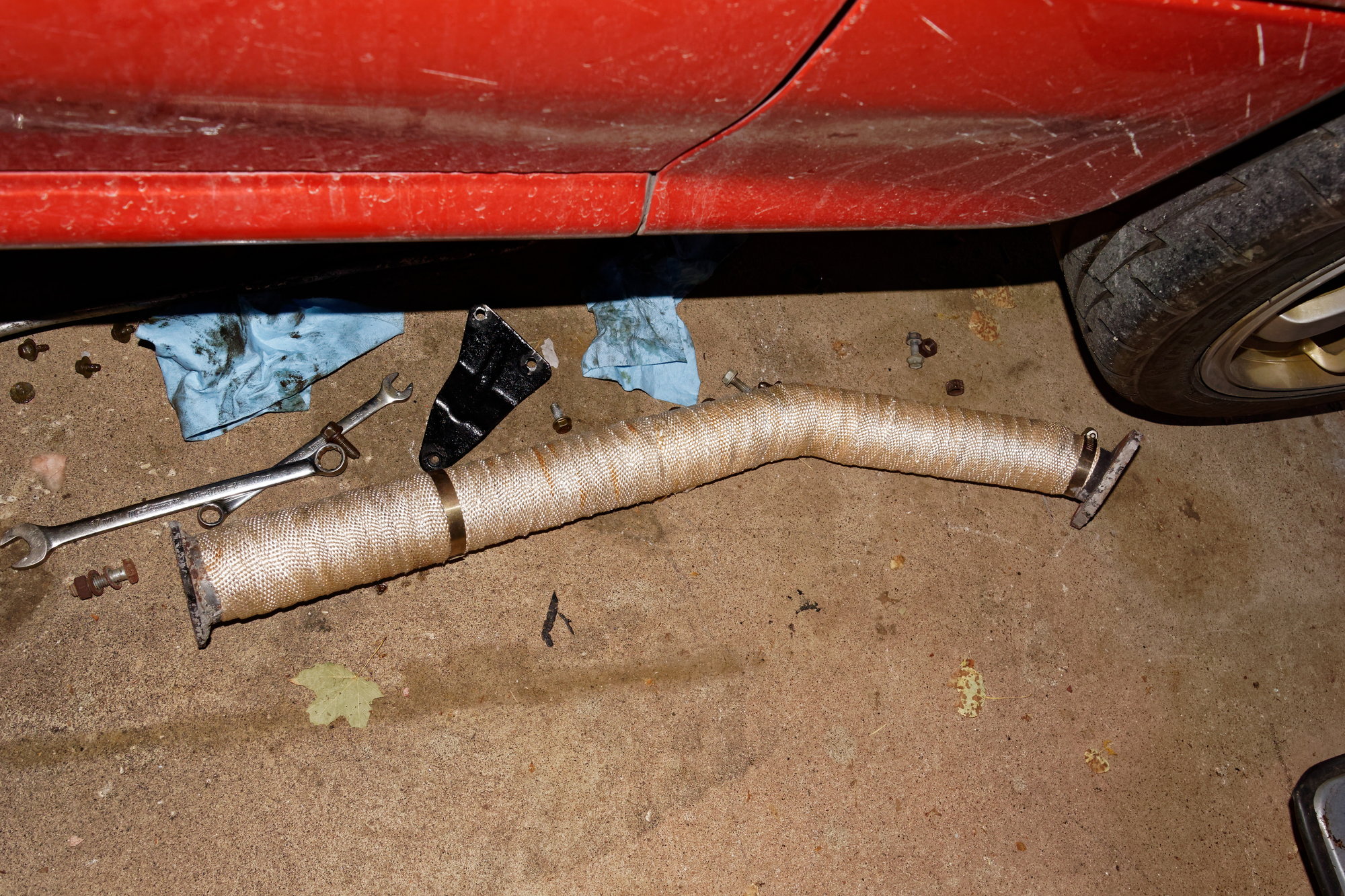
Catalyst:
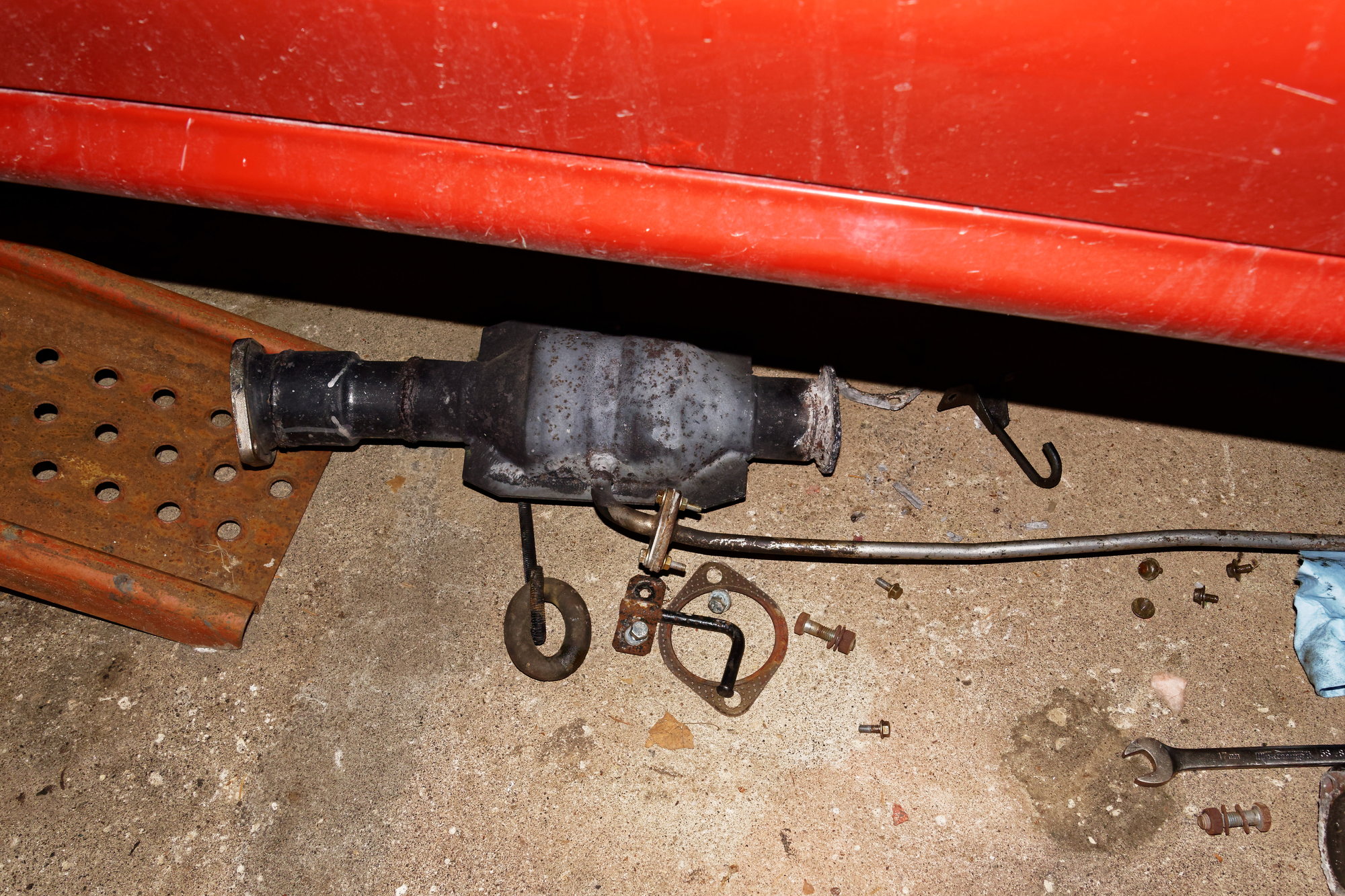
Shifter, starter, and driveshaft came out, and then the slave cylinder can be unbolted and tied out of the way. Next is the heat shield that goes between the exhaust and the transmission:
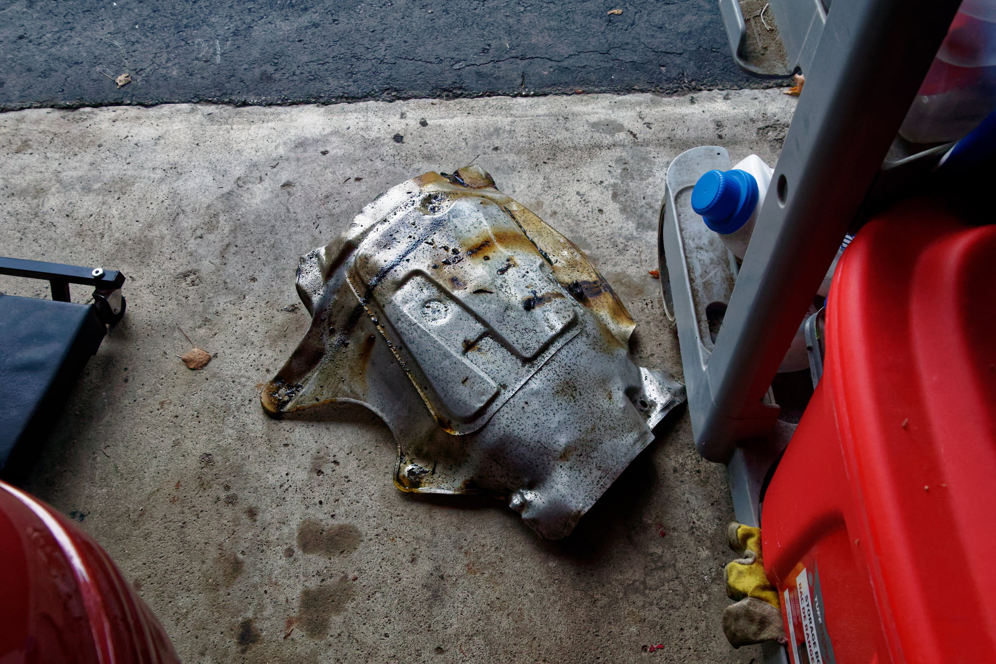
You can see the gear oil soaking the shield. One thing to note is the long linear deposit; this tells me the output shaft seal is probably leaking as well. Luckily I have a new one ready.
After that the transmission is ready to come out. Five fasteners at the engine, four on the crossmember, and then it just pulls free. I have yet to find a proper way to remove the transmission because it tends to hit the rear of the shifter opening and want to hang up. Jacks are clumsy since upward pressure to hold the transmission up fights you trying to pull the transmission back out of the engine.
My improper way is to just lay on my back, put my feet on the bellhousing, grab the tailhousing, and pull it down and out. Then just carefully lower the transmission down onto my body (emphasis on “carefully”) and roll it over and out of the way. The NA transmission is light so I can do this trivially, but the Turbo II transmission is quite a bit heavier. So when I do the swap I’m going to have my dad help me and use some jacks, no matter how clumsy they are.
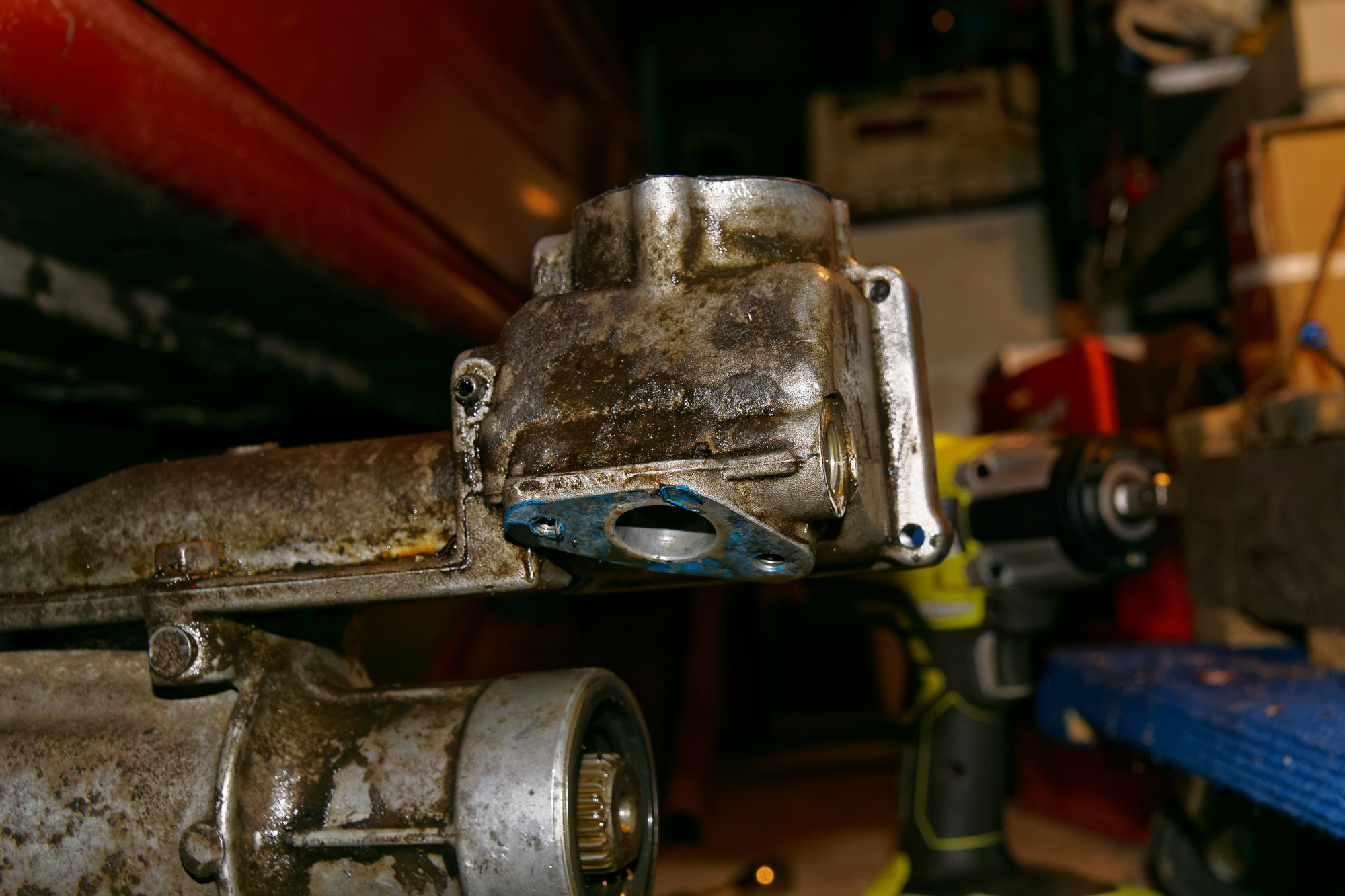
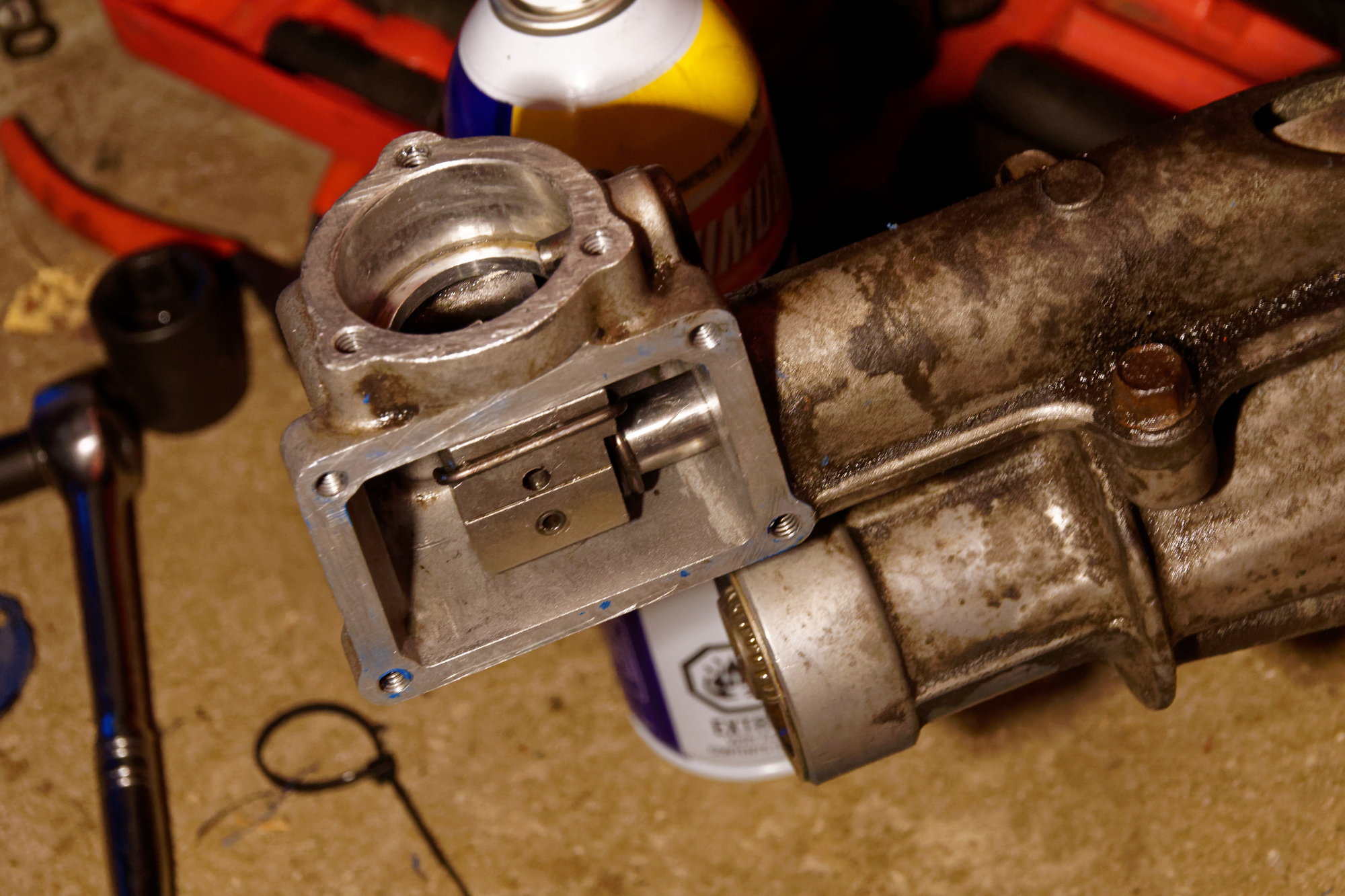
With the transmission out and pivoted to the side, we can see the shifter housing:
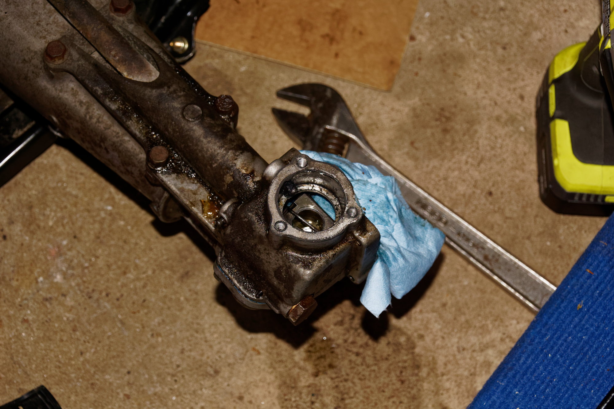
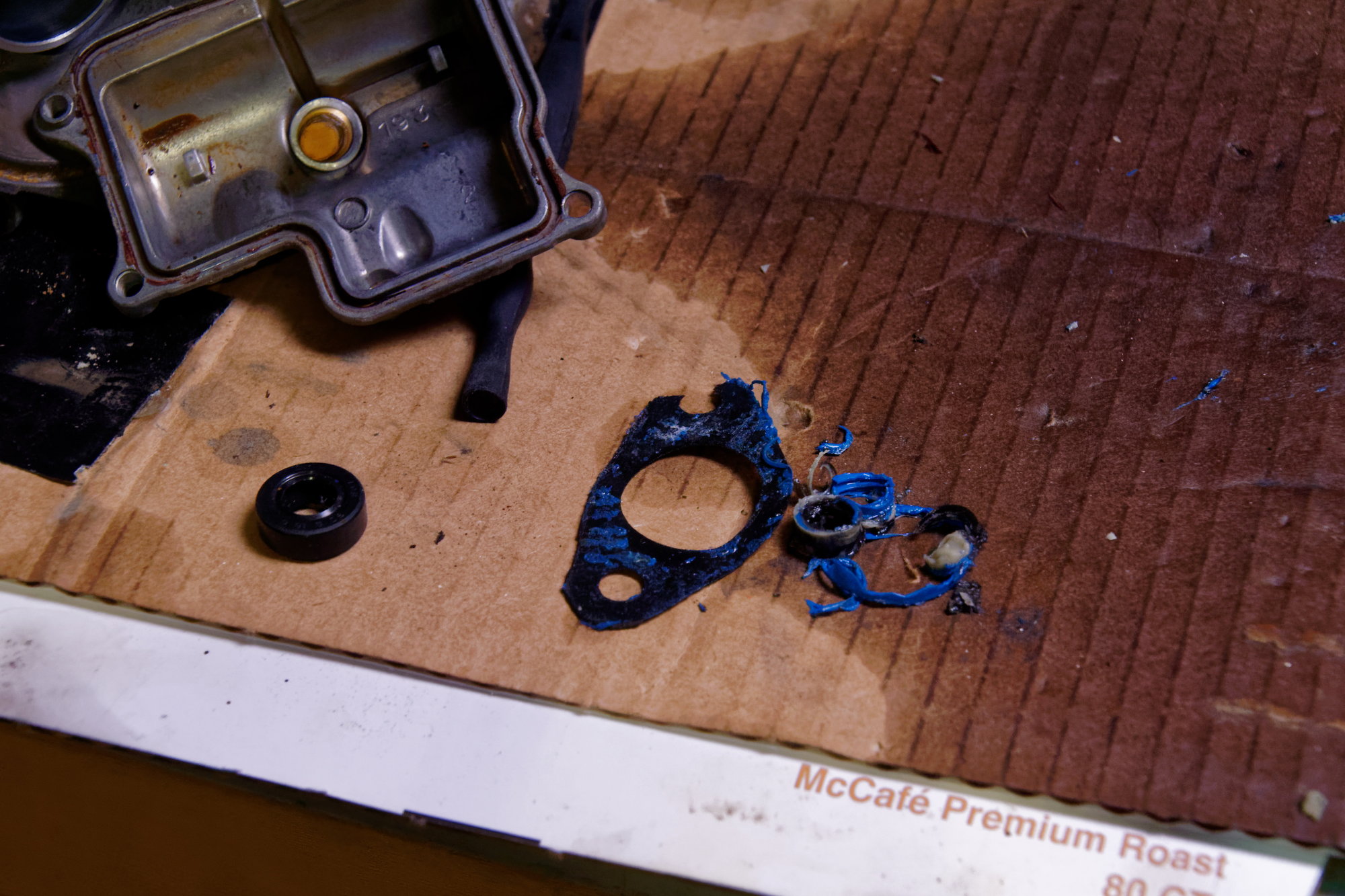
Yup, greasy. I took out the spring-loaded parts that make the shifter return from the 5-R area to center. Laid out like an exploded diagram:
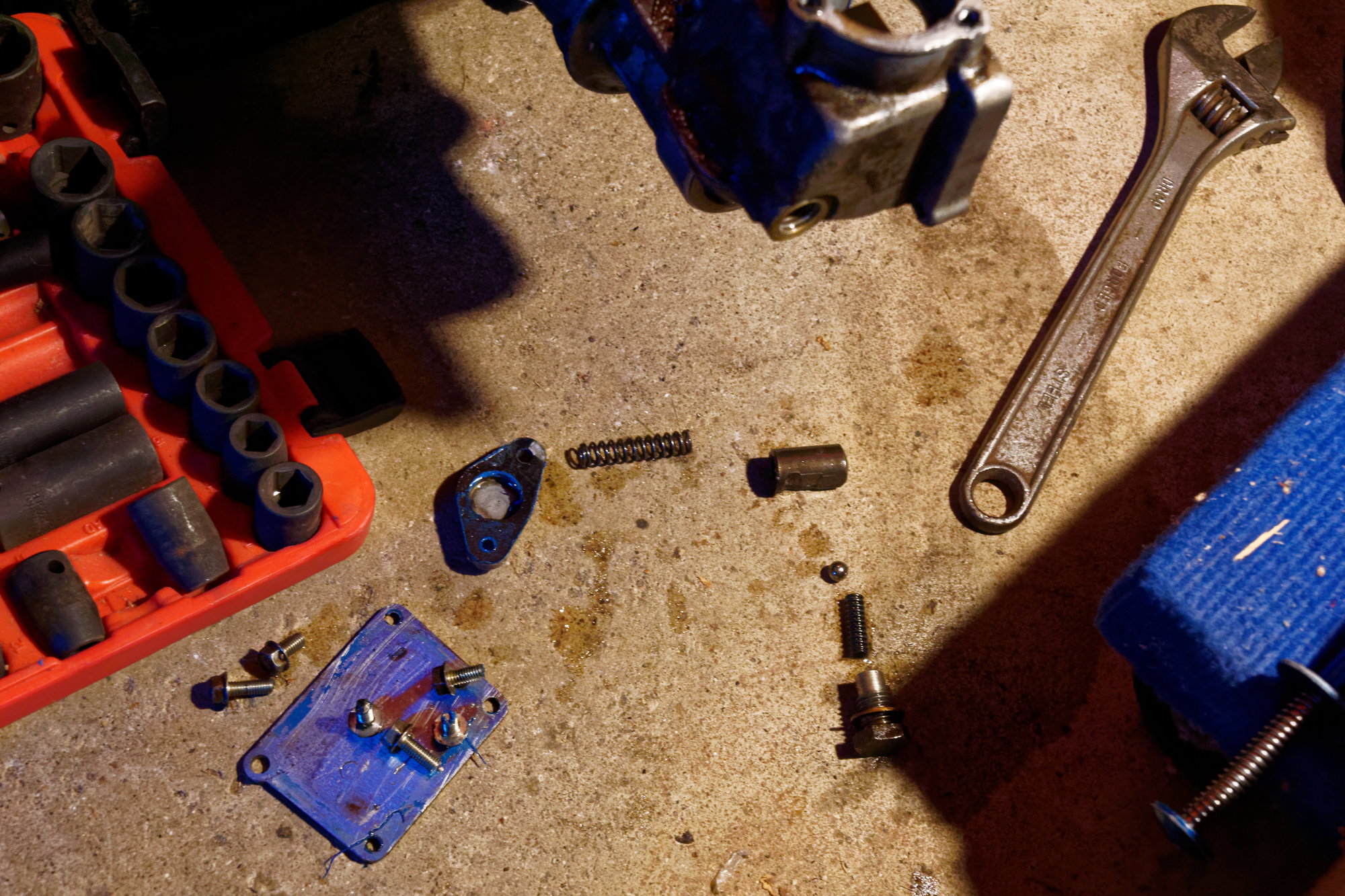
The plate, spring, and plunger with the steps in it are the parts that resist pushing the shifter from center to right. Then when you let go they spring back. The little spring and ball-bearing on the bottom hold inside the step on the plunger.
I noticed some blue RTV was used on the plate for the spring and plunger:
I thought it may have been myself that did that way back when, but then I saw this on the other side under the inspection plate:
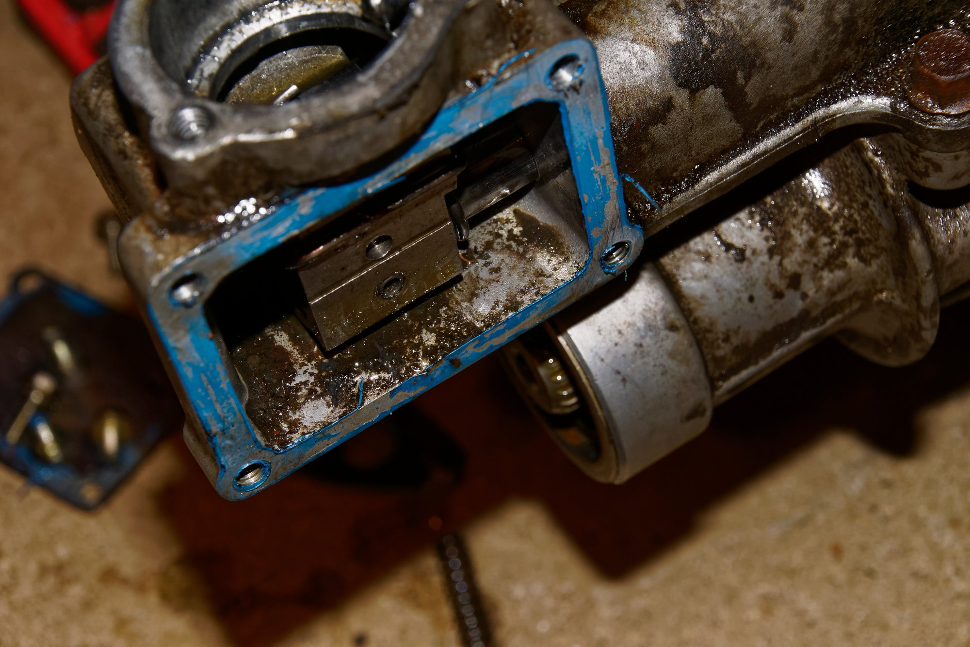
Yeah, no way that was me. I can see myself using the RTV, but I cannot see myself using RTV and not cleaning all that crud out from the housing. Looks like the dissolved remnants of the original shift bushings, plus some dirt?
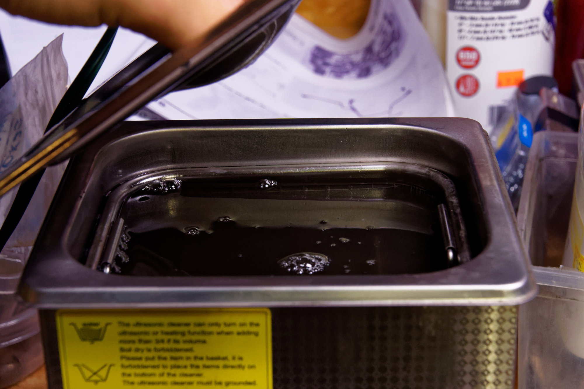
First I went to clean the small parts. My dad picked up a new toy that’s really neat; an ultrasonic cleaner:
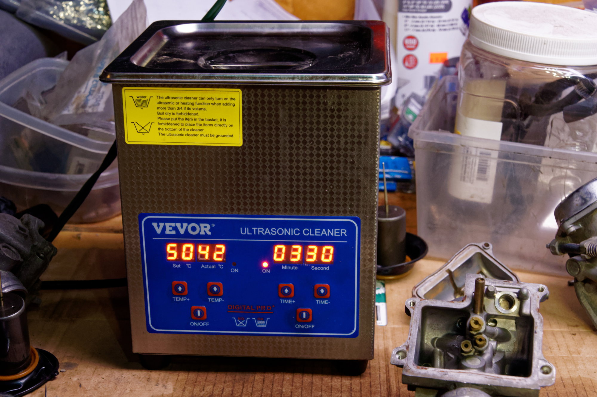
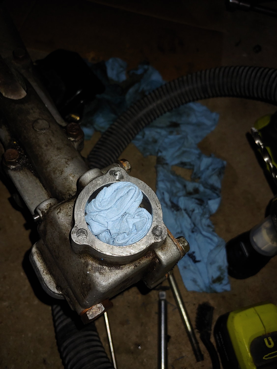
These things are cool. You toss in some parts, add liquid (degreaser, mineral spirits, kerosene, etc) and press start. It heats up the liquid bath and blasts the parts with sound waves to help loosen the dirt. I left that for a bit while I cleaned the shifter housing:
I cleaned the gasket surfaces with a razor blade and then used brake cleaner and scrubbed awhile. This was all the detritus that came off:
I also cleaned the speedometer cable seal by hand. I had to be careful not to lose it; according to my Mazda dealership I purchased the last one in existence.
To be continued.
Continued:
I finished cleaning the shifter housing, and came back to check out the fruits of the ultrasonic cleaner:
No, not the world’s worst soup. The parts:
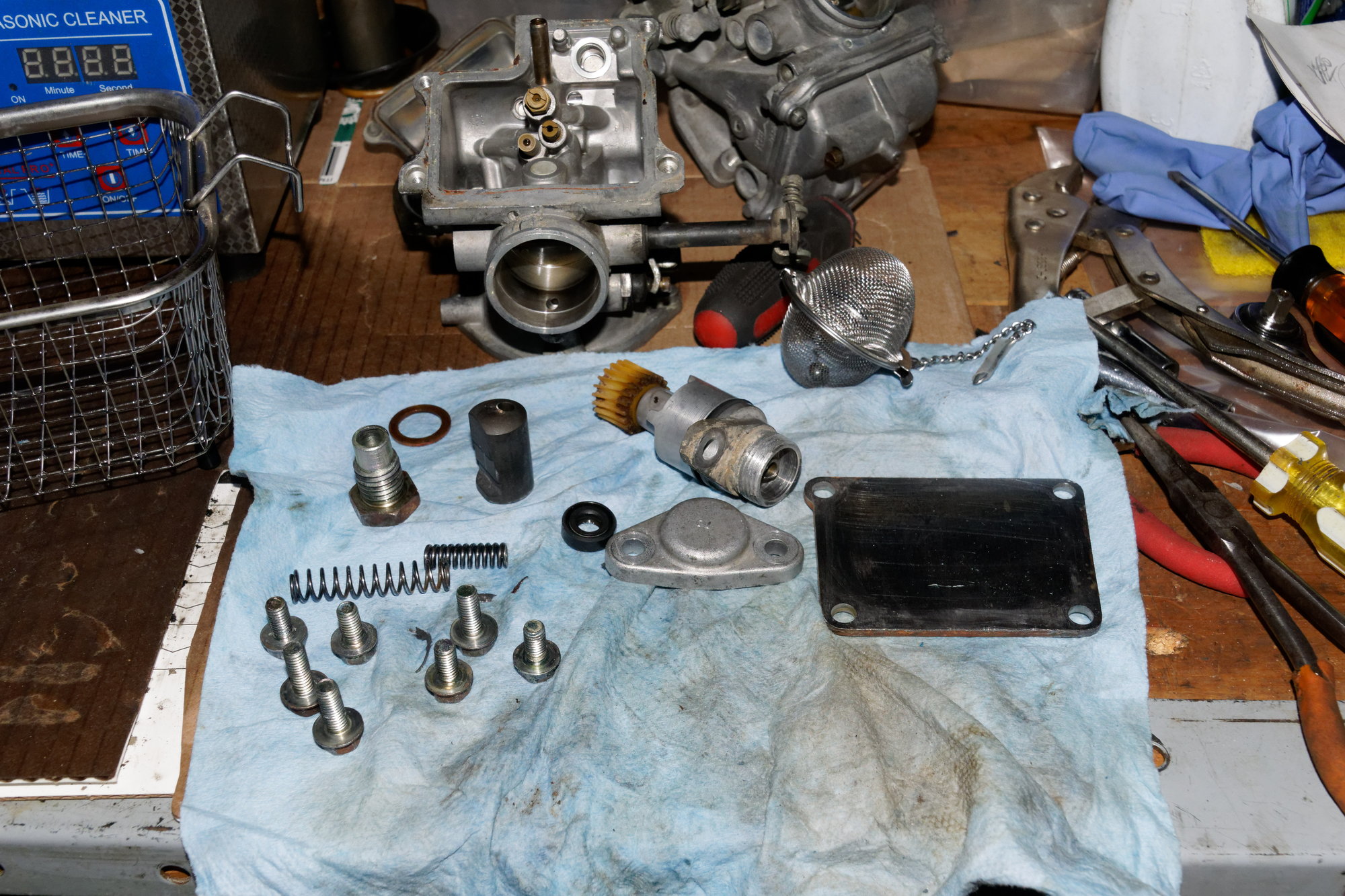
Squeaky clean. All I did was drop them in and then pull them back out. Even the RTV came off easily with a bit of elbow grease, which was a pleasant surprise. Everything went back into the housing in reverse order of removal, using RTV as I didn’t have new gaskets for these parts. I also popped in the new output shaft seal.
With the transmission out, it was an opportune time to repair some stripped threads on the shifter mounting hole. I have been babying it awhile with careful application of blue loctite, but it was time to repair it correctly. I’ve never used a helicoil, but these things are pretty neat.
Drill out the threads:
Tap with the special tap in the kit:
Attach helicoil to tool:
Then you just thread it in, and punch off the little tang on the end. I added some red loctite to the outside of the helicoil just to be sure.
Changing gears for a moment (ha!), I started to work on the exhaust. Awhile back I made a nice aluminum heat shield to replace the stock piece that had disintegrated years ago. I installed it on a spare manifold to verify fit, and that’s where the project halted. Unfortunately the manifold on the car had all the bolts for the heat shield broken off, and there was little access to remove them. So I just lived with it.
Having the transmission and exhaust already disassembled gave me an opportune time to swap in my spare manifold with the heat shield on it already.
I knew a mouse had made a nest in the spare manifold, but he wasn’t hurting anyone so I decided to ignore it for the time being. I was careful not to move the manifold from its place on the shelf so I didn’t disturb him. But today was the day to evict him, so I grabbed the manifold off the shelf and started removing the nest.
I assumed he wasn’t in there since I didn’t see him flee, but then I reached in and grabbed something crusty:
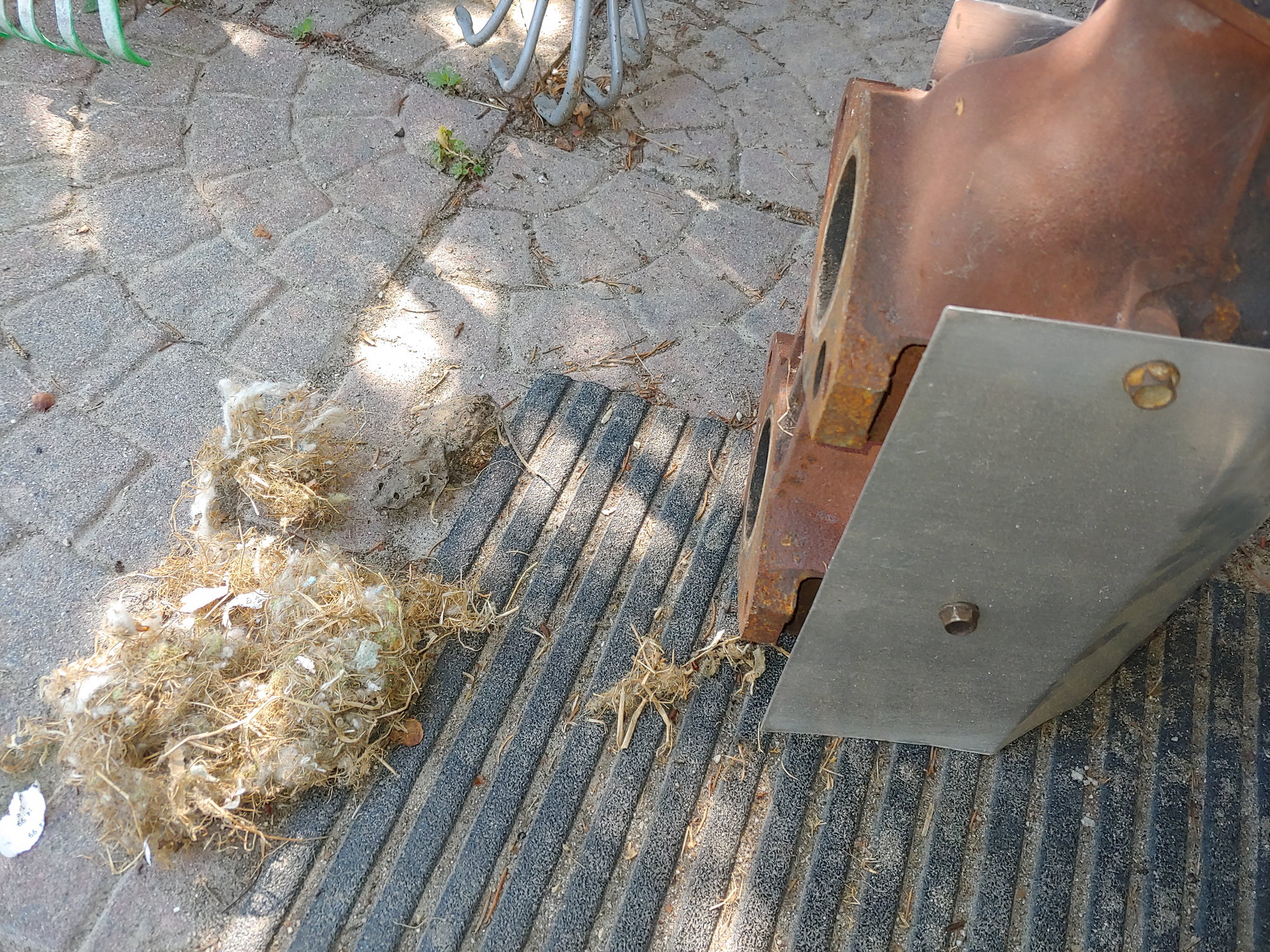
He died like he lived; Inside my exhaust manifold.
Here’s a better view of the heat-shield:
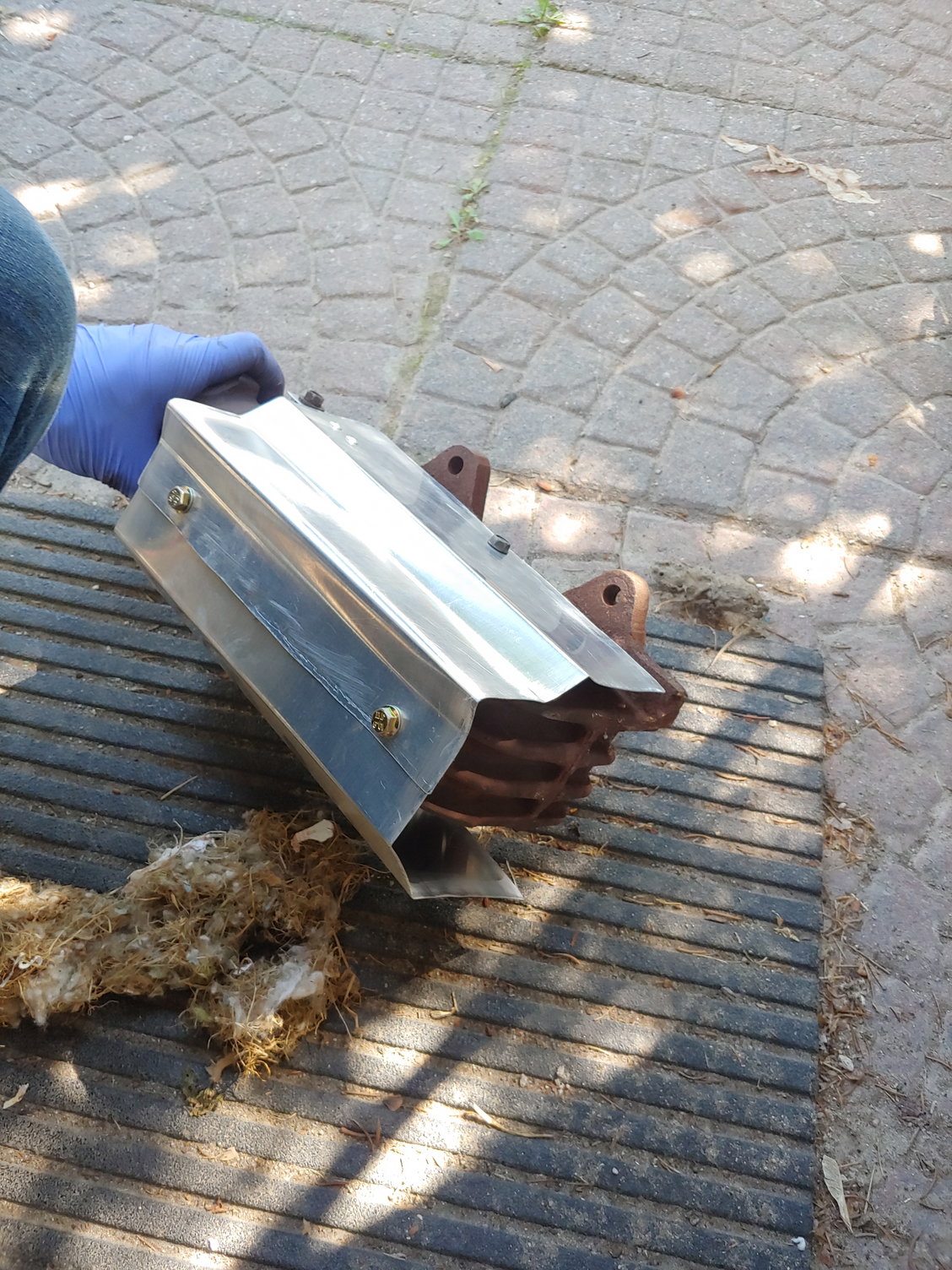
It’s just two pieces of aluminum cut to size, two rivnuts, and a couple rivets on top. Overall it should perform decently. Installed:
Then I put the transmission into the car and reassembled everything. Last was to fill up the shifter housing with fresh fluid:
Then I popped the shifter in and it’s good-to-go.
And it works. No pictures, since the car looks 100% identical to before. All I did was stop the transmission fluid leaks, and as an added bonus the orange exhaust RTV I used on the catalyst flange helped eliminate an exhaust leak. How long will it last? Probably not that long. In the meantime I’m just going to be happy with it and not worry.
The last thing I did was to add some foam to the radiator. I’m assuming that from the factory there was foam here already, but like many other parts, someone probably threw it away at some point saying “You don’t need that.” Just like people do with the undertray, the duct panels in front of the rad, emissions components, the thermowax, the idle valve…
I’ve mentioned before that I want to purchase the LRB undertray (and some of their other fine parts) and then use my spare sheet aluminum to make some proper ducts. I still want to, but in the meantime I just got some closed-cell door lining foam from the hardware store. I layered it a few times and then adhered it to the bottom of the rad:
Hard to see, but it’s there. A test drive showed no difference. Then I used some more to fill the void on the passenger side through which the body harness passes; no difference. Then lastly I filled the driver’s side void where the oil lines run…
Boom. Consistent 5 degrees F drop while cruising under similar conditions to before. As if that wasn’t enough, a 15 degrees F drop during an extended WOT run. I am currently averaging around 179-181 cruising, and peaked at 184 under extended load. I guess the last 10% of the foam really makes 100% of the difference.
I also found that the intake manifold is much cooler, probably due to the exhaust heat-shield and the decreased coolant temps. Granted I didn’t soak it in traffic for long, but after a 20 minute drive I could rest my hand on the plenum, which I have never been able to do before.
Hopefully we get a few more really hot days so I can test it under the worst conditions possible, but so far I’m very happy. Until next time :)


