
Storage Unit Rally Car Build - Week 13: Axels & Heater Lines
AXLES
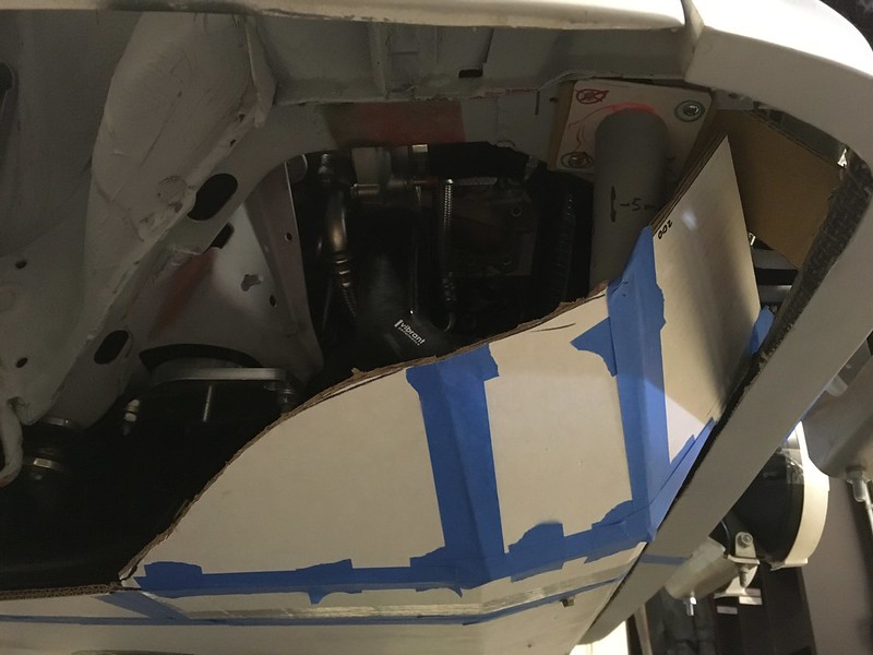
One day we are going to find a new building and will have to push this thing back out and into the trailer. With the axles out the wheel bearings flop about so we didn’t want to struggle with it again like we did, pushing it in. We decided now was a good time to reinstall the axles, even though we haven’t refurbished them yet.

Don’t worry, we cleaned them up a bit. We’re not peasants.
When we dug them out of hiding it soon became apparent that there were two long ones and two shorter ones. But where did they go, front and rear, left and right, where? It turns out, opposite corners!
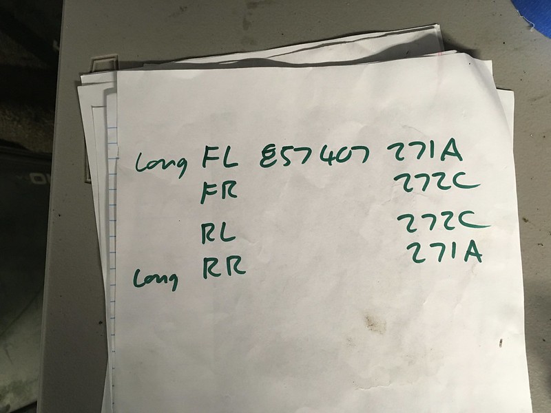
We’re sure there’s a good reason but just for giggles we did try to install one in the wrong place, just because, well, we’re idiots to be honest. It was too long.

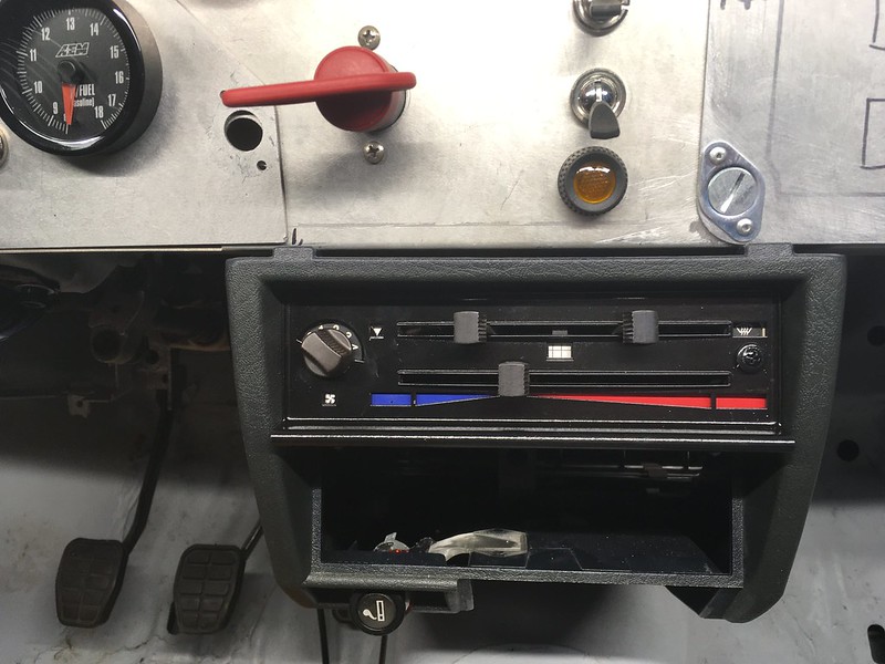
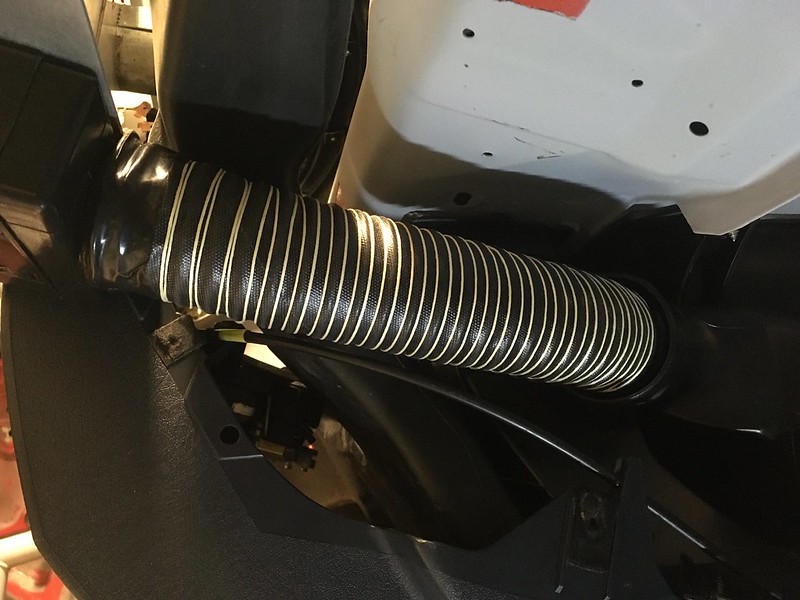
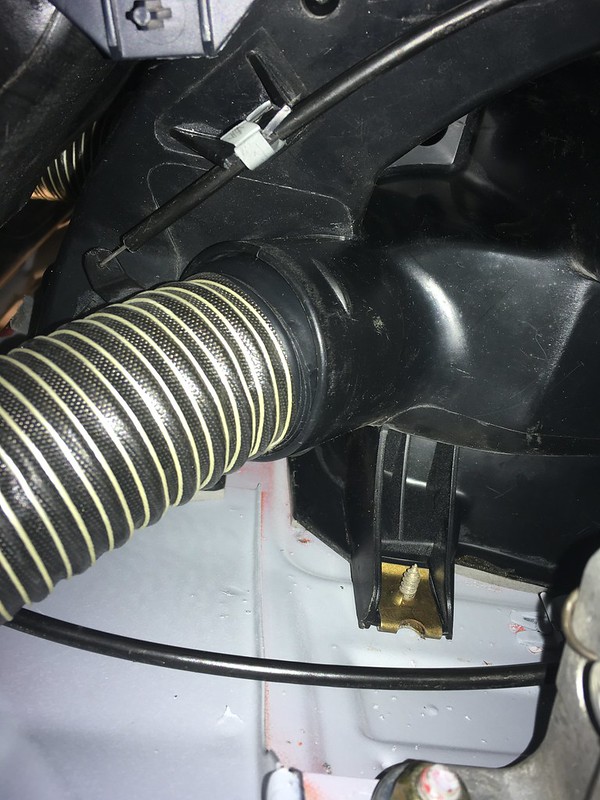
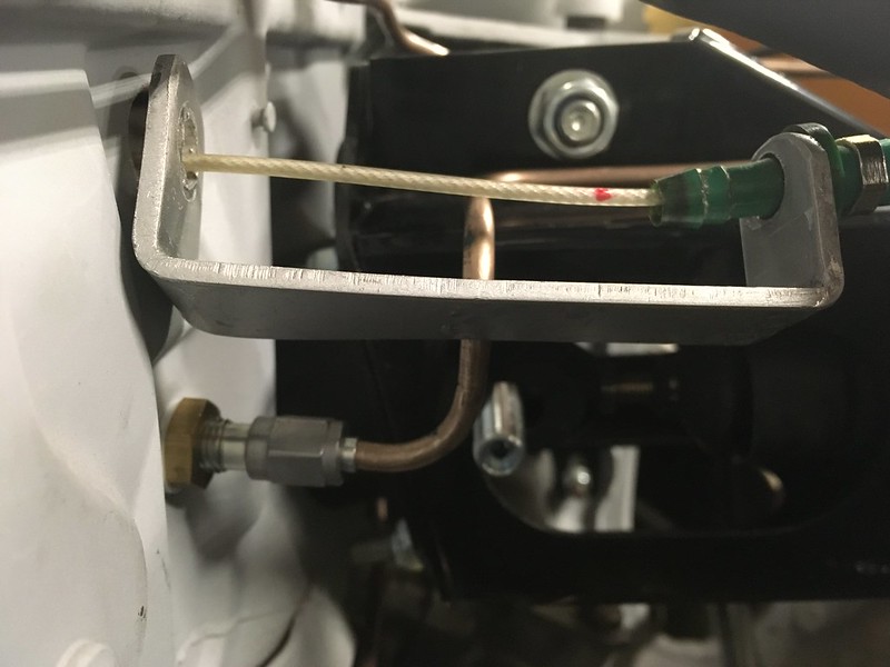
HEATER PIPES
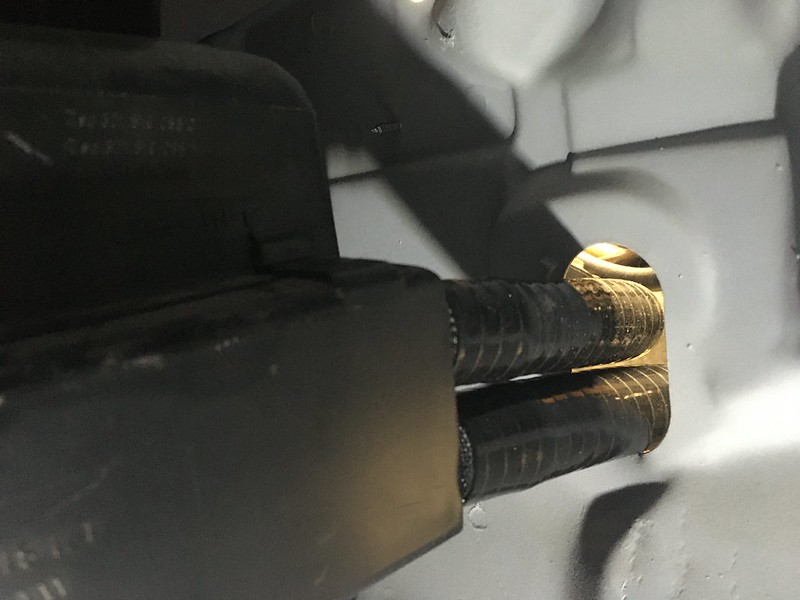
The 45* bends we were waiting for from Pegasus Racing came in so we got to finish heater pipe installation.

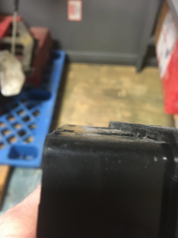
We’ve also located a brand new double grommet for the bulkhead!
Week 14 of the Storage Unit Rally Car Build
IACV (Idle Air Control Valve)
Yep, we’re now struggling to find things we can install while working in the storage unit. Picking at straws so to speak. Next on our list is therefore the idle air control valve. IACV. If you don’t already know, this ECU controlled valve bypasses the throttle at idle to allow it to, well, idle. Of course, with our fancy aftermarket intake manifold it won’t just bolt back in place. There is a connector for it at the back of the manifold be we’ll still have to tee into the intake tract before the throttle at some place. Here’s the valve with its rubber mounting ring and the nifty bracket that it sits on.

It is quite heavy so we think we should try to mount it using the OE bracket if possible. The inlet to the manifold is towards the back directly underneath, but whatever the IACV mounted off before is no longer apparent. So, we contrived a bracket extension off the engine mount arm as there were already three threaded holes in that. Engage CAD design mode.


We’re not really setup to make this in our storage unit so we’ll either make it later or outsource it. The inlet is a straight-ish shot to the back of the intercooler end tank but we’ll need to weld a bung on for it so, job stopped!
SEALS
Our searching through various boxes for various parts revealed the window and aperture seals so we decided to take inventory and install some because, well, we’re running out of things we can do and we have to keep moving forward somehow.
Door seals

Windshield seal

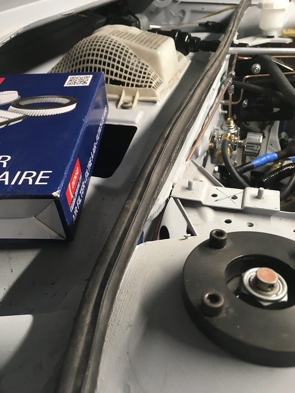
Under hood cowl seal
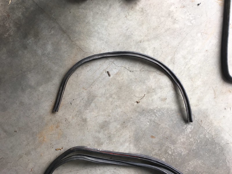
Trunk seal

The rest of the window seals are already on the respective windows hidden away, somewhere. These pieces seem to be still in good shape and were surprisingly satisfying to install.
Week 17 of the Storage Unit Rally Build: A Sharp Intake of Breath
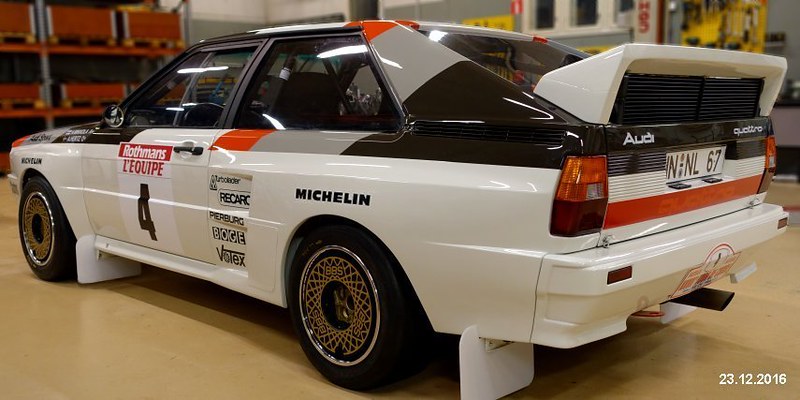
We’ve been back and forth on what to do about an intake system for the car for ages. We’d like to have our cake and eat it too but we just can’t see a way to get there. This is what we’d like to have:
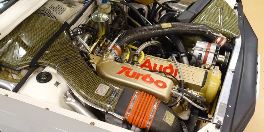
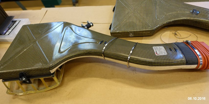
As used on the works rally cars. It looks iconic and sucks air from the high pressure cowl area where, conveniently, there are louvers in the hood above for that very purpose. There are a few problems with this. Firstly we have a MAF sensor to incorporate in the intake track, ideally in the stock location as we have an aftermarket U shaped intake tube that houses connections for all kinds of other bits and pieces that we need. This really doesn’t mate up to that.
Secondly, if we did this it really would have to be made of carbon Kevlar to pass muster and making one from scratch would be very expensive and time consuming. You can, in theory, buy one but we’ve heard it’s of dubious quality and it still wouldn’t mate to our MAF sensor.
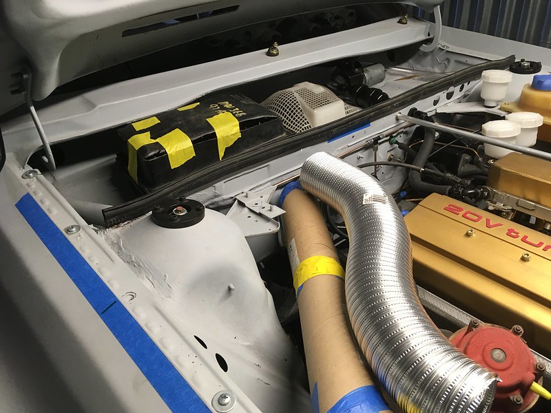
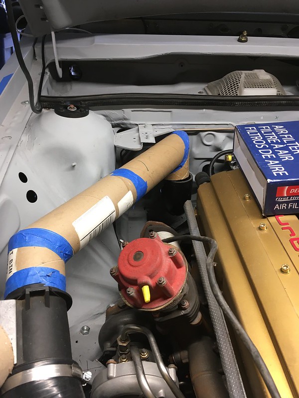
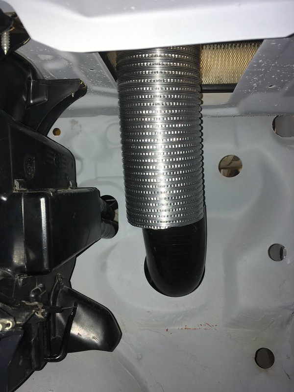
We tried prototyping an alternative route to the cowl that goes down the bulkhead to an existing 3” hole before doing a 180 into the passenger compartment and back up through another existing hole in the cowl. We think we could terminate this into an oval shaped pancake filter with a lid. It would probably work and we think we could make it look half decent but our fear is that it would just look like a poor substitute for the original.
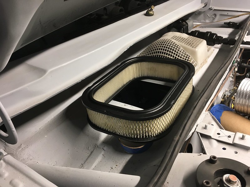
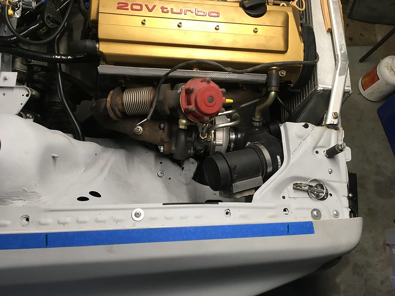
We could just whack a bloody great cone filter on the end of the MAF sensor and declare “job done” but there are a few problems with that too. It would be sucking air from right next to the turbo and also be right under the hood louver that lets hot air out of the engine bay and, not great, water in. So we dismissed this too. Here it is mocked up with a small filter.


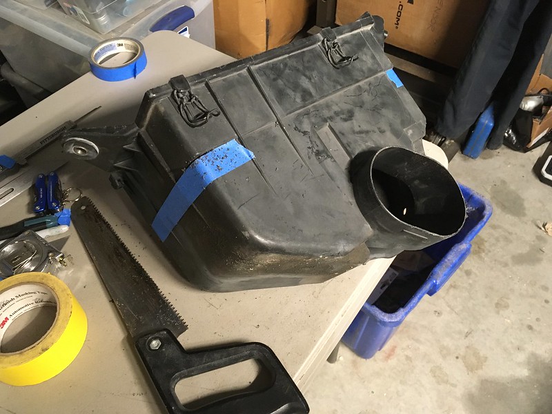
We looked at modifying some OE intake boxes but they don’t seem to be suitable either.
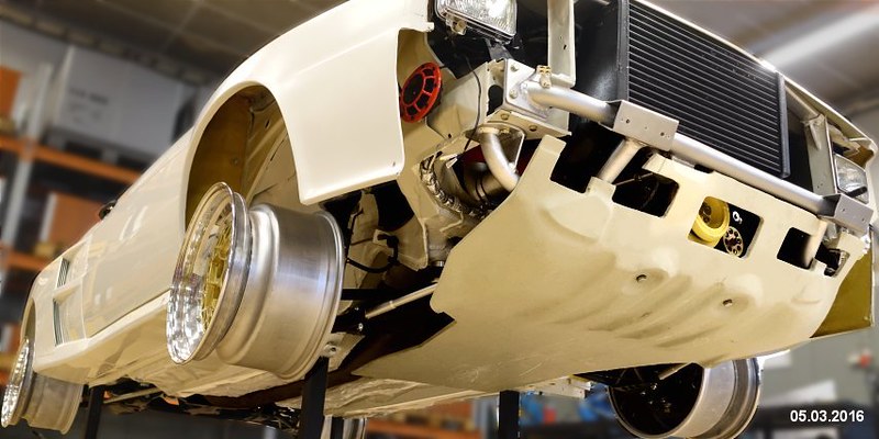
So we’ve settled. Settled on another U bend with a cone filter behind the headlight. This is not under the louver so should stay dry and it gets a good cold air feed from the grill and light surround. We also think we can shield it from the engine bay quite easily and, although it is a bit rigged it will hardly be visible so it doesn’t matter if it looks it.
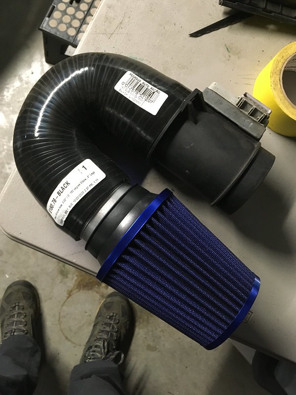
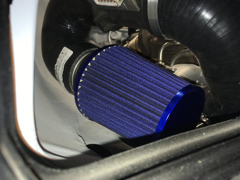

If nothing else it will do to get the car running. Maybe we will revisit this later, or not.
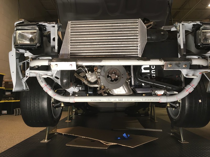
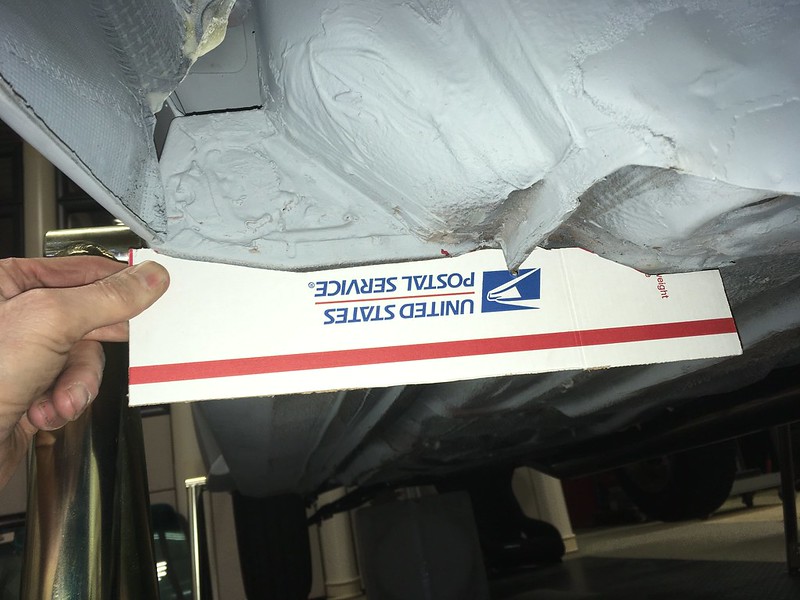
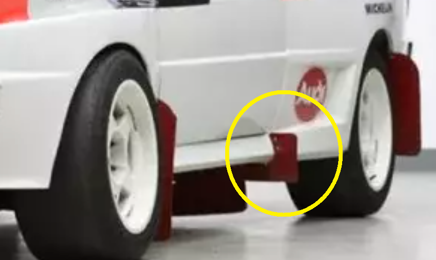
Prepping for Custom Stainless Exhaust and Skid Plat Design
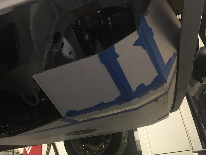
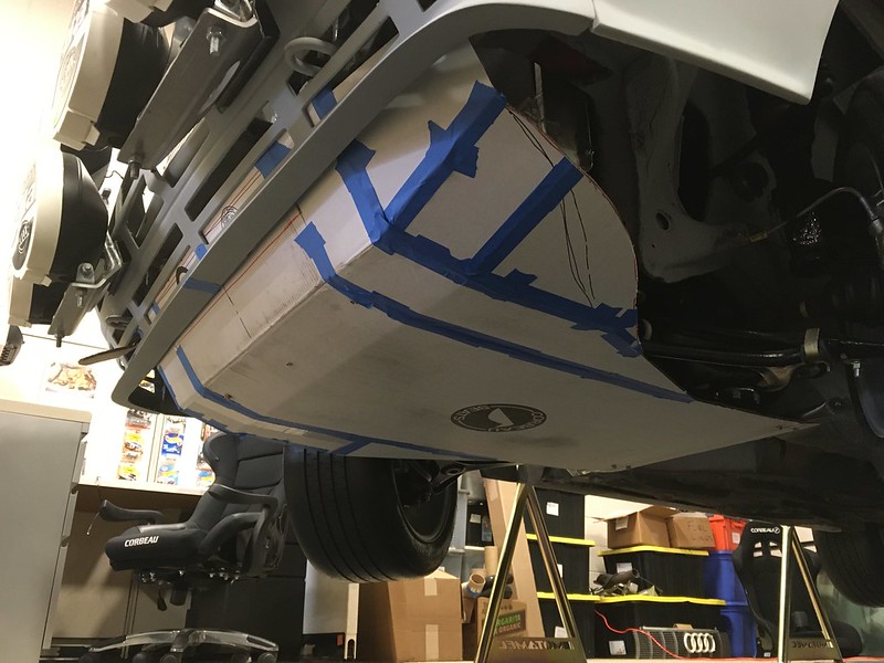
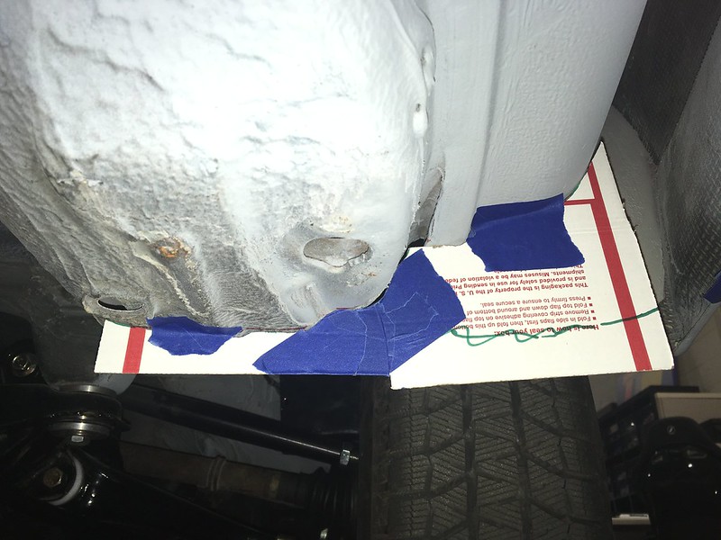
We are honored to have a friend of ours agree to build us an exhaust. It’s going to be 3” stainless steel with one muffler at the rear and as similar looking to the works cars as possible. Of course, that meant we had to build a skid plate! Well, not exactly but we did need to see how much room we would have around it so we mocked one up.
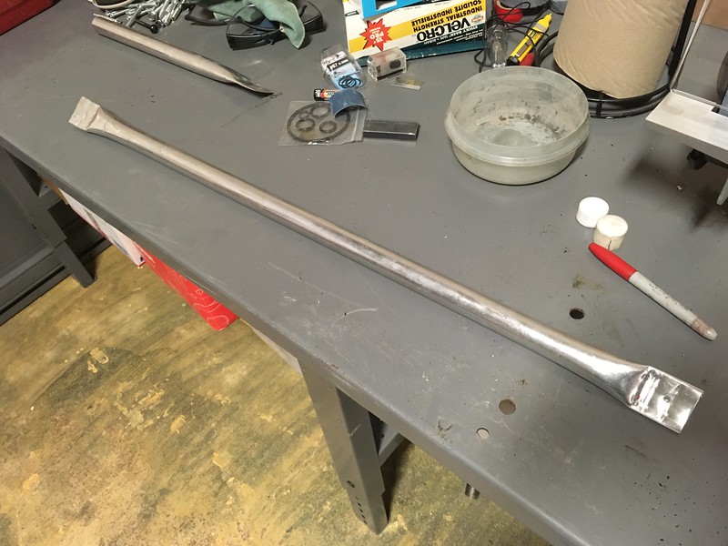
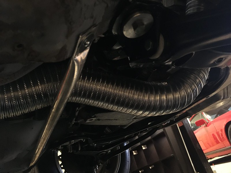
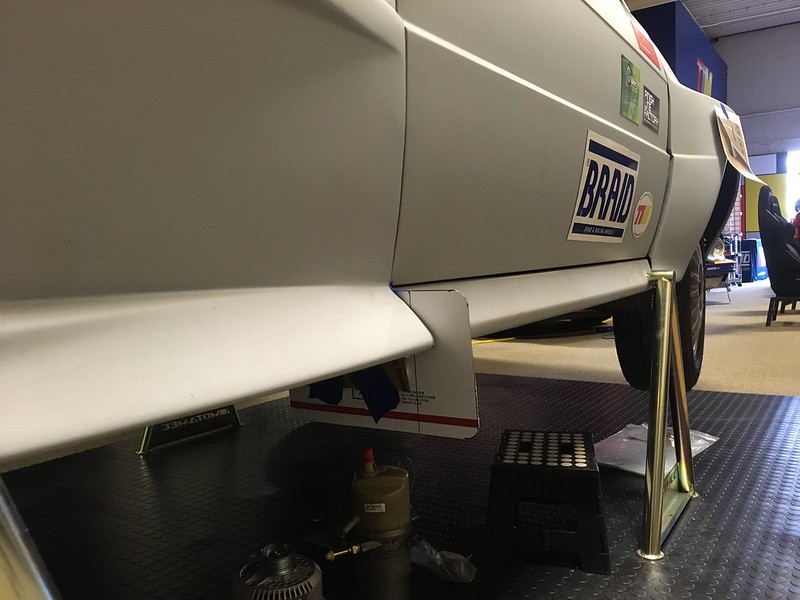
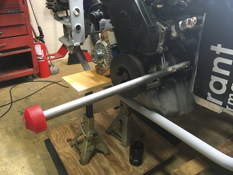
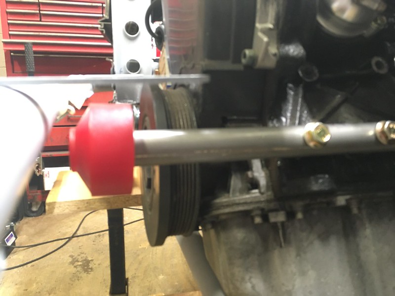
First the rear support bar which spans the chassis rails behind the gearbox. We used some rather flimsy aluminum tube we had lying around which made it really easy to flatten the ends.

Our surrogate 3” exhaust tubing fit through but it might need to be lower.
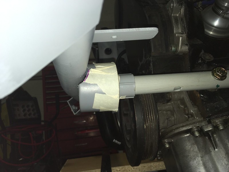
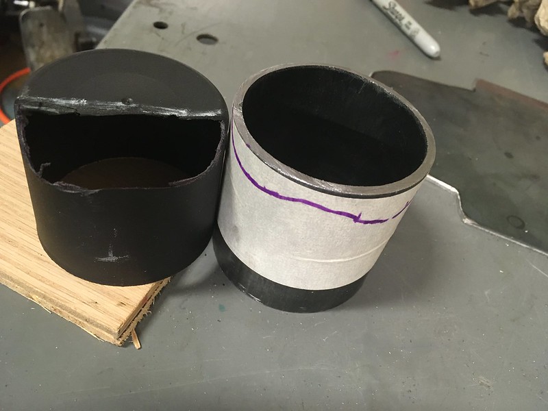
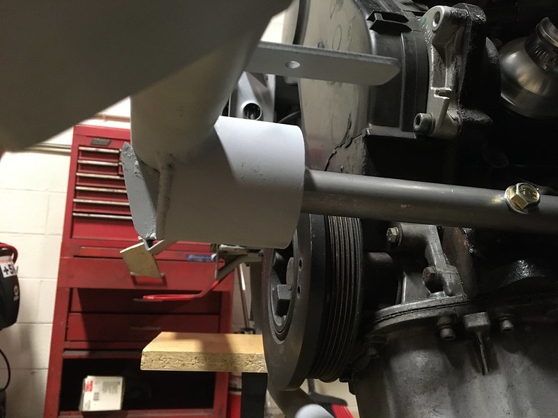
Next, we turned our attention to the front support. We thought we would see if we could mock up a reasonable facsimile of the works support using PVC conduit, even though that would be a little larger diameter than the steel tube we’d ultimately be using. How hard could it be?


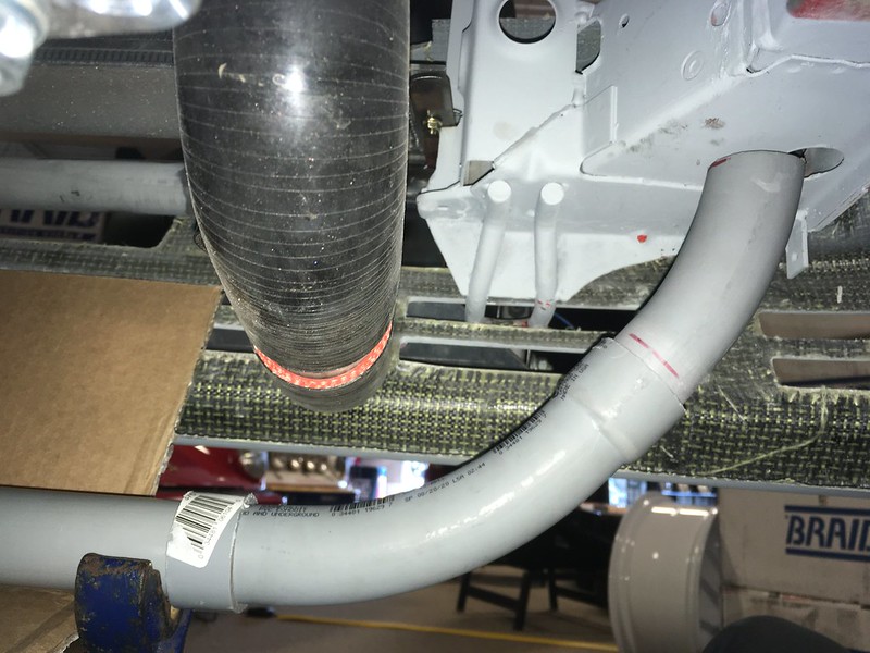

Not bad eh?

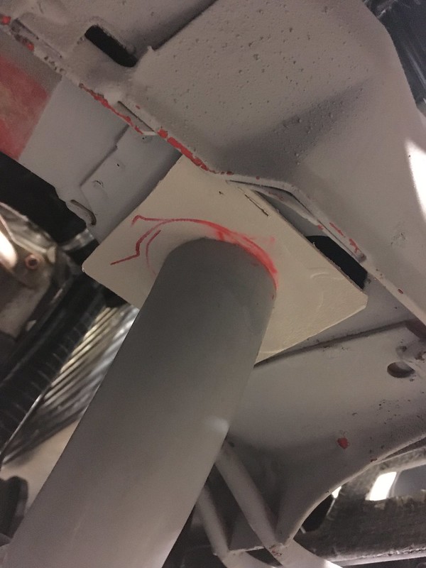
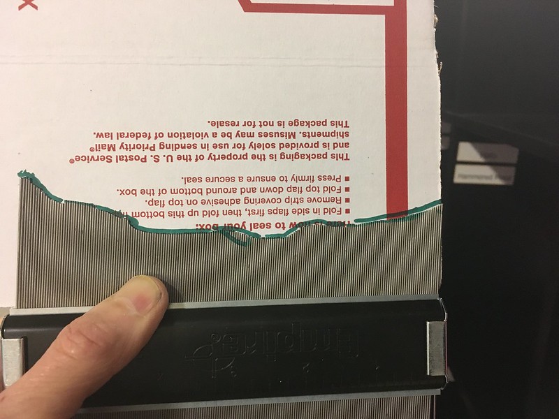
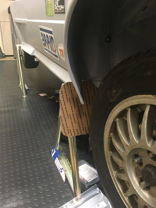
Next, we need an actual plate. Fortunately, we are a Corbeau seats dealer and their seat boxes are perfect for mocking up skid plates. Our plan was to try to replicate the molded Kevlar are whatever exotic material this one was made from, but in aluminum plate. This might be a three or even four Hobnob project!
Well, you don’t know until you try so we put the kettle and our thinking caps on and had a Hobnob. First, we made a masking tape mold off of our 1:18 model. Then we put that on the photocopier and hit x18! (no, we didn’t)
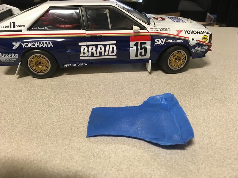
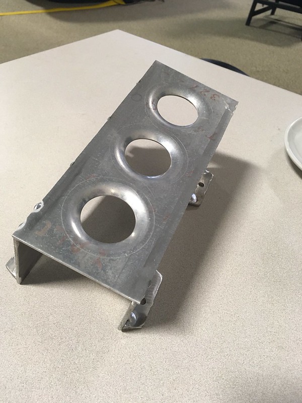
As convoluted as the works plate appears, if you study the it carefully you can make out many flat looking facets to it. Most obvious is the center section that is about two feet wide. We realized that if we took a long piece of box this wide and put two bends in it we would have the essential structure down. Moreover, if we weld some 2” wide rims on it might look quite similar. So that’s the plan.

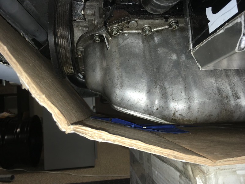
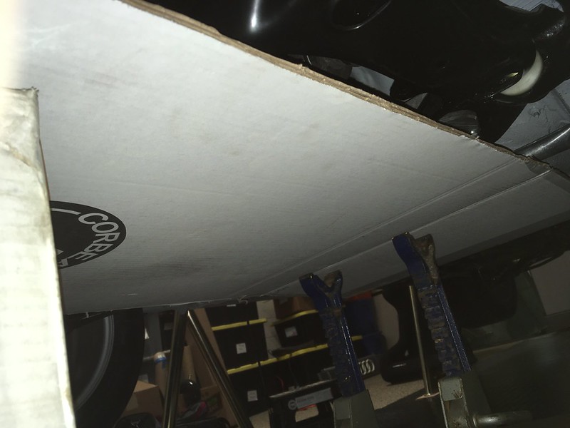
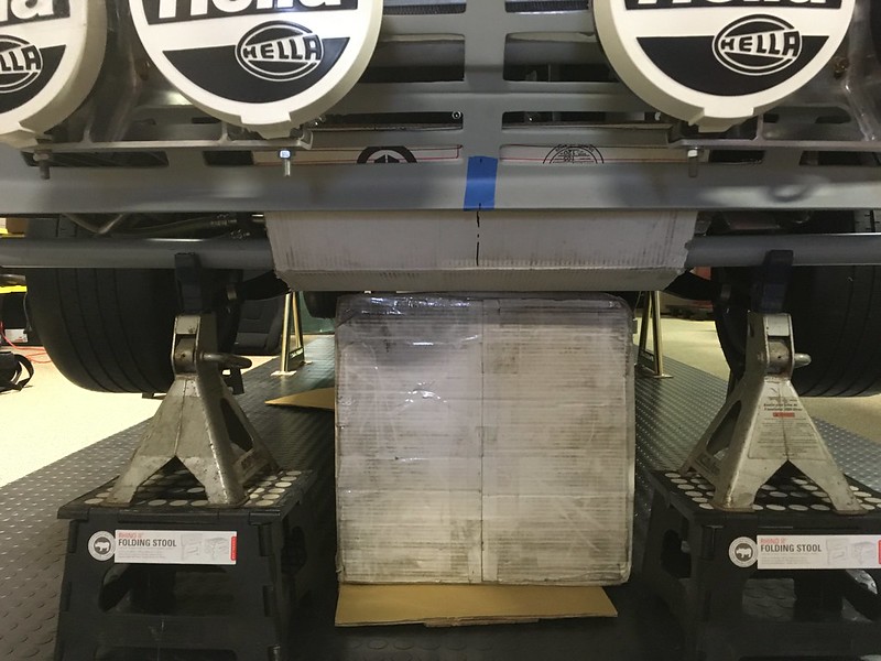
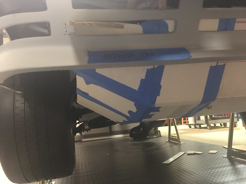
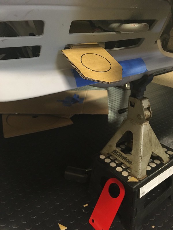
We were pretty happy with this so far and decided that maybe this idea had some legs. We pushed on with mounting the cardboard plate to the PVC support bars so we could remove the box and axles stands. To do this we made some clips out of some thin aluminum sheet and bent them around the bars. They worked rather well unless there’s a slight breeze or somebody sneezes too closely!


So that was the basic structure sorted. Now we just needed to widen it; and form the upturned sides! A bit more Corbeau cardboard and loads of Hobnobs and Yorkshire tea later we had this:
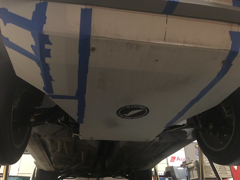

Lovely. Right; what shall we work on next? Mud flaps? First, we’ll have to put the kettle on!
Solid modeling was the major CAD advancement made in the 1980s. Significant software offerings included the well-known 2D system known as “AutoCAD.” We’ve been doing a lot of Auto-CAD ourselves lately but the more grassroots Cardboard Aided Design versus the Computer Aided Design you might be more familiar with. Most of what we are cadding is to make templates for a bunch of parts we need to fabricate most of which involve welding.
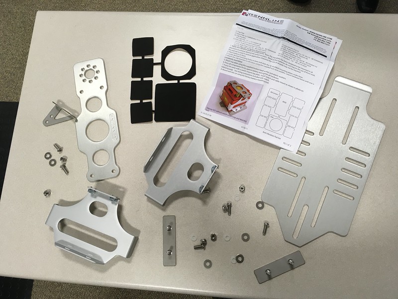
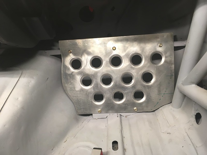
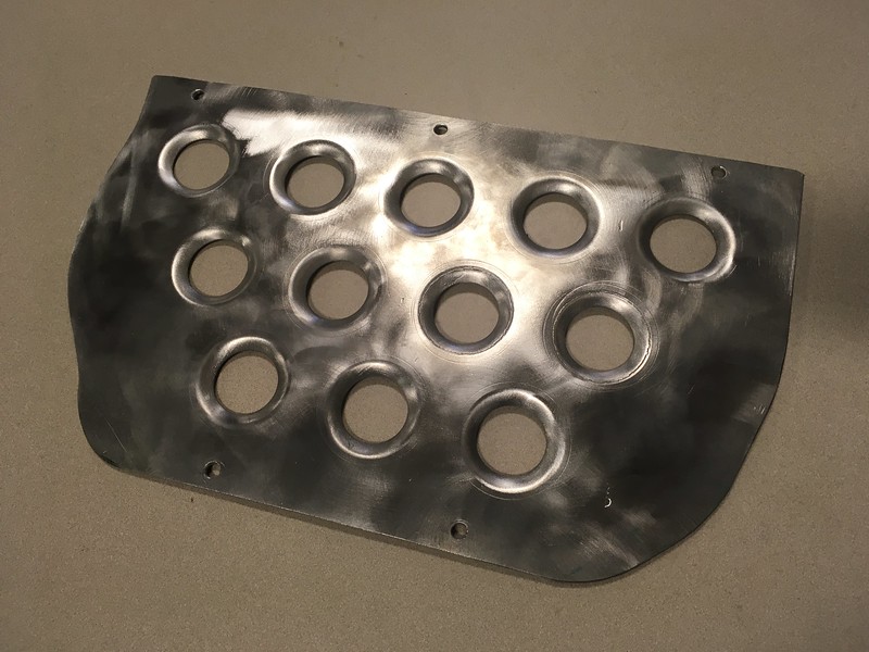
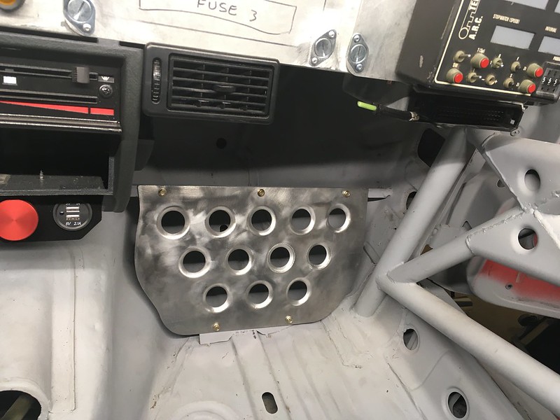
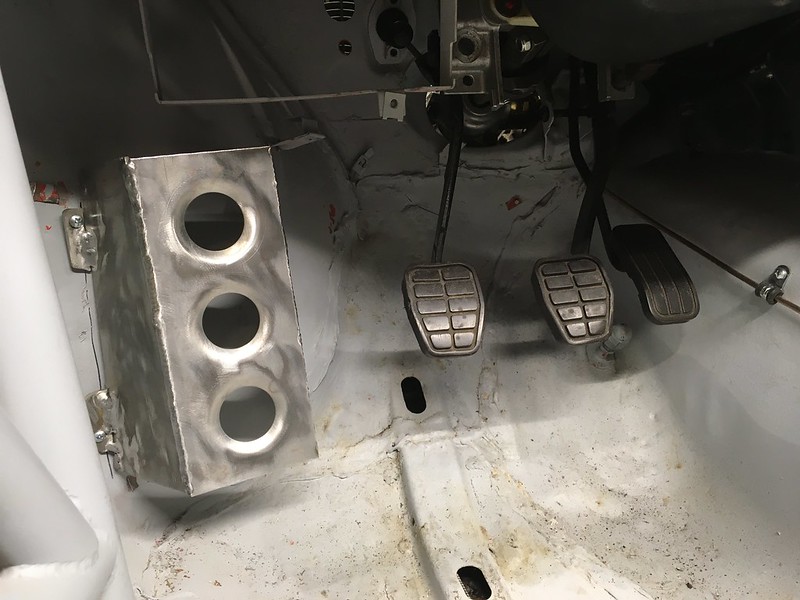
We started with the simple stuff; the foot rests. Yes, you can buy generic ones which work just fine but, you know, we saw that Group B restoration build and now we want those, or as near as we can “reasonably” make.

And the driver’s dead pedal:
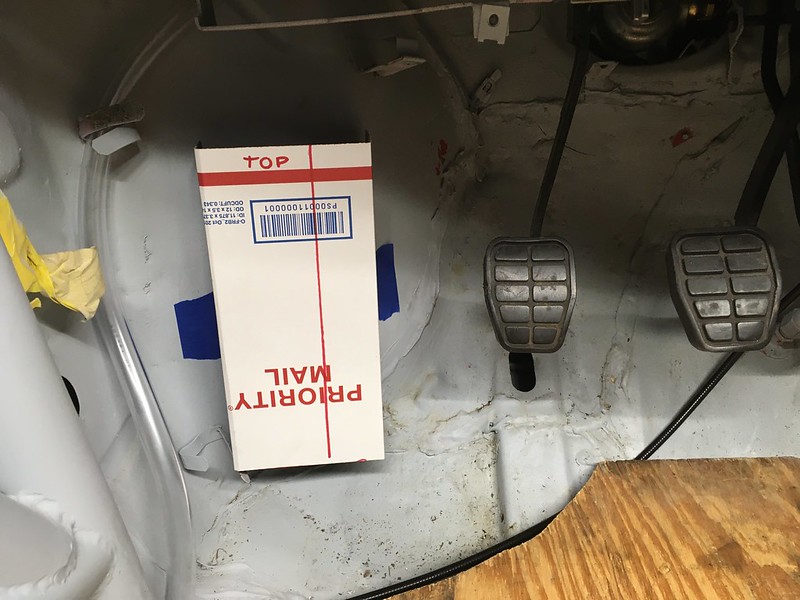
We may yet find something from Rennline’s catalog that’s fits the bill. For instance, this is our Rennline 911 footrest. Pretty close, eh?
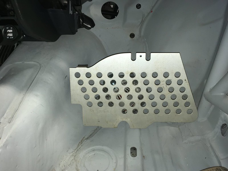
Regardless, we’ll need a bracket. So we made a template:


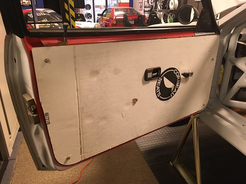
Creature comforts next. Door cards.
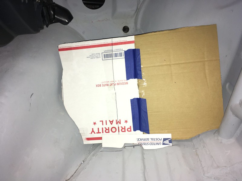
Unfortunately, there are no real precedents for door cards for a Group B Quattro as they used molded Kevlar doors that were essentially hollowed out. We’re not doing that. So, what to do? Fortunately, the stock Quattro door is pretty flat, apart from a small gap we made a patch panel for, so it looks like a flat panel of some sort will attach easily enough. We just have to come up with a shape, a material, some way to attach them and cut outs for door handles, window winders and door pulls. How hard could it be?
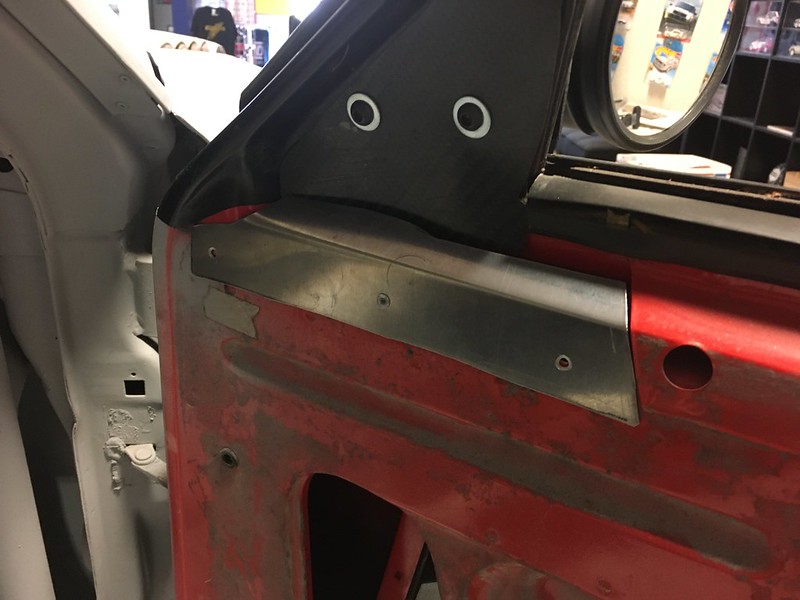
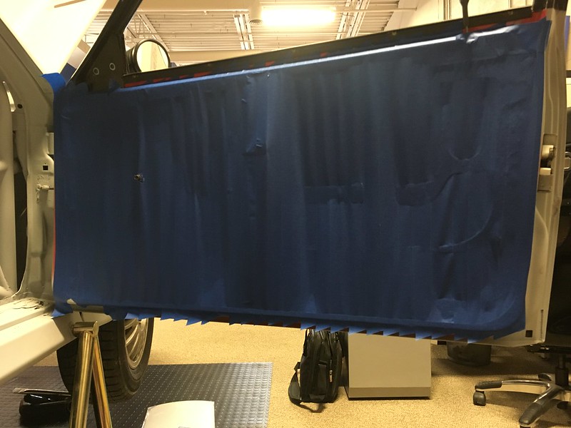
First we covered one door in masking tape. Then we drew around the periphery with a Sharpie and marked all the holes. Next, after a mug of proper tea and some Hobnobs to steady our nerves, we carefully peeled it off the door and stuck it onto a sheet of corrugated cardboard scavenged from a Corbeau seat box. Yep, same as our skid plate. Good stuff.
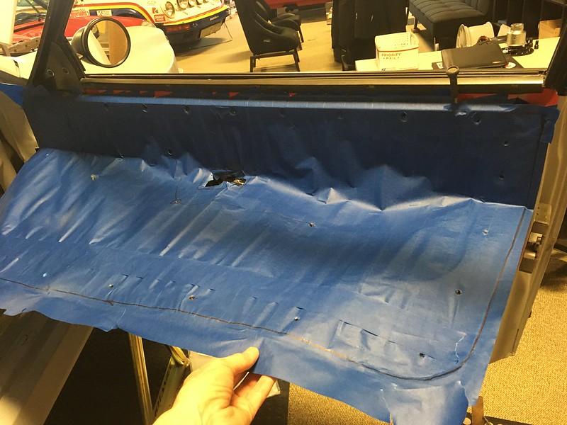
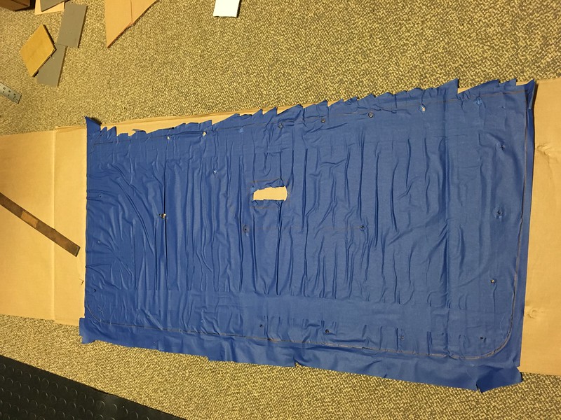
Then cut it out and cut it up.
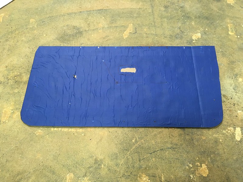
Surprisingly, it actually fit so we dug out the door handle bezels and temporary held it in place with some M8 bolts pushed into the original plastic fasteners that miraculously are still mostly present. Just needs some sort of door pull. We’ll get back to you on that.
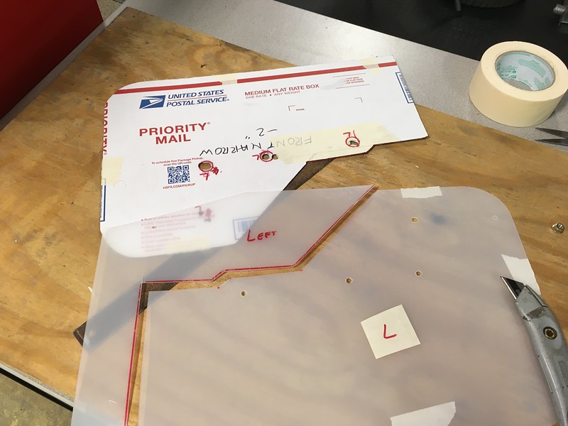
Now full of confidence with our auto-CAD prowess we decided to take on a much more challenging project: Mud flaps! You’re probably thinking “who welds on their mud flaps?”. Well, not us, but the ones on our role model had quite substantial brackets welded to the body and we thought we could mimic those pretty closely. Plus, brackets!
The fronts seemed the most straightforward so we started there. Break out the template gauge.

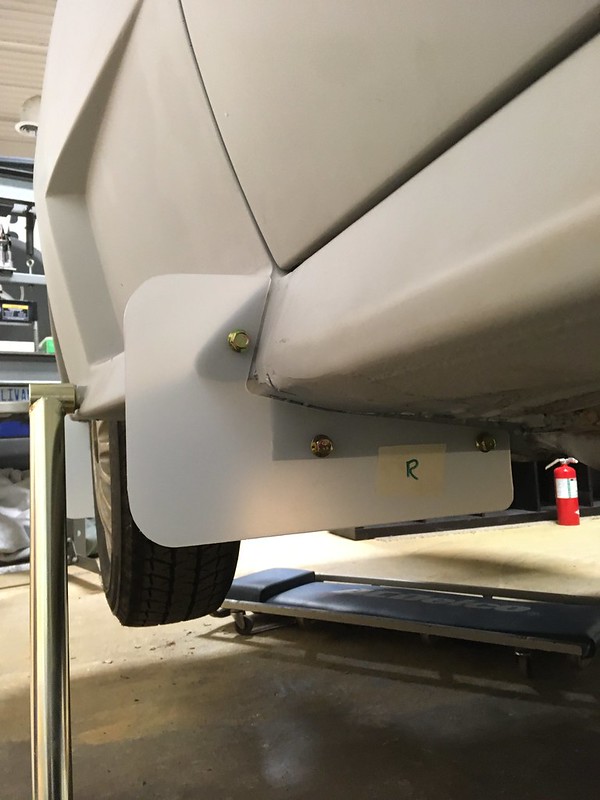
Fortunately, the car sits very level on its pin stands thanks to TRF, so we just used a small spirit level to make sure the bottom of the bracket is level and parallel to the ground. In our experience this is critically important with mud flaps as if they are even slightly off it will ruin the whole look of the car. Rally cars are principally mud flap display devices after all. OK, we may have lost the plot a bit but it makes us happy.

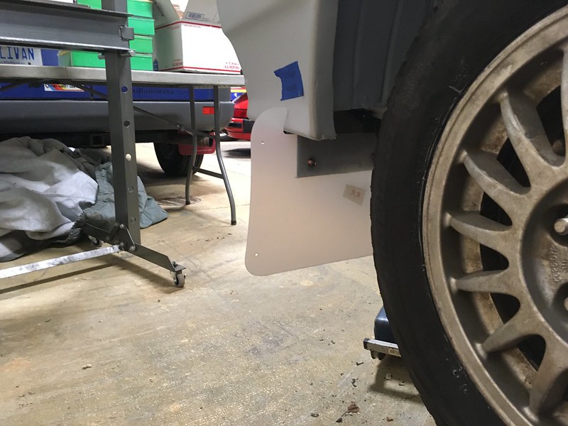
Now for the tricky bit; the rears. Still easy to keep level but, because they don’t line up with the end of the rocker panel like the fronts, a little harder to keep the same distance from the wheel arch and perpendicular to the centerline of the car. We tried though, really hard

A bit more profile gauge and scissor action and we had one side done. Unfortunately, both sides are not the same on the rear so we had twice as much work to do at this end of the car.
Bet you can’t wait to see what other auto cadding shenanigans we get up to next. And what about those door pulls?

Time For Proper Mud Flaps - With the mud flap brackets cadded, it was all we could do to resist cadding the mud flaps themselves. Actually, we couldn’t resist. Well, who could?
First, we started with something that isn’t present on the Group B resto we now seem to be trying to emulate in infinite detail: mid-rocker mud flaps (MRMFs), for want of a better term. What are those and why are you installing them? You may ask, Well, here’s an example that seems to only have been used on some of the David Sutton built cars in the UK.
It looks like it was used to mask a dodgy transition from the wide rear fenders to the rocker panel (sill in the UK). Well, that’s what we’re going to use ours for anyway as we have this going on due to, well, we’re not sure why. Maybe because we bought the cheap body kit.

Looks like it was almost designed for a mid-mud-flap (MMF?), don’t you think? So this is what we came up with. Of course, we also cadded a bracket for it. More welding required.

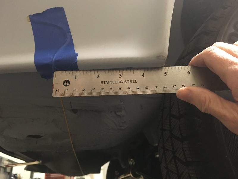
This gave us the confidence to tackle the proper mud flaps (PMFs). Incidentally, we think we are going to use Sparco mud flaps in white as they look to be about the same size as the works ones at about 11” x 19” (that’s 0.002 x 0.004 football fields in American units), are available in white, are cheap and thin enough to fit between the door and the front fender. We also use them on our rally 911 but in portrait orientation. On this car they will be in landscape orientation which is why we measure them in football fields. On the 911 they are 0.09x0.16 stories. We are not using aircraft carriers as a unit of measurement on this car; that would be ridiculous. First attempt seemed too wide.


So we lopped off 2”.

And are now much happier. They are now sitting about an inch inboard from the widest part of the fender (top) whereas before they were about an inch outboard. One could argue, on technical grounds, that they should be level with the widest part of the fender but we are happy with this result. Incidentally, it was quite difficult to get them lined up front to back. Like being level, we think it will be an important detail once the car is finished and took quite a bit of measuring and back and forth to achieve so we hope we are right.

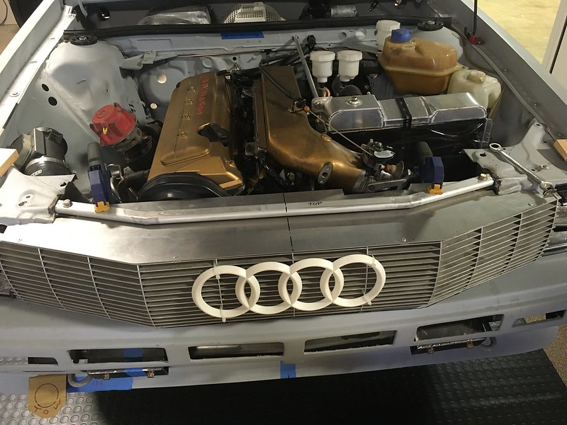
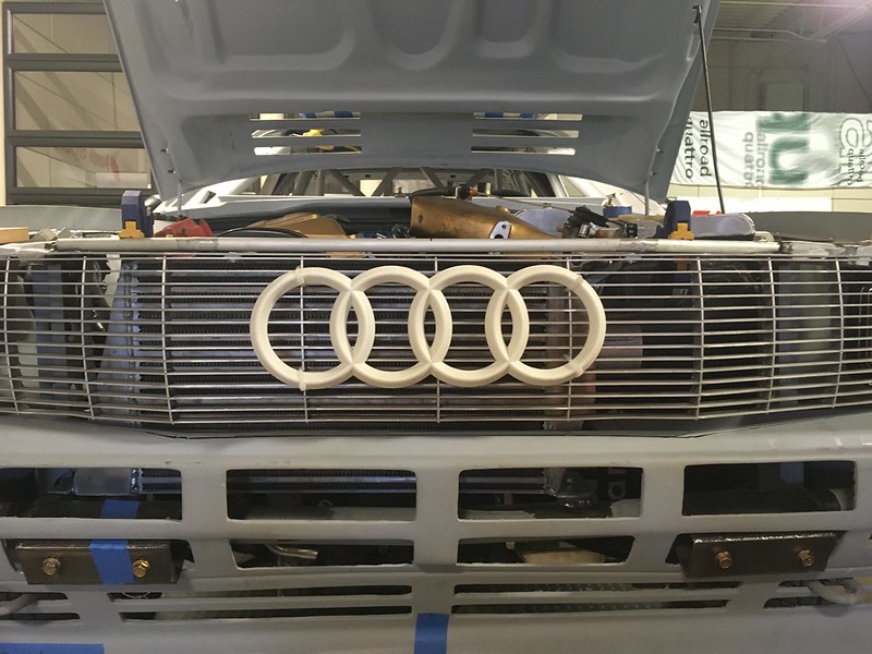
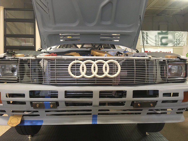
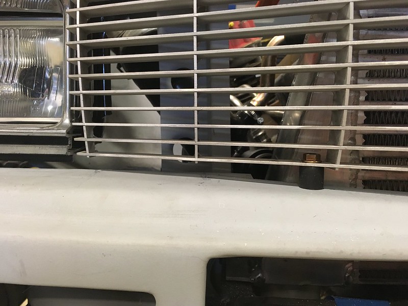
We took a break from cardboard engineering and decided it was time to grill, or attach the grill. This concoction of aluminium slats has been on and off the car for a while but, until now has never really been fully integrated into the front of the car. Sadly, we’ve just been wedging in in there and taking pictures of it. Ultimately it needs to be attached to the upper intercooler support in such a way that the two components can be removed as one. It also needs to be black eventually and we are thinking of having it anodized. Any thoughts on that? Also, part of this project is to attach the intercooler to the intercooler support bar. That way it will, er, support it.
The first thing to do was make it fit. Right now, the top plate is just wedged between the intercooler and the upper support bar but it didn’t go in far enough and was the wrong height. It also wasn’t parallel with the bumper, didn’t line up with headlight bezels and didn’t seem level! And we thought this would be simple.
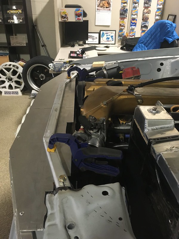
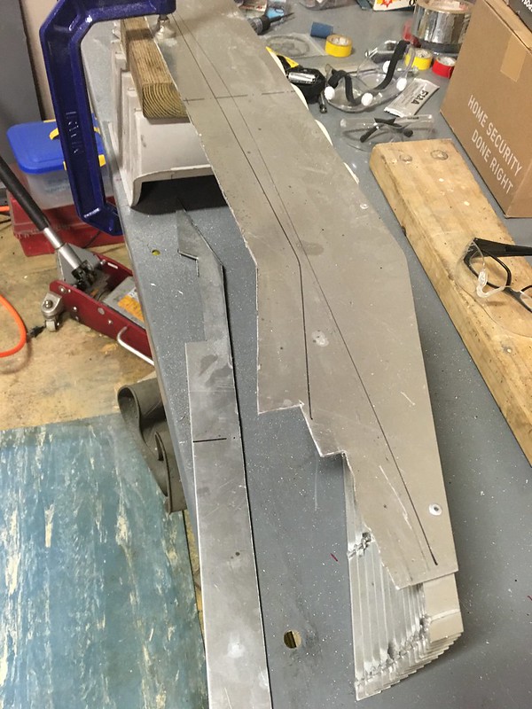
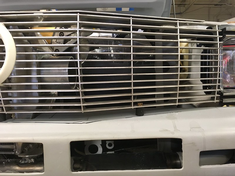
So, the first thing we did was remove some excess material from the back of the top plate.

And then clamped it to the upper support bar and asses what we had to play with. The bolt head will be to attach the intercooler later. Stop getting ahead of yourself.
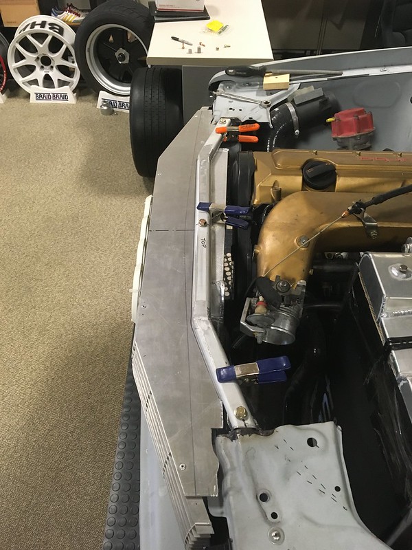
With a little bit of measuring, we determined that the bumper was level but a little warped and that the right side (left in the pics) headlight bezel was a little inboard. Otherwise, it looked good. We could have riveted the bar to the grill at this point but are not sure if we want the bar to also be anodized black so clamps will suffice for now. So how to fix the uneven bumper? We’ll tell you next time. (unless we fail)
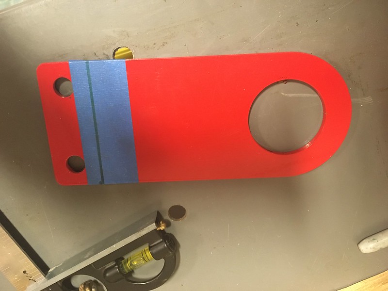
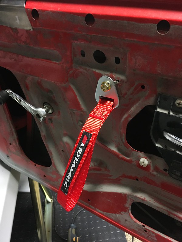
We're Hooked On Quattros
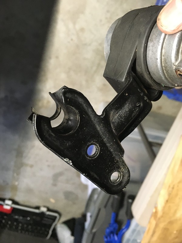
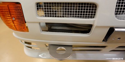
If you’ve been following this build, you’ll know by now that we have strongly resisted copying the works cars as much as possible. That is unless we can find an excuse to replicate what they did of course. So, it is with the front tow hook. Our car has perfectly good tow hooks that came from Audi. They work, we’ve used them to drag the car into the trailer more than once. They are a bit close to the bumper though and also make it harder to remove the bumper too as they protrude through it. They are also behind the lights when they are on. OK, they absolutely must go. Let’s see what the works cars used.

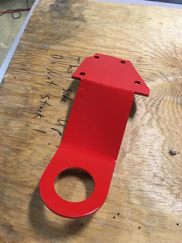
Yes, we can do that. How hard could it be? Plus, we have this shiny new tow hook from Rennline, that is too short and the wrong shape.
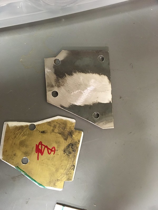
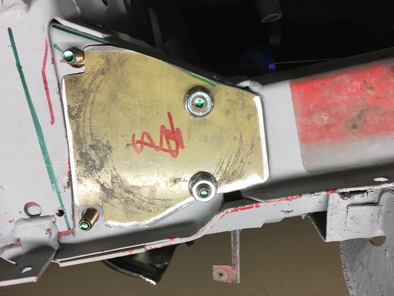
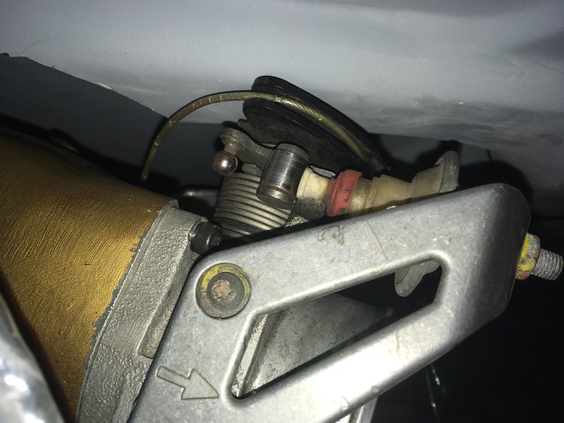
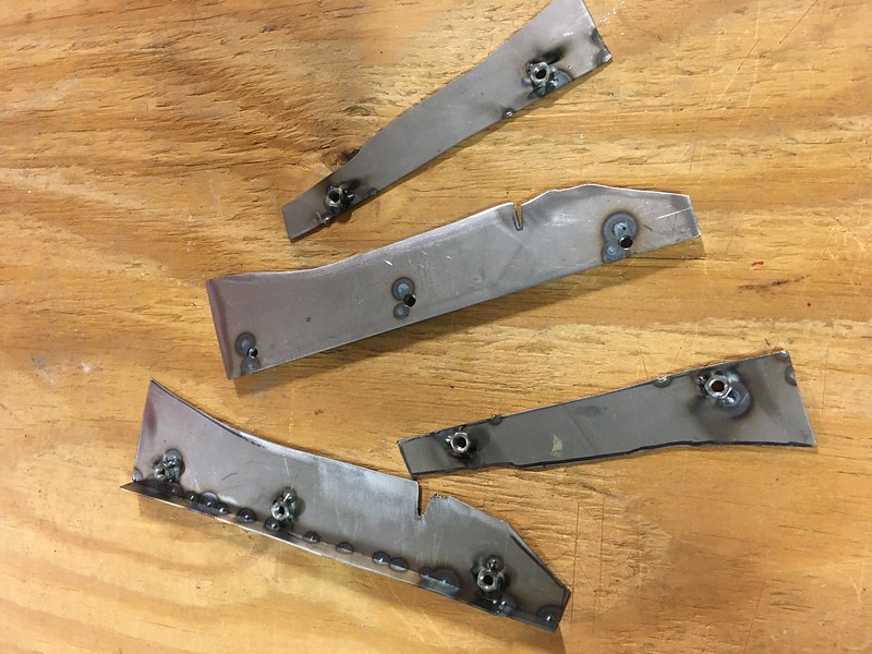
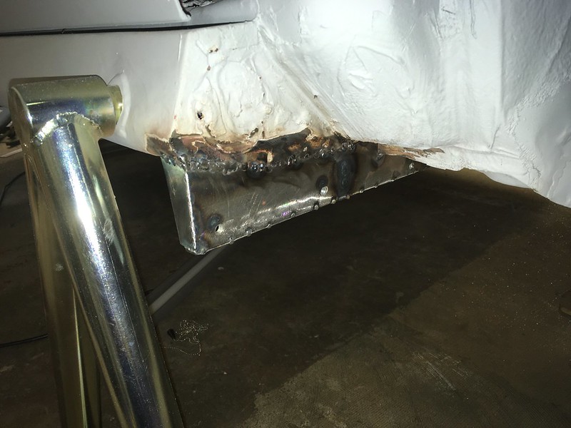
So, we bent it but it was still a bit short. We thought we could weld a 3/16” plate to it to make it longer and sandwich it between the chassis rail and the lower skid plate flange; just like the works cars. We made some nut (bolt) plates to help with this.

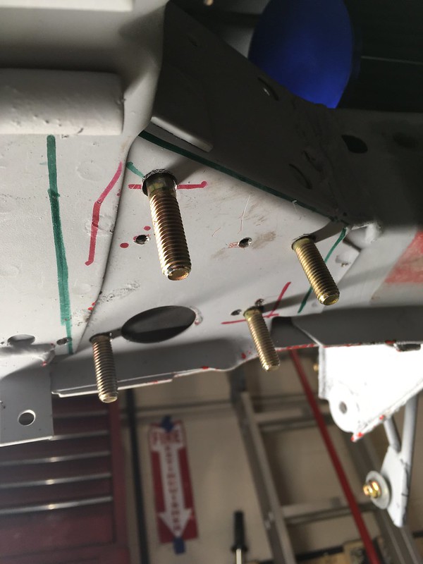
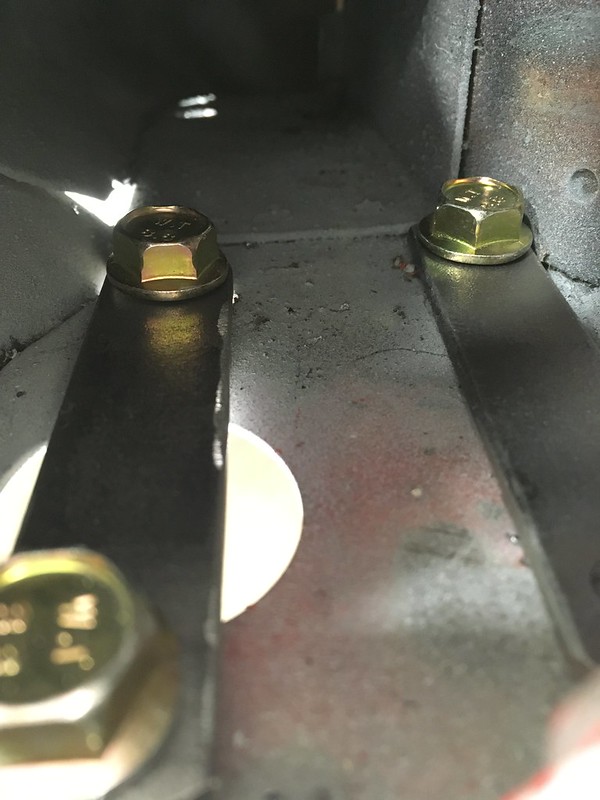
And some thin spacers to level off the underside of the chassis leg.
Then we made the extension for the tow hook and welded it on.

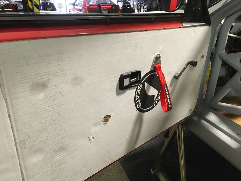
Of course, now we had our new, shiny tow hook we no longer needed the factory hooks so we got the grinder out.
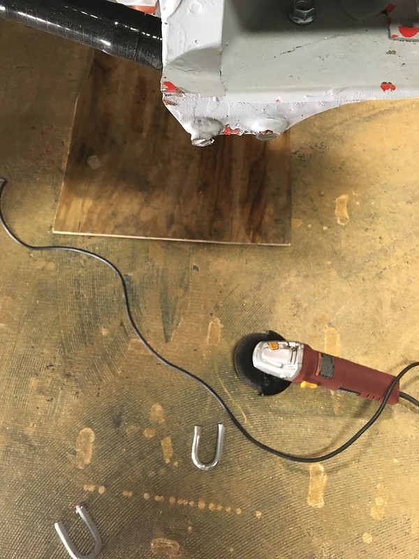

And then we were hooked.
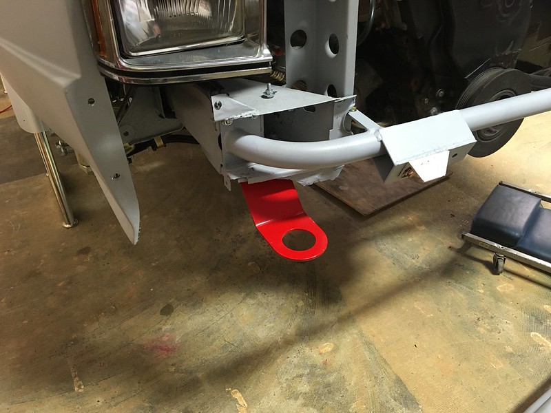


Yes, ours is red. So, therefore we didn’t replicate the works hook 
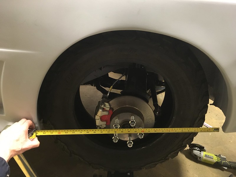
This week on "Will It Fit", we wanted to find out if a 215/65-15 BFG all-terrain tire would fit on a Quattro. Why? Because a customer wanted to know. Why? Because he put big-arse brakes on his quattro but now wants to go play in the dirt! We thought we could help especially as we had the exact same tire on our Allroad. Unfortunately we didn’t have any 16” wheels we could mount it on but we improvised.

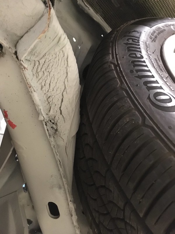
We were very curious because, you may remember, we had trouble fitting 275/40-17 Hosiers on the rear of ours. Not because of the width but because of the diameter which was only 25.7”. It seems the rear arches are very small so unless the chosen tire stays inside them they will impinge on the lip when travelling upwards. The BFG is 27”OD!
We’ve also seen that 205/65-15 rally tires (25”) will rub the underside of the spring perches but, fortunately, this customer’s car is already on coilovers.
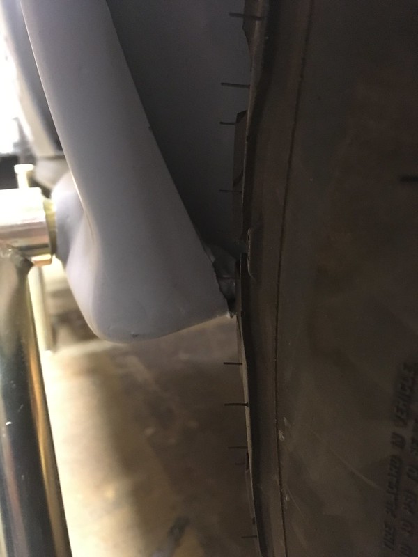
So, by balancing a tire on the jack we were able to determine that the BFG tire would just fit inside the arch lip and go up inside the wheel house, if the offset were selected appropriately. ~ET22
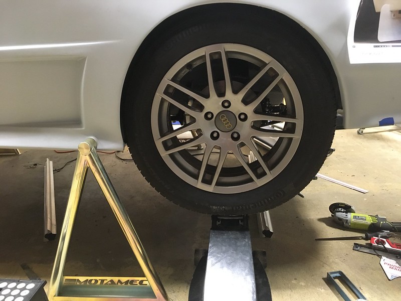
Then we remembered that our coffee table consists of four 225/55-17 (26.7”) tires on ET35 Allroad wheels and a glass top so we threw one of those on and it fit.
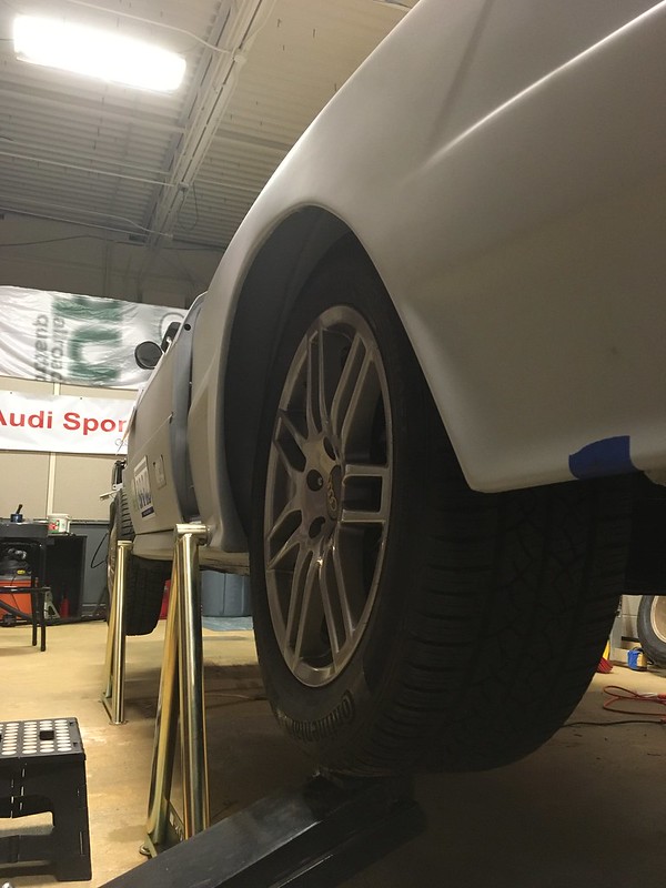
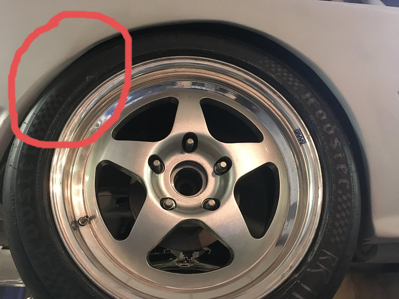
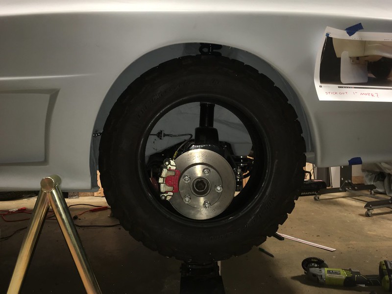
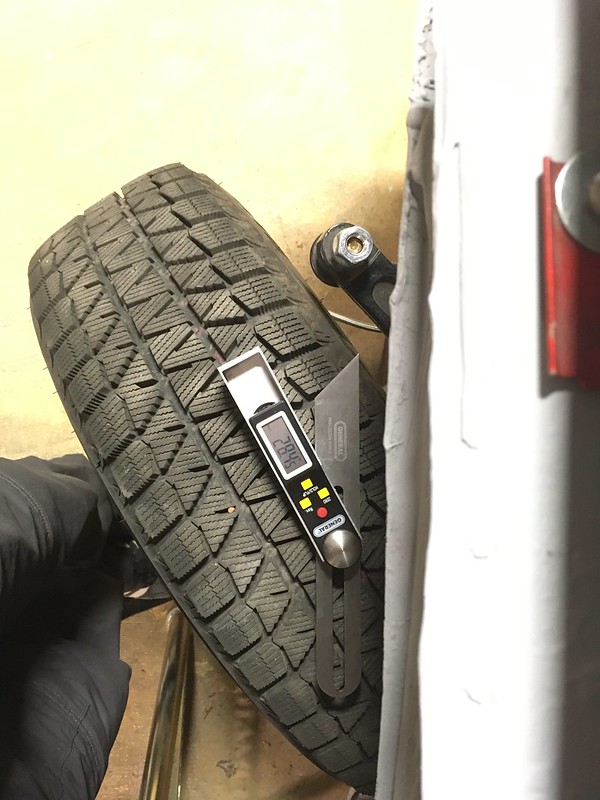
Then we tried it on the front:

Unfortunately this proved even tighter than the rear, for a couple of reasons. Firstly, it rubbed on the tie rod ball joint.

and front and rear inner fenders at full lock and full compression. Rears first.
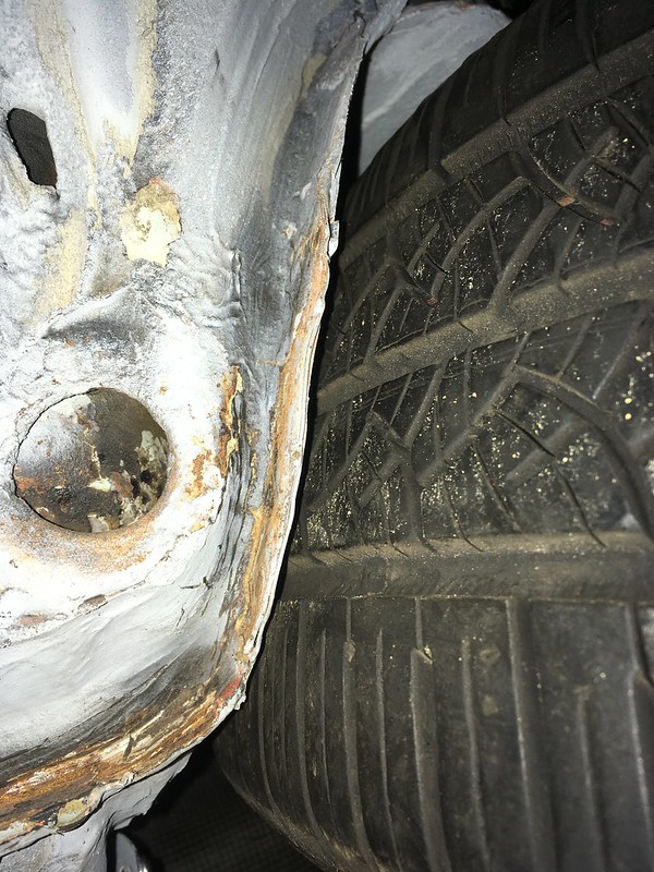
The ball joint is not a problem as this tire is 10mm wider than the AT tires being considered but it is also 8mm smaller diameter which means clearing the inner fenders is going to be impossible without hitting them with a BFH!
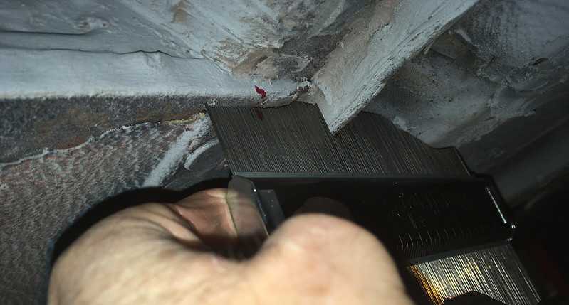
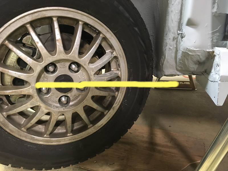
So what will fit? Turns out about 26.6” based on our jiggery-pokery.
Yes, that’s a 25” 195/65-15 tire with a socket being used as a feeler gauge! Not very big but do bear in mind the OE tires were only 23.5” OD. Still, all is not lost. Yokohama make their excellent Geolander A/T G015 in 215/60-16 and it is “only” 26.1” OD. So this tire might be an option.
https://ytc-bm.s3.us-east-2.amazonaws.c ... focal=none[/img]
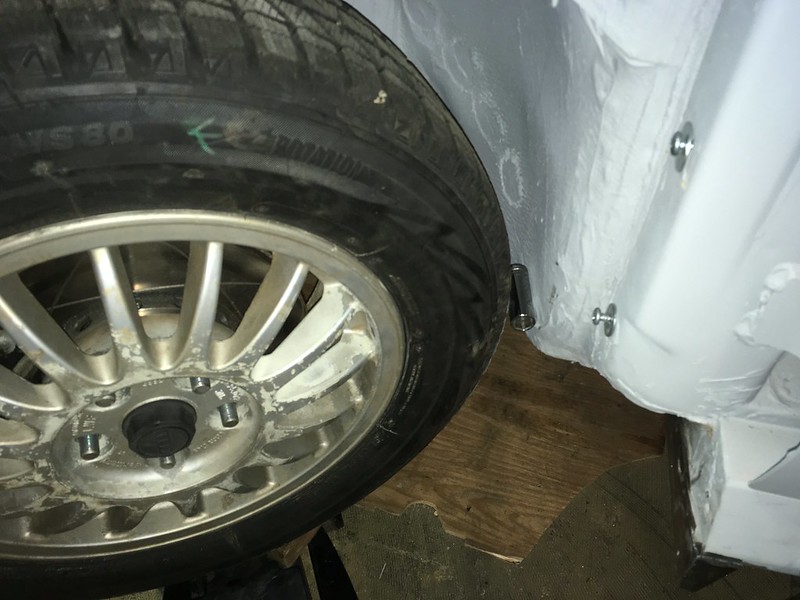
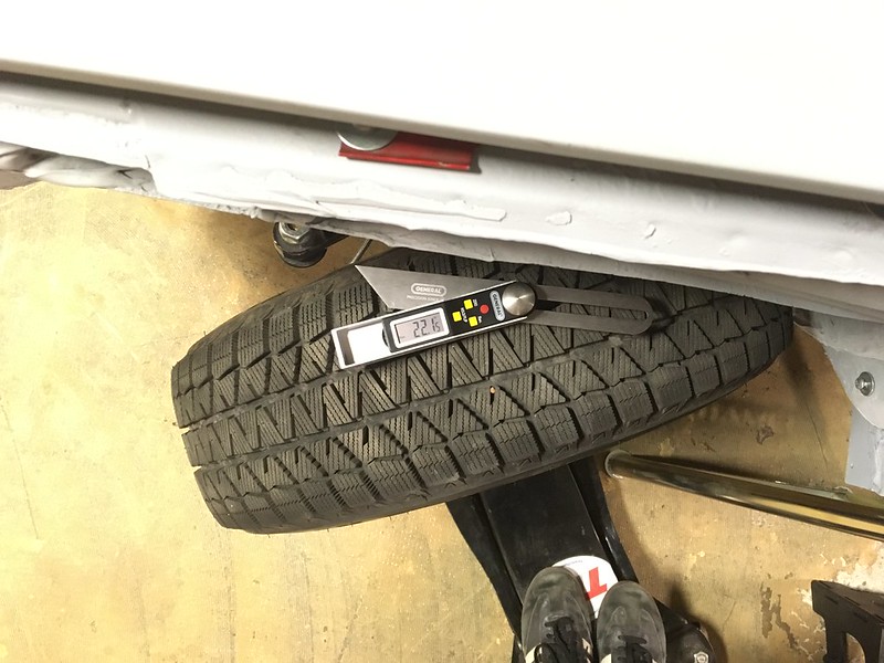
Still hopeful we could squeeze in the 215/65-16 we got creative. We investigated whether lifting the car would help. It is on coilovers after all. This is the 25” tire at full droop and, as you can see the center is about level with the bottom of the wheel house; the bit that rubs. So, unless you lift the car to the point that this is at full compression instead we don’t think a 27” tire will work.
Then we investigated if restricting the steering angle would help. With the small tire on we determined that full lock is about 28 degrees. Then, with the big tire on we found it doesn’t start to rub until about 22 degrees.
We are not sure if giving up 6 degrees of lock is a lot or how to restrict the rack but it might be a way forward. Alas, that is for someone else to figure out. We have a rally car to finish.
Time To Get In The Groove
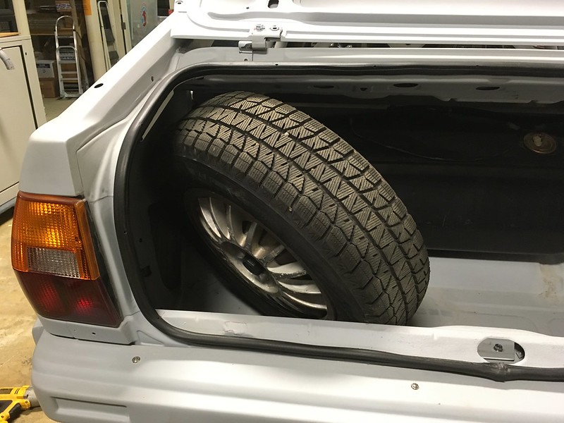
It recently occurred to us that if we ever get to drive this thing we might get a flat and need a spare tire. But what size and where to put it? The stock spare is a skinny donut that fits in the trunk up against the left quarter panel. Our car didn’t come with one and we doubt we’d wanna use a 35+ year old skinny tire anyway. No, we require something a bit more road worthy if not stage worthy.
This is also complicated by the fact that we will be running two very different sizes of tire on the car. 195/65-15 gravel rally tires and snow tires and 23/59-15 tarmac rally tires. While we don’t feel the need to carry an exact match we would like something at least a similar overall diameter. Unfortunately the gravel ties is 25” OD while the tarmac tire is only 23”! And we’ll need a suitable wheel.
There a lot of 195/60-15 tires on the market at 24.2” and a few 225/50-15 at 23.9” OD. Perhaps one of these would be the sweet spot. We also have a set of original 15x6 Quattro wheels we could mount one of these on. Well, the 195 anyway. 225 might be a stretch. Oh, did we mention, we’d also like to carry our emergency tool kit as well?
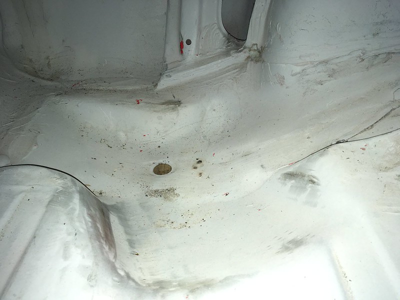
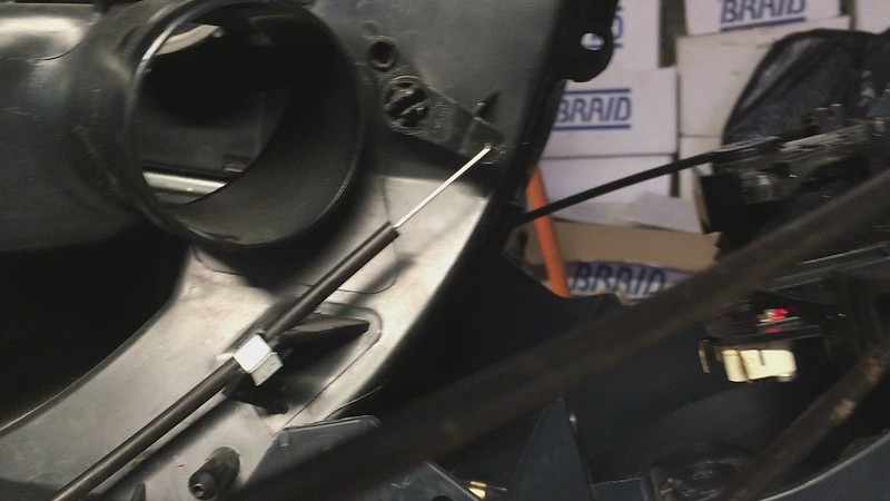
Now, where to store it. Well it turns out that nothing much bigger than the OE donut will fit in the original location so that’s out. However, since we removed the US spec bumper extensions from inside the truck we do now have access to this angled groove in the trunk floor. We thought it was to aid getting the donut into place but now we are thinking it may have been intended for a full size spare all along, at least till they got too wide for one.
Here’s a picture of the groove:
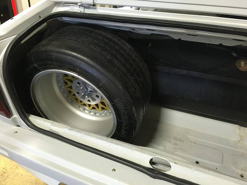
Let’s see what can get in the groove man! 215? Yes.
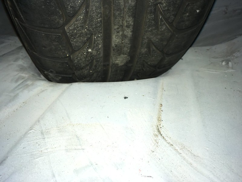
195/65 won’t fit in the spare’s location:
But will get in the groove dude:

225? Nah, not really but could be made to work:

195 and toolbox getting in the grove:
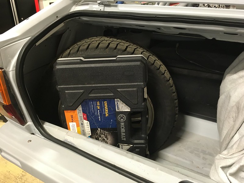
TB5 in the groove. Nah, don’t be silly. Fits in the trunk though, just:
So still not finalized and we’ll still have to figure out how to secure it. Now, back to more serious matters.
We’ve been frustrated by the rear muffler just hanging around but finally had some time to tackle it. We wanted to replicate the works cars even though it’s ridiculously over built.
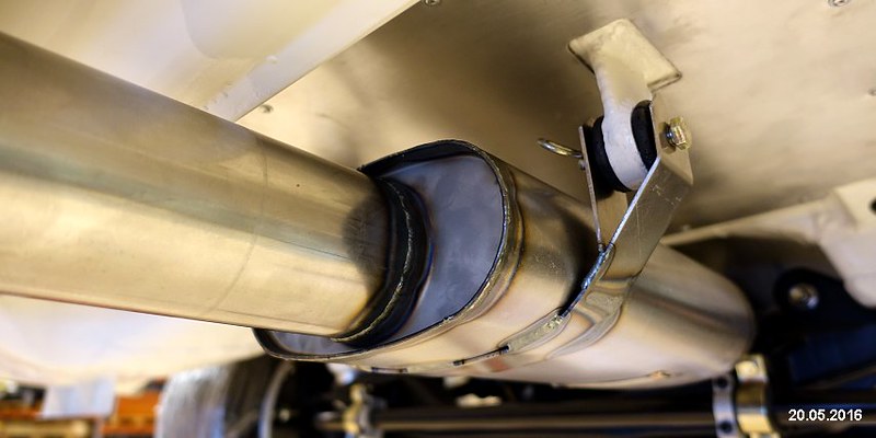
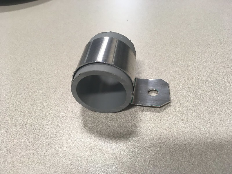
How hard could it be? First find some bushings from McMaster and some cardboard:

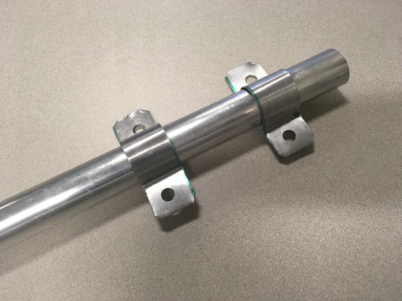
Guess the length and reproduce it in stainless:


Then weld it to the car:

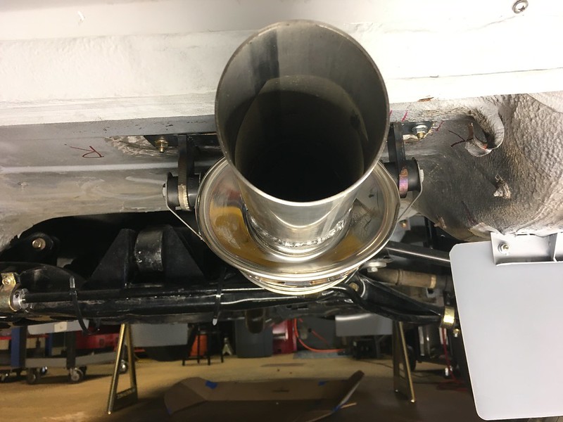
Actually, it’s screwed to the car for now. We’ll weld it once we get the car upside down.
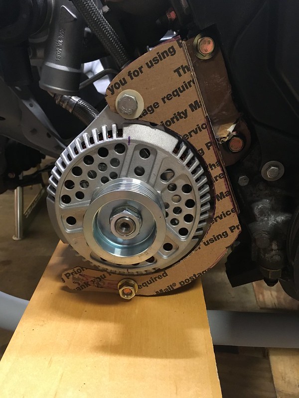
ALTERNATOR-TIVE UNIVERSE
We all know that Audis are different and UR Quattros even more different. Well, we also tend to do things differently and that did not change when it came to installing the alternator for our rally car.
We could have just used the stock alternator in the stock location on the stock bracket but that meant it wouldn’t be able to power our ridiculous number of lights, it would be right in front of the radiator and, after removing the power steering pump, be hanging on the end of a foot long appendage that just looked silly. So we said, “Let’s do something different”.
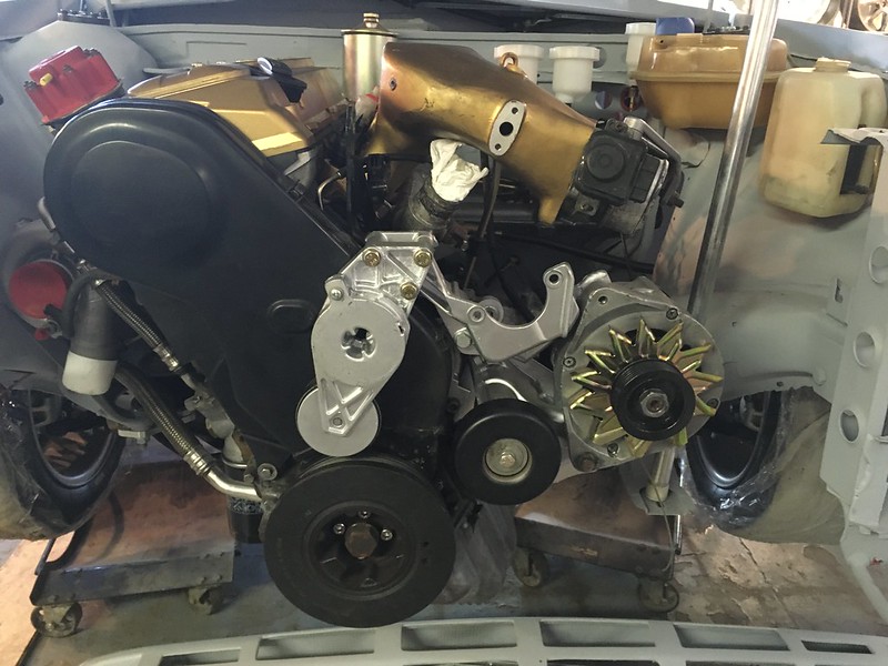
So we did two things. We found a relatively inexpensive 200 amp Ford alternator from a local supplier and we decided we could move the engine pitch stop to the left side of the engine. This meant we could mount the alternator on the right side of the engine with a custom bracket.
https://live.staticflickr.com/65535/...3147db6d_c.jpg
Now some of you are probably saying, ”Why didn’t you just use a bracket from an Audi that had the alternator on the right side of the engine?” Well, we could do that but Audi didn’t use Ford alternators did they? Custom bracket it was then. How do you do that? You might ask. So did we!
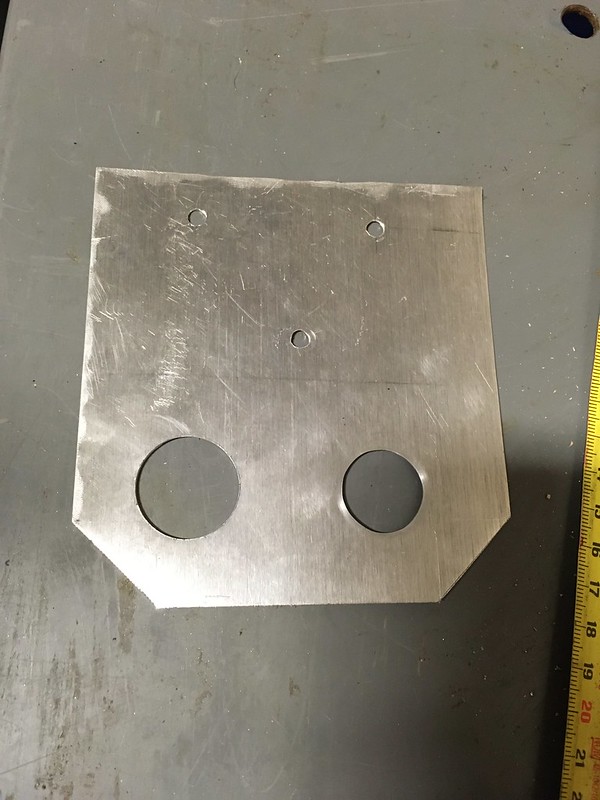
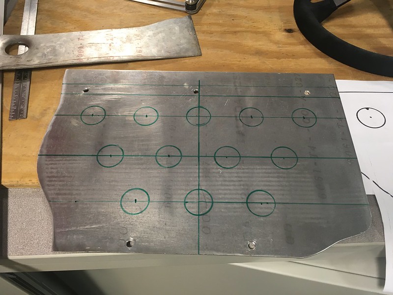
We started with a CAD template, of course.

Which we cunningly fashioned into a front bracket looking thingy.
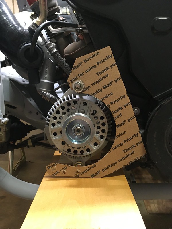
Then we made a base plate that would bolt to some existing holes on the block

Then taped the two together
Once we were happy with the design, we cut the pieces out of 3/16” and 1/8” steel plate.

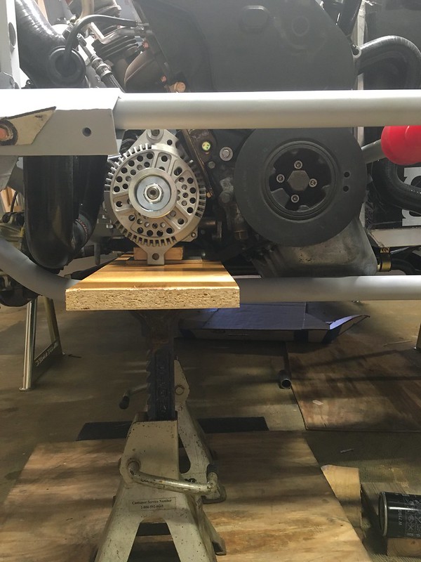
In order to ensure (hopefully) that the two pullies were lined up in every conceivable axis we decided to clamp them together using a very stiff piece of angle iron before welding everything up. This seemed to work, much to our surprise. And yes, we checked, with measury things.


Then came the tricky bit: Finding a belt the right length.

Piece of cake (actually, we prefer Hobnobs thank you)


