


Can somebody point me to a drawing for the transmission bolt pattern for a 1.6l Ford Ecoboost? I believe this should be the same as for a Ford Sigma or Zetec SE.

Can somebody point me to a drawing for the transmission bolt pattern for a 1.6l Ford Ecoboost? I believe this should be the same as for a Ford Sigma or Zetec SE.

Anyone still following this thread?
Im in need of a little help. I recently was given an old whisper chipper with a bad motor. I was told the motor in it was a 4 cyl ford ranger motor.
I know these chippers also came with the ford 300 I6. My question is are the 300 bolt pattern and 2.3L pattern the same?
The 300 is a little easier to find and the upgrade would be nice too.
thanks in advance
Deviater
Just found info on another site that the 300 uses a smallblock pattern so I'm guessing my answer should be that the bolt patterns are different

In reply to Deviater :
I know sbf and some Ford i6 shared a bellhousing pattern but the 2.3 Lima is a different animal afaik. Should be easy to find a replacement 2.3 just about anywhere for super cheap. Definitely more of them out in the wild than 300s left.

Back to the GM metric pattern vs the Ecotec. Credit to fieroguru on some obscure Fiero forum.
The Ecotec and Metric bellhousing dowels are indeed in the same location... but there are a couple of reasons most don't believe it.
First whenever you are looking at the pictures with dimensions, you have to determine if you are looking at the engine view or transmission view. They will be mirror images of each other.
Here is the transmission view of the GM Metric Pattern:
Here is the engine view of the Ecotec Pattern:
Second, when looking at the dimensions between these two drawings, don't assume they don't match because they have different X-Y dimensions from the crankshaft. If you lay out the dimensions of the dowel pins in autoCAD and rotate the transmission 6.82 degrees clockwise then they do match up.
So Yes, you can align the Ecotec engine to the GM Metric transmission by using the dowel pins... but will result in the engine and transmission being rotated from each other by 6.82 degrees.
However, none of the other bolt holes will line up. You may be able to located them and just re-drill the transmission bell housing or make a simple adapter plate for the bolt holes (doesn't need to be precise as the dowels will provide proper alignment

I have no bolt patter because you don't need one for this. Did you know that the Toyota 2GR FWD engine block will bolt up to the E153 manual transaxle from the MR2. V6 mid-engine that's mostly just a bolt together. There's one hole in the block that is already there that needs to have a Helicoil installed. Not every bolt hole ends up with a bolt but there are enough to keep it all together.
The flywheel from the 1MZ/3MZ V6 fits the 2GR crank and is the correct diameter for the starter. Fidanza makes an AL one too. The clutch disc and pressure plate from the turbo MR2 bolts up the 1MZ flywheel and there's a ton of options there. The MR2 Turbo has the option of an LSD diff too.

 In reply to Flight Service :
Drawings? Why do things the hard way? Take the engine and transfer the holes. Then take the transmission and transfer those holes. Grab a way to measure the depth and you're good to go. It will take you a morning.

In reply to frenchyd :
That adapter is Jaguar V12 to ...?
In reply to frenchyd :
Ask Dusterdb13 about how thousands of inches can cost you thousands of dollars.
In reply to Stampie (FS) :
That's exactly why you use the actual pieces instead of drawings. Drawings are scaled down versions with the potential for error. With the actual pieces on hand, errors become that of sloppiness or carelessness.
With drawings while in addition to those chances of error, there is the potential of interpretation errors, perception errors, measurement errors, etc.

In reply to frenchyd :
As someone with an engineering background, you have funny ideas about drawings.

Scott_H said:I have no bolt patter because you don't need one for this. Did you know that the Toyota 2GR FWD engine block will bolt up to the E153 manual transaxle from the MR2. V6 mid-engine that's mostly just a bolt together. There's one hole in the block that is already there that needs to have a Helicoil installed. Not every bolt hole ends up with a bolt but there are enough to keep it all together.
The flywheel from the 1MZ/3MZ V6 fits the 2GR crank and is the correct diameter for the starter. Fidanza makes an AL one too. The clutch disc and pressure plate from the turbo MR2 bolts up the 1MZ flywheel and there's a ton of options there. The MR2 Turbo has the option of an LSD diff too.
Paging maschinenbau....

Most CAD software can convert files to different types. With a 3D step file or native cad you can make a print then make a PDF of it for all to see.
I can help if you only have a CAD file and want it translated.
This is the best way to make an adapter plate, overlay the two files, blow holes through and send it to the CNC or manual mill. Every thing is accurate down to the capability of the machine, usually tenths. .0001
Clearly this works the other way also, start with bolt pattern prints, develop a model then cut it. I made some stupid bolt patters adapters this way.
Mr_Asa said:In reply to frenchyd :
As someone with an engineering background, you have funny ideas about drawings.
I've seen some sloppy work done off drawings. In fact a lot of v12's converted to manual transmissions were ruined because of a mistake someplace. Basically what happened is the transmission was shoved too far forward and quickly wore the thrust bearing through and then the crankshaft started grinding away at the block.
One of our own GRMers had that happen to him. Plus several had it happen to their V12's on Jaguar web sites.
With pieces on hand that's too easy to catch.
If you think it doesn't happen with engineers and proper drawings you haven't talked to them. Well, I suppose it's hard for a professional to come right out and say, "I made a mistake"
Maybe with a Modern mill, and proper tooling etc. the finished result will be nicer. And accurate.
But you're paying for all that cost.
For me the only cost involved is what ever the cost of surplus aluminum is.
To be fair I learned how to do this when Jack Baker had to adapt a Holman and Moody 427 Ford engine to a Hewland gearbox. While Jack was an engineer, the time to do an accurate drawing would have been massively more than it took him to hold a piece of cardboard up and trace around it.
For me, I even skip the cardboard and clamp a piece of Aluminum to each. Then using proper sized drifts center punch each hole.
It's maybe a few hours work from clearing the workbench to putting away the tools and scrap aluminum. How much time do drawings take and scheduling a machinist to do the work?
In reply to frenchyd :
I'm both the designer and machinist, and I still don't have the time for cardboard templates. I frequently make cad models for even simple designs or fabrications because I will usually catch mistakes as lines vs chips. Beyond that adding thoughtful details usually happens once I stare at a design long enough.
Once you get proficient with a CAD program it is very fast to make and measure models. Add a 3D scanner and you can recreate anything quickly and accurately, I have only watched, this never done it myself.
Nothing wrong with the cardboard method but in my world most of what I make needs to go into the vault so ten years later someone can recreate it from the model and print.
You have skills that most will never learn, there are less people interested in learning those skills every year.
How do you find the centerline of mismatched components? I understand spotting the hole patterns, how do you quickly determine exact bolt pattern to centerline of crank or input shaft? My biggest concern in concentricity of the shafts.
Yes, finding the centers is the hardest part IMHO.
I'm making a RWD Honda L15B7 with a BWW Getrag 260 transmission.
Both motor and trans each use two precision hollow bushings to assure shaft alignment.
So that gives 3 critical alignment points on each side, the bolt holes could be done with transfer punches.
I could use dykem, dividers, scribes, punches, and Jr High Geometry to try to precisely determine the centers.
But laser scanning can easily resolve to under 0.001", according to metrologists I've talked to.
Plan is to scan the mating faces of each, convert to STEP files, align the axes, and rotate just far enough to avoid any bolt/bushing collisions.
CNC fabricate the result.
Fortunately, the clutch disk on both is 230mm, and the BMW pilot shaft tip is smaller than the L15 pilot bushing OD,
so a simple bronze bushing can adapt, the plunge distance and spline position will determine the adaptor plate thickness.
Unless someone has the L15 and BMW patterns handy ... anyone willing to share?
Anyone got an Aussie Valiant Hemi 265 bellhousing or Borg Warner 4-speed single rail pattern?
In reply to akylekoz :
Valid question regarding location of the locating dowels. Used for finding the crankshaft Centerline.
In the case of the Jaguar V12 & Chevy mashup. Jaguar used the Chevy location for dowels after 3/4 of 1977.
Prior to that I used a bare block, an empty transmission case and alignment shaft. I'd zip up some pucks on the lathe and Bob's your Uncle.
Since not everyone is fluent in Cad design my method provides tens of thousands more with the ability to swap tranny's.
Frankly I suspect it's a dying art. Either way. EV's don't need Transmissions. And that's the way the world is headed.

Hard to screw up alignment when using an alignment shaft.
I made my own bellhousing to adapt a Ford Toploader 4spd transmission to my old school SB Chev V8. I wasn't concerned about it not being "SFI certified", as it's just a fun street car.
The mock-up began with an empty block and transmission case. I used the alignment bar from my rearend narrowing jig to keep everything straight and true. I machined some steel pucks to fit in the block's main bearing bores and also the bearing bores in the transmission case. The pucks have an 1.501" hole in the center so that my alignment bar will slide inside everything to keep the engine and transmission bores concentric. I made a ring to center the plate that the transmission will bolt to, and a tube spacer that will set the desired distance between the block and transmission face. I also made the rear plate that the transmission bolts to, and laid out the the flange that bolts to the block and serve as a pattern for the block plate that will fit behind the flywheel. Most parts were plasma cut by hand, then flap wheeled to the scribed profile.
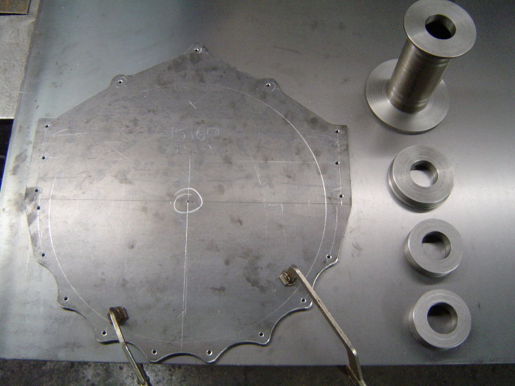
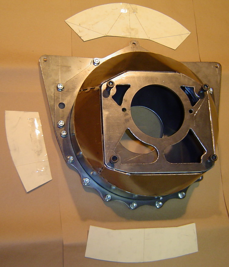
Here's the pattern I made out of 1/4" steel. All the hole locations were laid out, centerpunched, and drilled 3/16" so that the pattern could be transferred to the blank piece of 1/8" that it's laying on, which was used to make the block protection plate. The steel pucks on the right are the pilot rings for the alignment bar which made sure the block and transmission centerlines are concentric. The tall depth spacer is actually 3 pcs. The lower sits against the face of the block, the upper sits against the front face of the transmission, the center is a 2-1/2" x .065" tube. Length of the center tube sets the distance between the back of the block and the face of the transmission. Later this pattern got it's bolt holes drilled and the large center hole was cut out, the pattern became the flange for the front of the bell...
Here's the drawing I used to lay out the block bolt pattern...

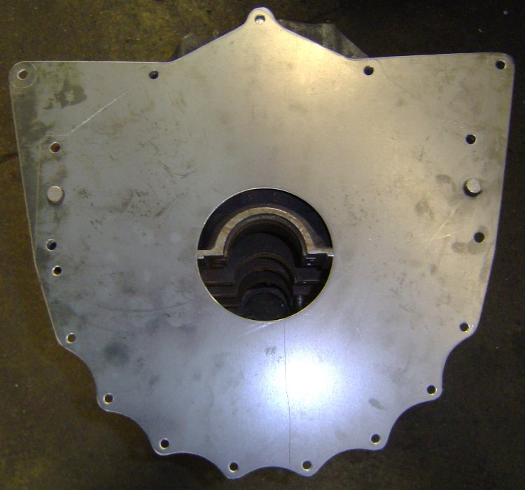
This is the block plate after it was cut out and drilled. The large hole in the center is for the crank's flywheel flange to stick thru, and the 2 larger holes on the sides are for the locating dowels in the block...

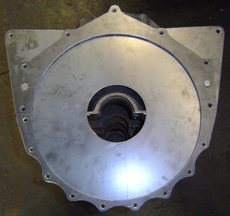
This is the pattern after i drilled it out and cut the center out. It is going to be the forward flange of the bellhousing that bolts to the block, the large hole in the center is necessary to clear the flywheel...

Here's the block plate on a block. The upper "wings" were added as mid-mounting points that will hang the back of the engine at the firewall...
Here's the block plate and flange on a block. The block plate will be sandwiched between the block and bellhousing as shown.
Here's a pic of the rolled ring welded to the bellflange. All the holes still fit perfectly...

The mid-mounts incorporated into the block plate allow me to easily remove the bellhousing/clutch/flywheel from the car without needing to support the engine. Greatly simplifies my clutch and transmission maintenance.
Here's the alignment bar in place in the block, as well as the spacer that sets the depth between the block and trans case...
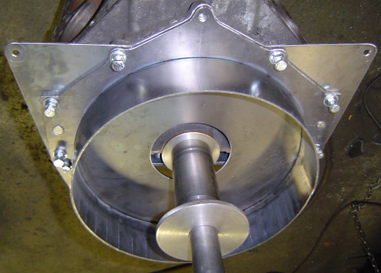
Here's the trans case in position located by the pilot rings...

I started making patterns for closing in the bell by laying out the the top section on posterboard. I quickly realized it was much easier to just cut out slightly larger pieces of posterboard, hold them in place on the bell, and simply apply a little pressure by running my finger around the edges of the steel. This puts a small crease in the posterboard and transfers the exact shape needed, a much quicker way to create a pattern...
In this pic the transmission plate was still only tacked in 4 places. After all the rest of the welding was done, I put the bell back into the fixture, cut the tacks, and re-positioned the plate for the best alignment possible before welding it in place. Doing it this way there is no need to machine the block or transmission mating surfaces of the bell.


Added a cutout for the mini-starter's drive...

Added a starter pocket to the bell as well...
At this point all the welding was finished up, with the exception of the transmission plate. The last part of the welding process is cutting the tacks that hold the trans plate in place, then re-installing the bell on the alignment fixture to ensure proper alignment before welding the trans plate to the rest of the bell. Also added a few holes, one for setting the clutch gap and a hole for the hyd t-brg's hose.
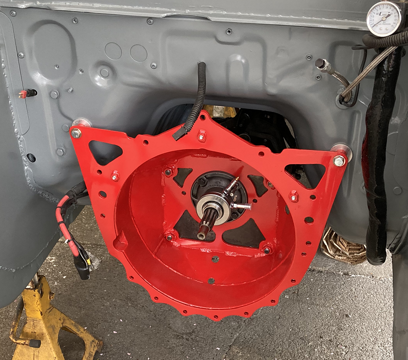
Here's the finished product...


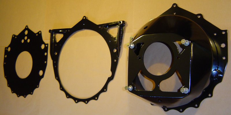
I ended up going to a 3pc style bellhousing...blockplate, midplate, bell. This allows me to remove the engine from the car with the flywheel and clutch, and leave the bell and transmission mounted in the car. I can also remove the transmission/bell/clutch/flywheel from the car without supporting the rear of the engine. I also added a couple external "ears" to the block plate, which gives me some easy attachment points for lifting the engine.
The finished bellhousing itself weighs in at 16.3lbs. The Mcleod aluminum/titanuim bell is only 1.5 lbs lighter!!! The entire 3pc assembly shown below, including the block plate, midplate, and bolts, weighs 26.2lbs.
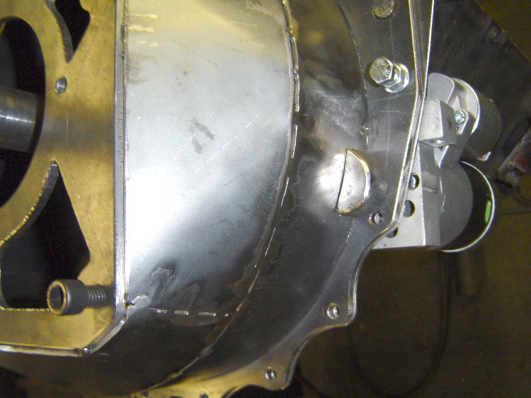
Here's a pic of how/where the midplate's "ears" attach to the RX-7's relocated firewall. In this pic you can also see three nuts that were welded to the midplate, those three bolts were added to keep the bell attached to the midplate when the engine is removed...
This shot from the inside shows one of the aluminum firewall reinforcements installed behind the firewall. They serve to spread the load over a wider area so that stress transferred from the midplate does not buckle the thin stock firewall's sheetmetal...
Grant

This thread is the most fascinating one I've seen in some time - both in concept and content. It's a subject of interest to me, but highlights my shortcomings in both CAD and machining. I've managed brake conversions with templates, eMachineShop and hand tools, but driveline, as mentioned, is a much more exacting science. Thanks to all the contributors.

 Ford T5
I was searching GRM site for scale plans and found this one.
Wow. Don't know how I missed this one when it was first out, but saying that bell housing is impressive is a huge disservice.
Thats not just metal fabrication, thats structural art. 100% blown away...

Does anyone have a drawing for the Mazda MZR L motors? Same as Duratec I think.
I have a transaxle but no way to accurately find center.

Stampie said:
Audi 4 cylinder pattern
Not quite. That is a combination of the 4 and 5 cylinder patterns. Audi made single pattern transmissions before 1989 or so, then dual pattern afterwards, so the same trans could bolt to a four or a 5/6/8 cylinder.
The four pattern is literally four bolts. The five pattern has seven. The starter bolts to the trans on a four, bolts to the engine on a five, with the bolts being throughbolts to the trans case.
![]()
Of course, the 07K five cylinder uses the four cylinder pattern, and VWAG never made a transverse trans for the 5/6/8 pattern (except maybe some rare Eurovans that angled the engine weirdly) There are also at least two different dowel pin diameters for the five pattern.
Further edit: just to add confusion, the Audi 5cyl pattern started life as the pattern for the old pushrod four that eventually became the Porsche 924 engine. VR6 and W8 engines are different and are not part of "5/6/8".
Because it's needed. Thanks Kieth.

You'll need to log in to post.


