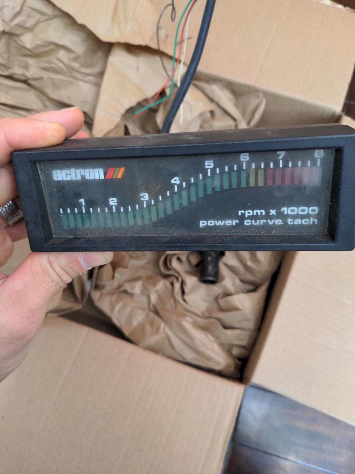
So I got an old LED bar style tach recently along with some other fiat parts. I think it is sweet, unfortunately, on the backlights work. No taching.
It seems like the board is actually big enough for me to replace parts, and I thought I might try. What's the general process? Nothing looks obviously wrong, no caps exploded, nothing burned, etc.
Do I just start testing capacitors and resistors to make sure they match their stated values? What next?
of no help to fix but it brings back memories of day dreaming flipping through the old jcwhitney catalogs
Documentation is key. A lot of this stuff has some "mystery components" that can be impossible to figure out... and may be made of unobtanium.
Pretty sure that there are some old DIY oxygen sensor gauge how-tos out there that detail how to do circuits for this sort of thing. those turn voltage into a bar graph, but there are also circuits to turn frequency into voltage...
If nothing else, it may make what is going on in the circuit board make sense.

Mr_Asa
UltimaDork
10/5/22 1:52 p.m.
Post up model numbers and such, maybe someone has better google-fu abilities than you do.
Is it actually not doing anything, or are the inputs not correct?
Likely an old IC gave up the ghost. Agreed on posting any PN that you can read and some pics of the board.
Thinking the connections are 12v, gnd, tach and dimmer/lights?
I might even have what you need sitting at my work that's been collecting dust for the past 20+ years
Heres the board:
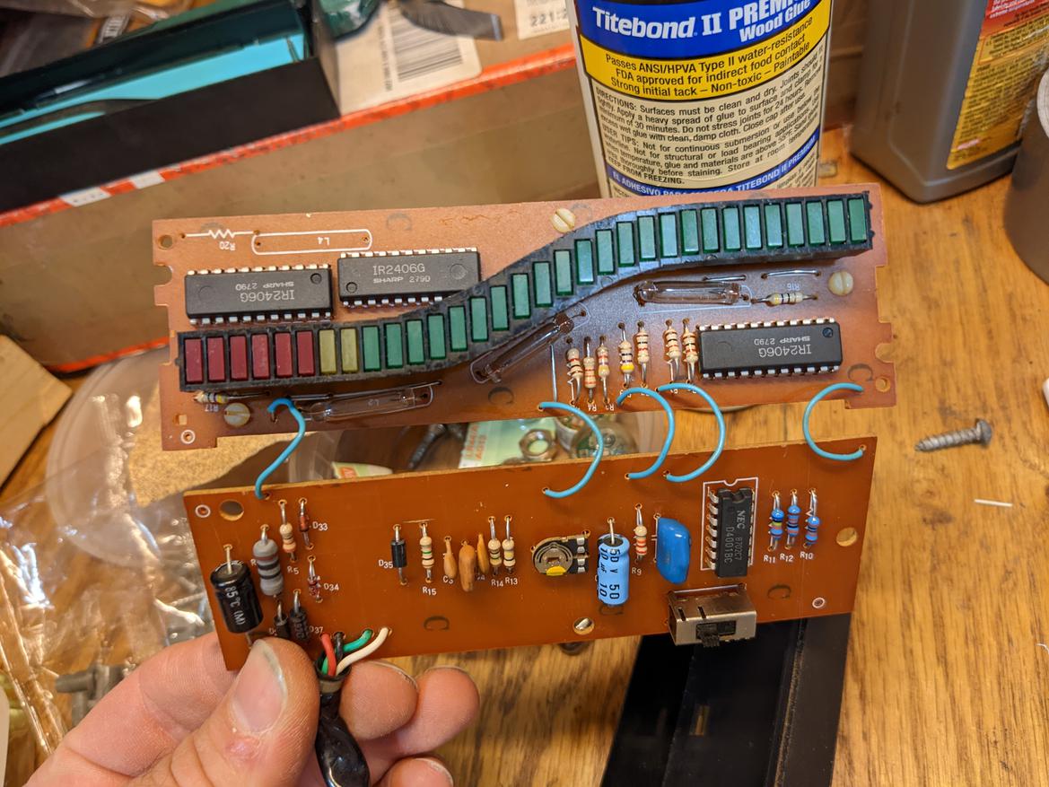
Looks like relatively simple logic gate chip and then 3 controllers for the LED panels. I can find data sheets for both on the internet, it appears.

I also found this loose connection, and fixed it. It did not seem to solve the problem.
As far as hookup, I'm pretty sure it is black - ground, red - 12v, white - dimmer (12v or less) and green - tach. I guess I could be wrong.
The switch is for 4, 6, or 8 cylinders. It seems to work. The caps all had capacitance similar to their marked rating. Didn't start testing resistors.
How do you test diodes? I was seeing weird resistance values on my dmm in both directions. Maybe there's supposed to be a diode mode?
This is fun!
I found a Fluke article on testing diodes (sounds like diode mode is better, but can do some testing without).

Noddaz
PowerDork
10/7/22 6:55 p.m.
That is really kool! You need to fix that!
I probably know less about electronics repair than you do, but so far all the early 90's honda stuff I've worked on has been fixed by replacing all electrolytic caps and re-flowing the solder connections.
Beyond that it should be easy to test the switch, the LEDs and that potentiometer(?) in the center. It's definitely possible that an IC died, but it's been rare in my experience.
So, I made an educated guess about the way this thing works. I postulated that the 4001 chip was probably turning the tach signal from frequency to voltage, and then the 3 2406 chips we're taking the voltage input and driving the LEDs.
With that, I decided to hook up the tach and apply my own voltage to the output of the 4001 chip pin. Using a AAA battery (1.6v), I hooked it all up and the LEDs lit up, reading about 4000 rpm. Nice.
So it seems that the LEDs and the drivers work, but either my frequency to voltage chip isn't working OR the tach signal I'm getting isn't triggering the chip. (Old school tachs expecting a coil signal sometimes look for bigger voltage spikes than you get from the tach output on most ECU based setups).
My jag runs a single coil, I wonder if I can try and test with that....
Awesome. I love big spacious through hole stuff. I'd be tempted to diagram it out just because, and it should not be difficult to get it working if you have functional LEDs. At worst, you could piggyback some newer components in there and use them to trigger the display.
Well I'm picking this back up. I did some more poking on it recently and I think the d4001bc chip is maybe not working anymore.
Apparently according to online data sheets it is a quad 2 pole nor gate, which should be simple enough to test.
More tomorrow, hopefully.
Here's a quick video of the display working.
As far as troubleshooting the suspect IC, I started probing the items with my handheld scope and following a signal (that was made using a cheap battery charger).
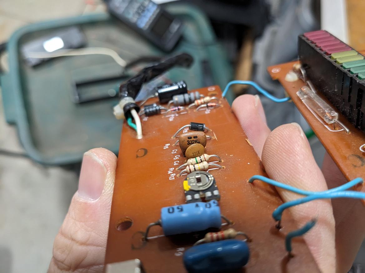
The signal seemed to stop around these capacitors, c3 c4 c5 below. I'm thinking these are supposed to be frequency filters for the tach input signal.
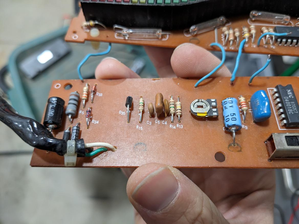
Then I probed those caps. I didn't remove them from the board so the readings I'm getting may be flawed, but for whatever reason when I try to measure them on my multimeter they all show 4nanofarads.
They don't look like they should all have the same capacitance to me...
In reply to Robbie (Forum Supporter) :
IANA EE, but wouldn't you need an ESR to check the caps?
Nice job testing the display...jelly of the Hantek!
I was just testing their capacitance with the mode on my multimeter. I figure the rest of the circuit may be getting measured as well because I didn't take them off the board.
I don't really know much about testing caps... I googled ESR and it seems like a cool tool.
Oh yeah, and I bought the hantek because you always need to buy $150 tools to fix $20 tachs. But I've been wanting an oscope for a long time and I like that the hantec can do a little signal generation too.
You have to disconnect one leg of the cap to measure or as you note you'll measure the circuit.
You were tracking an AC signal, correct? A capacitor will look mostly like an open circuit to DC.
Sketching out the circuit as Keith suggested will help you a lot.

Well, color me confused.
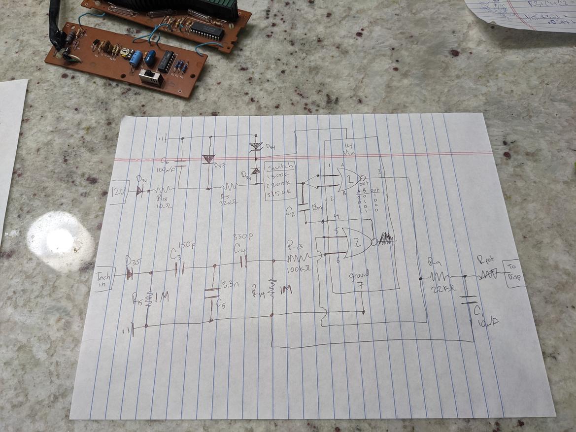
In the top left I think I understand the power circuit. Some massive capacitors and diodes to protect stuff if things aren't hooked up correctly. A 10ohm power resistor to protect against spikes. A zener diode to peg the chip voltage supply, probably at 5v. The switch is for 4cyl, 6cyl, or 8cyl. I do not yet understand why this switch is on the power side of the circuit, and not the tach in leg.
Bottom left is the tach signal leg. These capacitors look like frequency filters to me, and that makes sense - for a tachometer you'd really only be interested in about 10hz to 600hz if my math is correct, higher frequencies would exceed the 8k rpm this thing can read and therefore should be excluded. However, they seem in real life to simply filter out everything. There doesn't seem to be any signal at all when I apply the 60 hz signal to the tach in post and attempt to follow it with the o scope. Even after c3 I basically just have a flat line. This led me to believe that one of the caps there was faulty. However, if I rebuild this circuit in a circuit modeling tool, I basically get the same response.
Finally, following the logic gates in the chip is equally mind-numbing for me. I guess I can see how oscillations in the tach in side would cause oscillations in c2, which would then cause oscillations in the chip output, and that could get smoothed out by the c1 capacitor leaving a voltage for the display. But the switch doesn't seem to me like it would do very much in its current position?
Confusion sets in.
Ok, so I think I get the switch part now.
I suspect that the IV is being used as a "monostable multivibrator" which means that when you trigger it, it switches output state for a controlled period of time before returning to its original state.
So, say output is low 0v. Then a trigger comes in. Output goes high (vin, probably 5v) until the capacitor charges up through the select-able resistance resistor. Once the cap is sufficiently recharged, the output goes back to low 0v.
Which makes sense why the selectable resistance is where it is, as it will control the time the output is high for each tach signal. An 8cylinder engine has more coil pulses per rotation than a 4 cylinder engine, so it would need to keep the output high for a shorter amount of time to achieve the same output voltage at the same engine rpm input.
Edit, and this page confirms my suspicion!
https://www.electronics-tutorials.ws/waveforms/monostable.html
Using the calculation on that page (t = .7RC), with the 300k setting the multivibrator would be in the high output state for .00378s.
8000rpm in a 4 cylinder 4 stroke (2 coil fires per revolution) is 16,000 events per minute or 266.66 per second. (266hz).
266.66 hz is - you guessed it, .00375 seconds. So, at max input rpm for this tach, the monostable output would basically be like snoop dog, high all the time.
So now my main gap in understanding is the capacitor filter network on the tach in leg of the circuit. Need to figure out the design intent there, and then confirm if it is working.
This is awesome! Nice work!
Jesse Ransom said:
This is awesome! Nice work!
Thank you. I've been beating my head against the wall on it but feels good to at least make some progress.
Here is the circuit simulator i use. Incredibly helpful site. Like literally there are multiple years of undergraduate circuits class material covered on this free website.
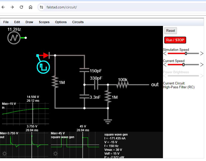
Anyway, I rebuild my "tach in" circuit leg and started messing around with inputs. I'm inputing a 60V square wave in order to basically get a 3.7V voltage spike out.
I'm wondering if this tach was build only for being connected directly to a coil, where you might see large voltage pulses like that. This might be confirming my postulation from last year that an electronic tach signal will not drive this circuit.
I think I'll try to 'skip' some of the caps and drive the IC more directly with my electronic tach signal and see if that works...


