


I’m in the final stages of designing the 3rd element for the LMP360, and I think there is much confusion about wheel rate calculation because I believe one of the equations generally in use has an error. Additionally I’ve always kinda known why this equation is used but never really derived it myself to really UNDERSTAND it. This equation is so prevalent that I originally did some of the calculations for the LMP360 using it, and don't want anyone else to make the same mistake, or worse still buy springs based on an incorrect calculation.
We've all probably seen this graphic (or one similar) and equation for Wheel Rate.
https://i0.wp.com/suspensionsecrets.co.uk/wp-content/uploads/2018/05/damper-angle.jpg?w=750&ssl=1
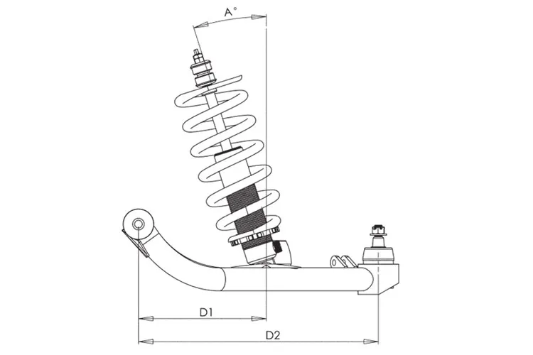
Where IR is the installation ratio and is D1/D2.
![]()
I have also seen MR used interchangeably with IR in this equation. I have seen this equation used by many places and referenced in many resources when you search "Suspension Installation Ratio" or "Suspension Motion Ratio". It is prevalent enough that It is widely used.
I believe the correct equation (and the one I am using) is below and I will show why I think that and you can review and comment.
![]()
Where MR is:
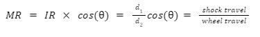
The big difference is the cos(∅) term ends up squared which depending on shock layover can have a large impact on your results.
In order to see why I think there is an error and to provide full bread crumbs to those following along we are going to have to derive the wheel rate equation. Don't worry this will be fun (narrator:it isn't) and you will be able to readily see and understand why the MR term is squared which often is just a leap of faith in spring rate articles.
To start we need a free body diagram of a sprung corner. Free body diagrams are used to evaluate mechanical systems. You make a simple model and assume that the item is at rest and you can then evaluate the forces acting on that object based on it’s geometry. We are going properly simple here.
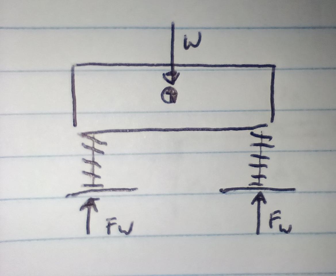
A simplified car with suspension is just a block with springs. The forces on this system have to balance. The Force at each wheel has to balance with the vehicle weight.
![]()
Ignoring weight distribution:
![]()
We will simplify it further by only looking at ¼ of the car and draw another FBD.
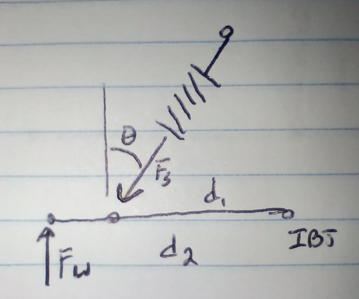
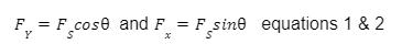
There is a force at the wheel that is the sprung weight of the car. The compression force in the spring has to counteract that. If we label the forces on our FBD we see that the spring acts at the angle of installation. Forces are vectors meaning they have a magnitude and direction. For an angled force we can resolve the horizontal and vertical components of the force. The magnitude of those component parts scale based on the angular change of direction.
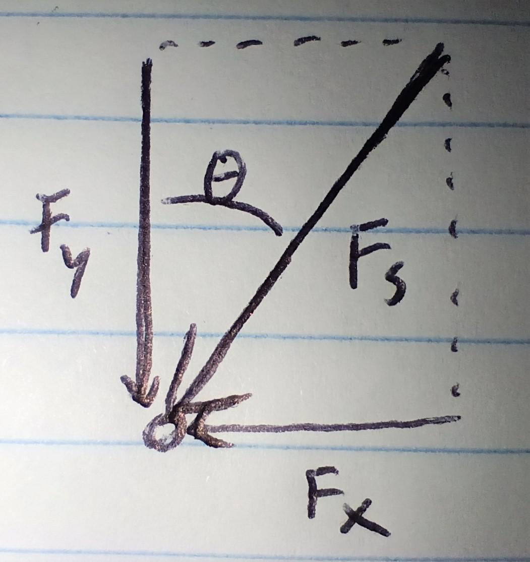
It's best to look at it as a triangle with the magnitude of the vectors as the edges. In this way you can clearly see the horizontal and vertical components. The magnitudes can be determined using SOH-CAH-TOA rules for a right triangle.
Now we go back to our FBD and focus only on the Lower A-arm.
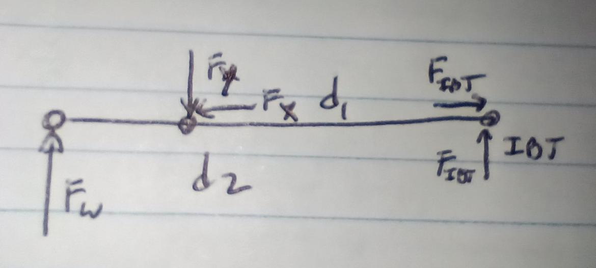
The system is at rest, so all forces must be balanced and at any point on the FBD the moments must equal 0 otherwise the car would rotate perpetually. Note we are only evaluating the forces on the A-arm here because that's the boundary of our FBD. Moments are Radius x Force (RxF) I’m doing clockwise moments as Positive, counter as negative.
![]()
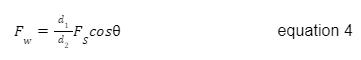
Here the radius of application for the forces Fx and Fx/y at the IBJ are 0 so they drop and we get
![]()
We can sum the forces on the A-arm and determine the magnitude of the Fy and Fx forces at the IBJ. They are just straight summations, X forces = 0 and Y forces = 0. But we don’t need to do that for what we are attempting here.
If we substitute equation 2 into equation 3 we get:
Now we are getting somewhere to something we care about which is comparing the Fs to Fw.. The force of a linear spring is a function of it’s displacement and it’s rate.
![]()
For simplicity of equations I will use L for the change in length. So if we substitute this relationship into equation 4 and rearrange it slightly we get the following.
![]()
What we are trying to find is Kw, if we set Lw=1” we would be left with the following:
Equation 5 is so close to an equation with all integers and therefore a solution. We just need to figure out Ls for a 1” displacement.
Looking at the diagrams below:
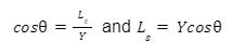
We cannot directly determine the change in shock length, but using similar triangles we can figure out Y.
From Y we can approximate Ls again using a triangle by zooming into detail 1.
The vertical displacement of the shock is the Hypotenuse of a right angle triangle of the same angle of the installation angle. Again using SOH-CAH-TOA we get:
Subbing the solution from equation 6:
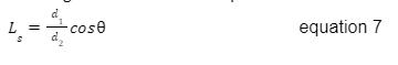
And finally going back to equation 5 we get:
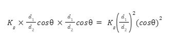
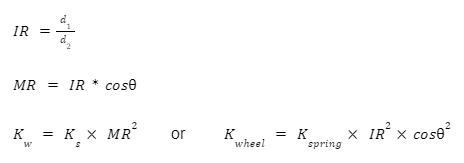
Which gets us back to my original claim:
Checking math we can replicate the original FBD and have a installation angle of 0 and a IR of 1 (d1=d2) and get that the Kw=Ks. Similarly because Cos of angles of 0 is 1 and 90 is 0 we would expect the effective spring rate to drop rapidly as the shock is layed down. Until eventually we would get Kw=0 for a spring layed completely over.
I believe this is the correct equation, and I think it shows how and why the MR/IR term is squared. The MR is squared because the Force at the spring has to react the force at the ground. The Force at the spring is reduced once by the MR due to the leverage disadvantage, AND it is reduced again by the fact that it’s displacement (Spring force is Rate x displacement) is lower again by the same MR.
Here is a chart I made of Kwheel calculated for an arbitrary spring of 500lbs/in at a fixed MR but variable angles.
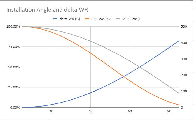
You can see for Large angles the calculated difference is quite high. For small angles (Like say strut suspensions) the difference is low, <10% and probably basically irrelevent. But for more layed over shocks beyond say 10 degrees the difference because impactful.
So what to do with this information? If you are going to use the geometric evaluation, use the equation that squares the cos. Or better yet, just calculate or measure the actual spring displacement for wheel displacement and use that as your MR in the calculator. Then you can ignore the cos angle correction.
TLDR:
Use this equation for calculating Wheel Rates:
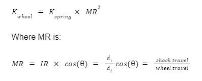
MR is squared because the mechanical advantage of the A-arm operates both on Force AND displacement of the spring.


