[Editor's Note: This article originally appeared in the March 2009 issue of Grassroots Motorsports.]
Alternator changes and upgrades are among the most common underbonnet modifications performed on British cars. We’ve seen hundreds of these swaps performed through the years. While some are appropriate and effective, we’ve witnessed—and fixed—too many that have ultimately caused some sort of expensive problem: an electrical meltdown, a spinning part thrown from the car, or maybe just something sticking itself into the radiator.
Bottom line: We think most alternator conversions are a waste of time. In fact, they’re often dangerous.
We know, them’s fightin’ words. Everyone wants a reliable alternator, and those Lucas contraptions don’t seem to hold up or generate enough current. To put it simply, they just aren’t the kind of outdated technology we want to see when we raise our hoods.
However, anyone who took debate—or made fun of the debate kids—in high school knows that you can’t come out with fightin’ words without backing them up. So, allow us to state our case.
It’s clear that many modern alternators put out more current than their old Lucas counterparts. You could also argue that the newer units hold up longer. However, the alternator itself isn’t the problem in most alternator swaps; it’s the wiring and the mounting that get people every time, making smoke and nasty sounds almost inevitable.
Think about this: If you install a modern, 80-amp alternator and use the stock wiring that was designed for a 36-amp alternator, what’s the inevitable outcome? Many people reason that if the accessories will still require the same amount of current from the new alternator as they did from the original, then it’s safe to use the stock wiring.
This logic fails to take two words into account: current potential. If a component ever fails or a dead short accidentally occurs, something will attempt to draw the full current capacity of the new alternator. What does this mean for a big portion of the wiring harness? Melting, smoking and burning.
Here’s something else to consider: Slapping on that alternator with some hardware store bolts and getting the alignment “pretty close” will work for a while. Eventually, however, something’s going to break, let loose or fly off, and that alternator will be flopping around, waiting to short out or preparing to hit something.
Now that we’ve laid out our case and made our point, let’s set things right and talk about the correct way to upgrade to a modern alternator. A good conversion consists of three important elements:
- Picking the right alternator.
- Making a very solid mount and adjuster.
- Wiring the alternator correctly.
Picking the Right Alternator
Some alternator conversions make more sense than others. For example, some of the early alternators with external regulators aren’t available anymore, so your only choice is to convert to something else.
Swapping a generator for an alternator is another advantageous move. Many generators can barely keep up with the charging demands of the headlights and starter, so they probably won’t cut it if you’ve added a stereo or a big ignition system. Most generators also use bushings instead of bearings; an alternator with a bearing-equipped rotating mass is a better option.
When it comes to generators and outdated alternators, we feel that it’s usually best to do what the factory did: Upgrade to a good alternator.
If you have an MGA or early MGB, install the factory alternator from a later MGB. For a Triumph TR or a Jaguar E-type, do the same thing: Look toward a later model for a solution. You can source the stock mounting and alternator instead of engineering them yourself, saving a good deal of time and effort. You’ll still have to modify the wiring, but having two out of three jobs done up front ain’t bad.
If you want more output than an OEM alternator, then it’s time to do some careful shopping. Many people use mid- to late-1970s GM alternators because they’re common, inexpensive and rather durable. Late-1970s Bosch alternators show up quite often, too—especially on MGBs, since the conversion is nearly a bolt-in proposition.
For our money, however, we would pick a compact Japanese alternator and do things right. While it’s a bit hard to find quality data and specifications on alternators, we try to match the unit to our particular application.
First, we find an alternator that will physically fit; usually, the more compact it is, the better. Then we consider the pulleys; while many modern alternators feature pulleys for multi-groove serpentine belts, we want one that has—or can at least accept—a pulley that uses a conventional V-belt. Ideally, our alternator will work with the stock belt; this way, we can grab a replacement at any auto parts store.
Next, we make sure we’re not going to spin the alternator too quickly or too slowly. We also try to find a multiple-wire alternator, as the one-wire pieces don’t have provisions for a dashboard warning indicator—also known as the idiot light.
Most Lucas alternators produce less than 40 amps of current, but modern alternators typically produce much more—often starting around 60 amps. As we’ve already hinted, most of our classics don’t need tons of juice, so we like to stick with a lower-output, compact alternator. We’ve found that the Denso alternators used on Japanese cars fit the bill very well. Our favorites are the ones that came on ’90s-era Geos and the ones that Gustafson Specialty sells.
Make a Solid Mount
This is where conversions often fall apart. Many swappers choose the right alternator, but then they blow the deal by mounting it poorly. The alternator must be mounted so that it’s perfectly lined up with the other pulleys in the system. The mount must also be strong and capable of properly distributing stresses.
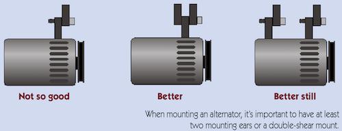
We always mount our alternators on double ears or in double shear; too often we see single-ear mounts that eventually overstress a fastener or mounting ear. While many swaps rely on the ear of the water pump as a sole mounting point, we always use a second point for reinforcement, usually using 3/16- or 1/4-inch steel for our brackets.
We also insist on close tolerances with all fasteners as well as hardware that properly matches with the holes. People often make the mistake of using metric bolts in American unit-sized holes and vice versa. This can quickly result in flopping, rattling, shaking, shifting and breaking.
Wire It Right
Once we’ve sourced the right alternator and correctly mounted it, we can tackle the wiring. Our modern alternator has more current potential than the original wiring can handle, so we need to rewire the system. Since we start this new wiring from scratch, we also like to incorporate some additional safety into the system.
Our method goes like this: We find the maximum current output capacity for our alternator, then pick an appropriate master charging wire size. We usually use the factory color for this wire, which is brown in Lucas systems.
Here’s where the extra safety comes in: We add a fusible link to this master charging wire. A fusible link, as the name implies, works as a fuse. If anything goes dramatically wrong, the fusible link will sacrifice itself and melt away, effectively saving the more expensive components. Once we have selected our main charging wire and fusible link, we use the original wiring setup as a guide to install them—usually from the alternator to the starter solenoid.
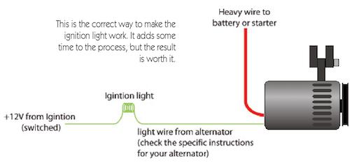
Assuming we can get our hands on a multiple-wire alternator, the next part of our wiring job is to make the dashboard’s idiot light work properly. This usually takes a little research, but most multiple-wire units work by becoming “excited” with external voltage.
One side of the idiot light is linked to the alternator, while the other side is linked to positive 12 volts. (Technically, the voltage is closer to 13.5-13.8, but we’re sticking to the nomenclature of our nominal 12-volt systems.) When the key is in the On position and the alternator is not working properly, a ground condition occurs and illuminates the idiot light to indicate a problem. When the key is on and the alternator is operating properly, the alternator sends positive 12 volts back to the light, extinguishing it.
To deliver the necessary volts, we run an exciter wire between the alternator and the idiot light; on Lucas systems, this is usually a brown wire with a yellow tracer. If a car features a voltmeter or ammeter, however, no wiring modification is required to get the idiot light working; these gauges can usually pick up their signals downstream of the alternator wiring.
Our last step is to deal with the now-abandoned OEM wiring. When it comes to this task, there are two good choices and one bad one. The bad one is to let the wiring hang and potentially short out. A better choice is to disconnect the wires, then tape and hide them. We do this if we think there is a chance the car might return to the OEM configuration. After all, we wouldn’t want to complicate the process by cutting off the wiring components.
The other good choice is to completely remove the wiring from the loom so it doesn’t create any risk or confusion for anyone in the future. This usually requires cutting apart the loom’s outside wrapping and then rewrapping it, which is no trivial task. It does make things neater, however, so we often take this route.
A Step-By-Step Guide
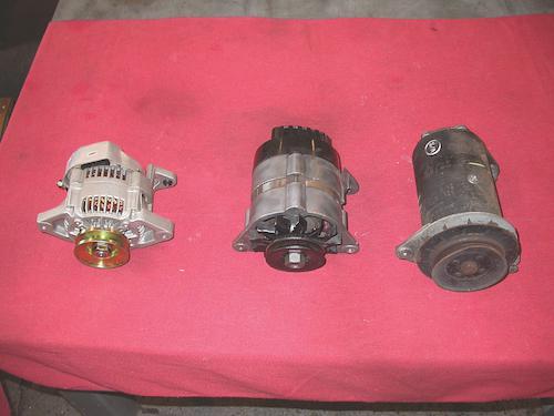
1: The evolution of our charging systems: A Lucas generator (right), a Lucas 16ACR 32-amp alternator (middle), and a modern Denso 55-amp alternator (left).
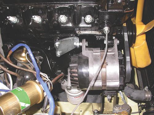
2: Our 1971 Modern Midget project car originally used a generator. When we reassembled the car, we swapped the outdated unit for an OEM 1973-spec Lucas alternator. Since we were rewiring the car anyway, we upgraded to a 1973 Midget loom.
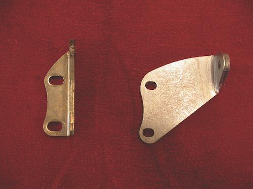
3: To simplify our swap, we ordered a pair of alternator mounting ears from Moss Motors (Part No. 130-115, right).

4: Alternators require a solid mount to prevent vibration-related damage. After making some quick measurements, we roughed out a mount from some 1/4-inch cold rolled steel.

5: After some more measuring, cutting, welding, drilling and test fittings, our new beefy mount was starting to take shape. We just needed to give it a clean look with some grinding and painting.

6: Once we cleaned up the edges and applied a fresh coat of paint, the mount was ready for installation.
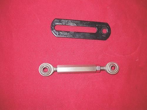
7: Instead of using an OEM slider-style adjuster, we fabricated a nicer component using a pair of rod ends and coupler sourced from McMaster-Carr.
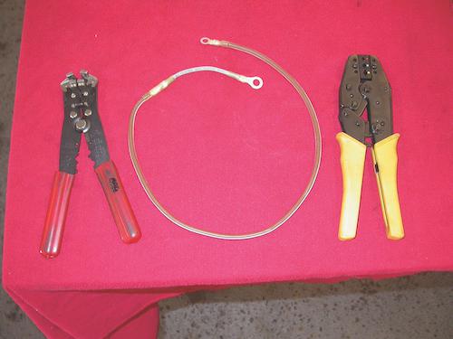
8: Now it was time to address the wiring. Since our 60-amp alternator could potentially melt the OEM 12-gauge alternator wiring, we made up a new main charging wire using 10-gauge wire along with a 14-gauge fusible link. We stuck to the factory color code—brown in this case.
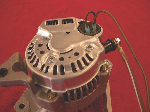
9: We also made up a subharness for the exciter circuit and the charging light. These subharnesses vary from alternator to alternator, so it’s important to do your research. In our case, we used a schematic provided by Gustafson Specialty. We made up the 16-gauge wiring using the Lucas code—brown with a yellow tracer.
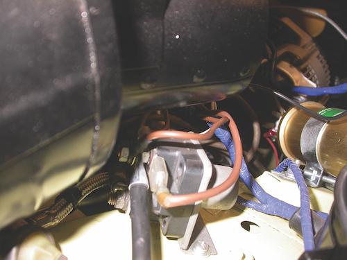
10: We connected the OEM charging wires to the externally mounted starter solenoid, which is the main wiring junction from the battery. We then removed the OEM wiring from this junction and wired in our new main charging wire
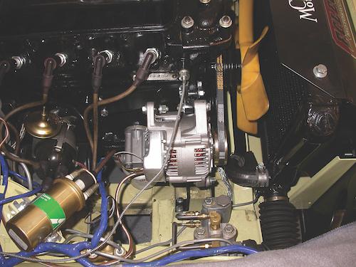
11: The final installation looks stock. Since we took the time to tackle each step correctly, we now have a safe, long-lasting solution that uses the factory belt.
All Good Things Take Time
We originally stated that most alternator conversions are bad news. However, we also showed you the proper approach to making your swap the exception. Doing things correctly will take additional fabrication, wiring and time, but the results will be worth it: You’ll end up with a safe, long-lasting and easy-to-service conversion.
More like this
Comments
Sorry Carl,
Your article was good as far as it went, but a good number of post-war British cars had tcchometers that were driven from a small gearbox off the back end of the generator, and you fell short by not dealing with this issue.
The Denso is far from being an ideal alternator. Many of the small models were single wire, but more importantly, the rectifier unit, was packed around the rear of the unti, thus preventing the adaptionof the tach drive take-off.
Gord Clark
Rockburn, QC
several old MGs from '34 to '54

Jpsbgt
New Reader
11/7/21 11:26 a.m.
One in a million application Gord.

wspohn
SuperDork
11/7/21 11:35 a.m.
Actually, it wasn't just the 30s - 50s cars. 60s/70s Austin Healeys and the TR6 also drove the tach off the dynamo.

Bardan
New Reader
4/1/22 1:56 p.m.
1. If the wiring is bad, it should be repaired wheather using a modern alternator or an old generator. If wiring is bad, repair/replace the wiring. (BTW lots of old splicing and wire butchery to add stereos and other components adds resistance and is bad). Also GM makes a great electric conduit thats easy to install and cheap. Use it wherever wire chaffing may occur.
2. Some old Britt cars have very few fuses. I had an Austin Mini with only 4 total fuses and the Jackass previous owner rewired it so only 2 worked. Add fuses as needed and check for wiring problems.
3. Lucas generators used on MGs will only put out 12 amps after going through an external regulator and old high resistance wiring. Add the amperage needed for ignition, fuel pump, radio, lights and wipers. Factor in wire resistance and you need more than 12 amps to power it all. A long night drive in the rain might kill the battery. Sounds like a modern alternator would be nice to have.
4. A properly working component, say a headlight will only draw a certain amount of amperage, say 5 amps. If the Alternator puts out 80 amps, what happens to the rest? The internal regulator of the alternator regulates as its supposed to,. No it doesnt burn up wiring.
Bottom line, if you like to drive your Britt classic, a good alternator helps. FYI the Delco 63A alternator was used in most GM cars and trucks from 69 to 85 (we know how many cars GM made then). Every junkyard has baskets of them and they are tough reliable units. I'd trust one of those before other alternators.

BBGun
New Reader
6/21/22 12:30 p.m.
I have no personal experience with this product but a more original looking alternative might be a "GenerNator". It a Lucas generator body containing an alternator internals. I would be interested to hear from you or readers that have tried one.
https://gener-nator.com/

wspohn
SuperDork
6/22/22 1:14 p.m.
I considered one of those alternators-that-look-like-generators when I was vintage racing. The powers that be were concerned with appearances, didn't want vintage cars to look modern so ruled against obvious changes like that.
My concern was that when you are shifting just below 8,000, you can spin the guts out of a dynamo pretty quickly,. I solved my issue by finding a substitute pulley that spun the generator more slowly than normal. We had some people that thought it was worthwhile gutting the generator to slightly reduce drag and get some small undefined amount of extra power from that, but they quickly ran out of friends willing to push start them in the pits when their batteries dropped too low to start the car.
I used one of these alternators that look like a Lucas generator on our Lotus Elan project and it looks and works perfectly.
I don't understand the beneifts of a fusible link over a fuse or a circuit breaker. It appears that it would just be harder to fix in the event that something went wrong. Wouldn't something like a 30 amp automotive circuit breaker (self-resetting) be an ideal solution to put in line between the alternator and the the starter?
Displaying 1-8 of 8 commentsView all comments on the CMS forums
You'll need to log in to post.


 By Carl Heideman


