Presented by Nine Lives Racing
1 2 3
nocones
nocones UberDork
11/4/21 2:53 p.m.

This is the first in a likely 4 part series where I ask all kinds of questions and hope for FREE Aero design from the experts hiding on our board.  Part 1: Front Element, Part 2: Topside and Front Underfloor,  Part 3: Diffuser, Part 4: Rear Wing

The car is first a challenge car so the initial performance objectives are MAX possible downforce at <80 MPH.  Remove-able elements for Drag reduction during the Drags are acceptable until I am told otherwise.  

That said the other goal for the car is to run it at UTCC and use it extensively at HPDE and possible TT events with Gridlife and the others. 

I would like to develop an Aero platform that with some amount of part changes can be appropriate for this.  I recognize the optimized Wing sizes for <80 MPH might be prohibitively draggy for a 160-200HP car at 120+ MPH.  So the goal would be to keep the Areas between the wheels and probably the diffuser unmodified.  

I recognize that there is going to be some bleed over between "sections" and thread conversations as each Aero element relies heavily on the parts that address the air before them.  My hope though is by dividing them up more detailed discussions that are more applicable to other projects can be had.  I'm starting with the front element because it addresses the air first.  

I'm open to basically anything but would prefer to not do things like heavily modify the chassis or change the suspension design to introduce more space for aero parts.  There are no class rules that need to be observed for this car, with the only exception being I don't want to do Powered Aero (Sucker car).  Although challenge legal it has 0 application out side of the challenge so it really doesn't make sense.  

So now onto the discussion at hand, the Front Element.  The car front is designed similar to a LMP car with a elevate footbox that is the same width as the inner suspension pickups.   That foot box is 8" off the ground, 6" above the floor under the driver, back to the seat 24" behind the front axle centerline.  I've attached a few pictures of the front for reference. 

Ouside of this chassis the car is basically an Open wheel car with fenders only above the tires.  The fenders are not currently integrated to the body so that integration should work together with the front element. 

Due to the Open-ness of the chassis/suspension and front fenders a Front element with a diffuser or expansion section and general wing profile seems to make more sense then a full flat foor splitter.  So what general design would work best?  I've looked at several vehicles for input and and inspiration but need guidance so I don't wind up making something that is just Aero Themed but actually functions.

Cody Loveland Enviate Pikes Peak Hypercar: 

From this car I like the 2 element Expansion element inboard of wheels in front of suspension.  Upward turned front edge of "splitter" to give it overall a wing profile.  What do we think of "infinite" endplateless wings?  Obviously overall width is a negative for an Autox car and it may make sense to give up the surface area for narrower width.   Is the tapered shape with the solid inner edge of the fenders necessary to even make this concept work? Air seems like it would be divided by these inner fender extensions with some being swept outward to feed the infinite wing and the rest going into and over the inner wing area.

Bently Continental GT3 Pikes Peak

This is a more "Traditional" treatment of the outside of the wing element.  Similar designs have appeared on many unlimited TT cars.  Again O/A Width is a concern but is this a better alternative to the "infinite" wing?  

Audi R15 LMP1
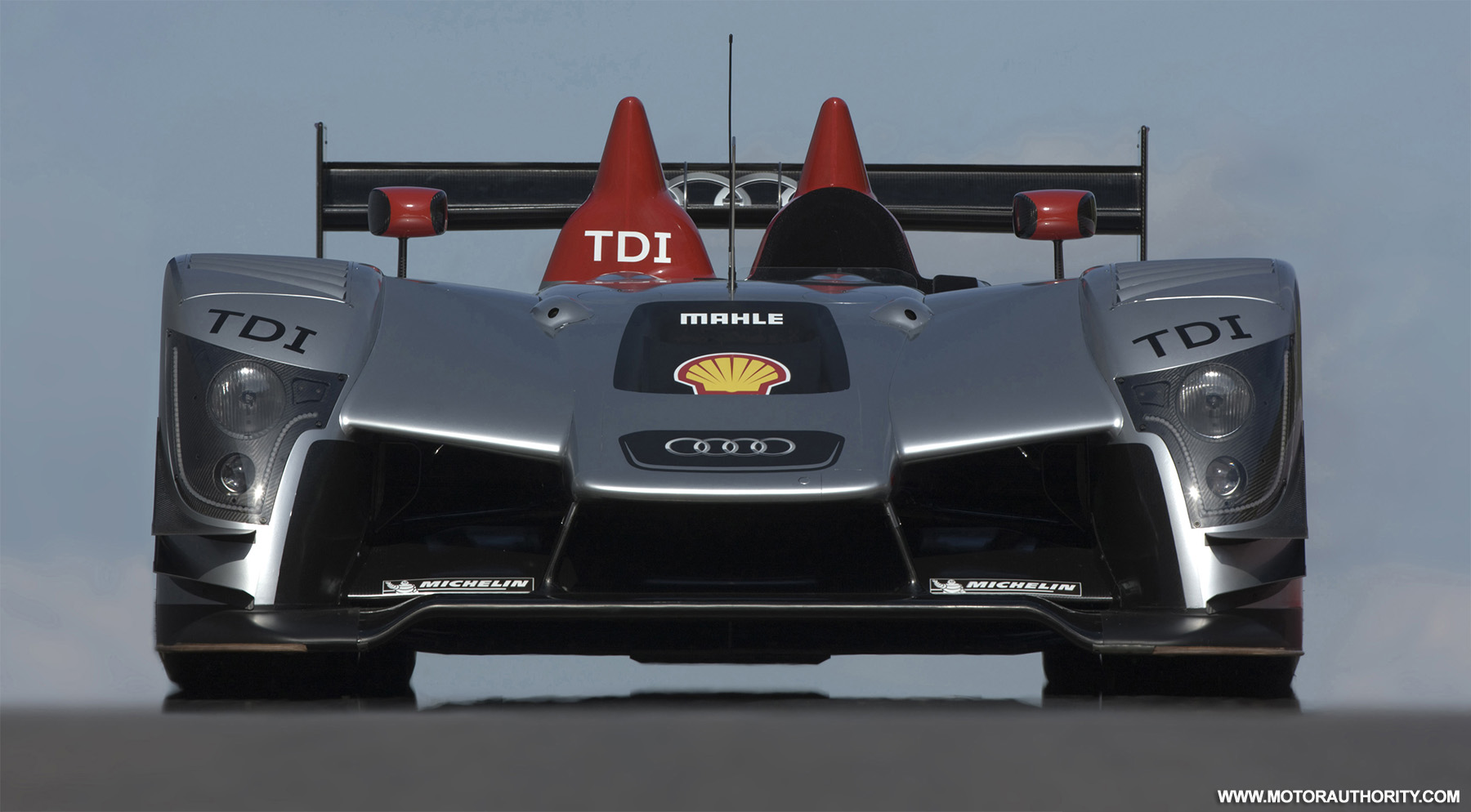
Similar treatment ot the Enviate inside the fenders.  Multi element expansion with a break before the infeed to the underfloor areo.  The R15 has the overall raised center (Some of this width is rules driven) that feeds/energizes the underfloor.   Traditional diveplanes outside fenders area.  

Formula 1 style wing with endplates
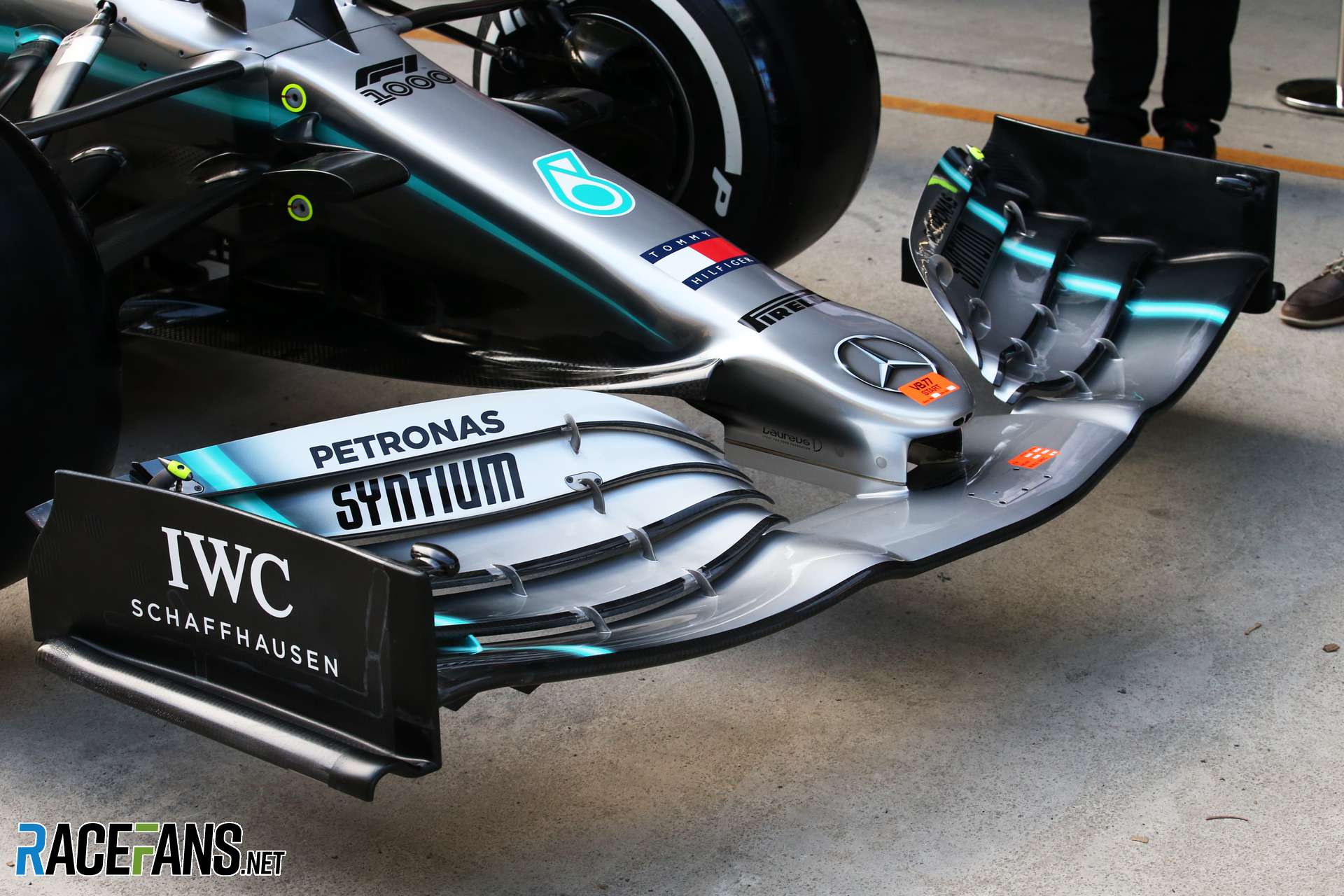
Since no rules does it make more sense to go with more of a True "Open Wheel" wing and then a simple "cape" over the top that divides some air to go over the car vs that that addresses the top side of the wing.  This is more the design I have been sketching, but obvioulsy significant amounts of the wing wind up intersecting with the front of the fenders which overall have to be kept to maintain Challenge and "non-open wheel" Track use legality.   Does it make sense to use endplates (And should I add a vortex generator?).  I don't have the "FIA control section" to deal with but obviously the middle 20" or so is under the footbox so the effective expansion area is limited.

Praga R1R

Aesthetically I really like this front, but from a Aero Aggressiveness it's probably the tamest.  The R1R has a basically flat floor with minimal under nose expansion.  

Overall I like the Aesthetic of the Higher nose treatments vs the 919 type low nose.  Stuff like the Audi R15 and Praga R1R to me looks the best and all else being equal I would like to navigate towards a similar look for the LMP360.  

So yeah, Lets talk about what would work best.  I know people have provided feedback before and I just want to kind of expand on that.  I leave you with the most current "concept" design that still needs lots of tweeking.  As I start to build stuff the fabrication will move back to my build thread but I can document the design here. 

bobzilla
bobzilla MegaDork
11/4/21 3:54 p.m.

There's a lot of words here and I didn't read them plus I'm a bit of an idiot..... with that out of the way I like where you're going with this. 

stafford1500
stafford1500 Dork
11/4/21 4:21 p.m.

I will ponder your request and design limitations a little before I post up a probably long-winded reply.

Glad you are working to keep the build active and not letting it get dusty during the post-challenge winter months.

Thinkkker
Thinkkker UltraDork
11/4/21 5:59 p.m.

I think a combo of what you have will work.  The Enviate actually looks like the simplest to model up.  The first issue I can see is that I think the fender supports as they may need modifications.  I think the lower support may need to lay more horizontal and the upper to drop and extend flat to the car.  I only say that, just to give more area for a wing to reside.

If you look at the R1R, they have supports extending to support the splitter.  This may be ticket and if you tie start making higher downforce.

Remember to vent the top of the fenders, and then on the inside you can just plate the frame to seal it up. 

I would start at the plating.  Thats the easy part.  Unfortunately, then it gets a lot more difficult. 

maschinenbau
maschinenbau UltraDork
11/11/21 9:24 a.m.

FolloWing... I really like what you've started designing, at least from an aesthetic point of view because that's the only one I can provide. Structurally, since your fenders are cantilevered pretty far from the body, I imagine you'll need a significantly strong lateral cross-member(s) at the very nose of the car to support the aero loads. You can probably hide it within the lower dam (1st floor?) or the wing-like feature between nose and fender (2nd floor?)

stafford1500
stafford1500 Dork
11/11/21 9:28 a.m.

I still have not had a chance to sit down and put something together on this thread, but it has been on my mind. Dang work getting in the way of important stuff...

sleepyhead the buffalo
sleepyhead the buffalo Mod Squad
11/11/21 5:54 p.m.

wow, I must have been having a hard time last week... and didn't even notice this thread.  I'm going to stick to "structures" first...

so, uh... have you ever heard of "PMF" ?

nocones
nocones UberDork
11/12/21 12:39 p.m.

I have time until things start getting fabricated, I understand people or busy and this takes a while.

Sleepy, I have not heard of PMF probably in the context you are thinking but I'm always down to learn.

Pete Gossett (Forum Supporter)
Pete Gossett (Forum Supporter) MegaDork
11/12/21 3:25 p.m.

In reply to nocones :

Not that you need another project or two for your project car, but if you built a small wind tunnel & some scale models of your car to test out in it, I think that would score even more points with the concours judges. 

sleepyhead the buffalo
sleepyhead the buffalo Mod Squad
11/12/21 4:21 p.m.
Pete Gossett (Forum Supporter) said:

In reply to nocones :

Not that you need another project or two for your project car, but if you built a small wind tunnel & some scale models of your car to test out in it, I think that would score even more points with the concours judges. 

I know the LMP360 is small... but he's going to run into some pretty major ReynoldsNumber effects, which are going to be make the data... 'not so useful'

a water tunnel, otoh, could work... but I've also seen what happens with one of those if you mess up.

sleepyhead the buffalo
sleepyhead the buffalo Mod Squad
11/12/21 4:27 p.m.

PMF frequently stands for "Poor Man's Fiberglass"... and it's effectively 'watered down wood glue' and some form of 'draping fabric'.  Frequently, I've seen the recommendation to use cloth/burlap dropclothes from 'the home center'... or another option might be burlap feed bags from TSC?

I haven't quite gone through the numbers of cost... and its possible the wood glue is too expensive?  but, it's certainly 'less toxic' to work with... and would make it easier to realize some fairly radical foil-shapes, so long as they had some internal structure to 'help out' (aluminum?)

this was a concept I was beginning to explore in order to build a VW bettle-based Bugatti Type 32... before I found out Stafford and I independently had a similar challenge idea; only with his being corvette-based.  blush

You could probably use that for the "elements" between the nose and the fenders.  There might also be a way to use it in the front part of the splitter, as well, depending on... things.


I think one of the most useful strategies is to build the splitter/floor based on the later track use... maybe with some ability to adjust/tweak the exit on the between the front fender, the tub, and the sidepod.  Then you/I/stafford try to come up with an "aggressive" element/elements that sits in front of the control arms and between the fender and the nose.  With the idea that those elements would be removed for the DragPasses, but the splitter/floor remains.  Then there might be two different rear wings... one for autoX and one for 1/4mile so the car stays balanced out... and it has lower Cd-drag.

maschinenbau
maschinenbau UltraDork
2/14/22 12:33 p.m.

Buuuump

stafford1500
stafford1500 Dork
2/14/22 5:11 p.m.

Only three months later and I am still up to my neck in alligators with work. Maybe once the cars actually get on track this week I will see some light at the end of the wind tunnel... and be able to add to this discussion a little more.

sleepyhead the buffalo
sleepyhead the buffalo Mod Squad
2/14/22 7:52 p.m.

I thought I might bring up some points on these "inspiration" designs... so that it's a little easier to see what elements might be helpful/hurtful for Challenge car.  If i have some time, I'll see about some mark-up of the three images of LMP360 from the first post.

One main takeaway to keep in mind with all of these, except the Hypercar, is that the rules very much determine many of the design parameters for why things look the way they do.  And, while the Hypercar has fewer rules... the fact that it's going to be at 10,000ft and wanting downforce drives the design in some ways.  However, although they may have a V.design of 120mph compared to your 60mph, he fact that "standard air density" at 10kft is 0.0017555 slugs/cubic.feet compared to 0.0023769 slugs/cubic.feet at SeaLevel... means you're a bit closer to their design ReynoldsNumber than you'd expect.

nocones said:

Cody Loveland Enviate Pikes Peak Hypercar: 

From this car I like the 2 element Expansion element inboard of wheels in front of suspension.  Upward turned front edge of "splitter" to give it overall a wing profile.  What do we think of "infinite" endplateless wings?  Obviously overall width is a negative for an Autox car and it may make sense to give up the surface area for narrower width.   Is the tapered shape with the solid inner edge of the fenders necessary to even make this concept work? Air seems like it would be divided by these inner fender extensions with some being swept outward to feed the infinite wing and the rest going into and over the inner wing area.

I suspect that you're not going to want an "infinite end plate" design... and that constraining the front element to conform... 'relatively' close to the fender line will be helpful in cutting the shortest distance between cones... which might-could become more important as the downforce allows you to corner/slalom faster.  The key will be... to design this such that you can add an outer portion that attaches on for when the car is "track focused".  The sharp forward edge of the fender is primarily setup to provide "clean" air in to the element between the fender and the nose; while maximizing the amount of air that's pushed sideways and through infinite-endplate (while also accelerating the flow during the push laterally, thereby achieving more downforce through those endplates.

You could do the opposite of this to force more air through a '2nd element' between the fender and the nose, while limiting the 'forward-wide' auto-x constraint;  if did this with a fairly easy to fabricate "fence", of limited thickness, between the top of the 'first element' and the bottom of the headlight... you could shift it's location inboard/outboard depending on track vs. autox use.

Bently Continental GT3 Pikes Peak

This is a more "Traditional" treatment of the outside of the wing element.  Similar designs have appeared on many unlimited TT cars.  Again O/A Width is a concern but is this a better alternative to the "infinite" wing?  

An outbard canard like this might be a worthwhile treatment (even without the lower splitter plate)... assuming that you can get the bottom edge of the outboard canard such that it's above the top of the cones GRM uses.  I have no idea how practical that is though.

Audi R15 LMP1

Similar treatment ot the Enviate inside the fenders.  Multi element expansion with a break before the infeed to the underfloor areo.  The R15 has the overall raised center (Some of this width is rules driven) that feeds/energizes the underfloor.   Traditional diveplanes outside fenders area.  

There's  a couple important things to keep in mind on this.  Stafford's already related how have the outboard section of the splitter lower in front of the wheels is important for drag.  Another thing to bear in mind with any LMP car like this, is that the LeMans rules specifically requires that bodywork 'shroud' the suspension arms from view from the front and from above.  That's a primary reason behind the fill-in panel between the fender and the nose... and some of the design of the bodywork through the suspension area.

One final thing to note, is that Audi pull a little bit of a fast one on the rules with this design... and a portion of the air entering the central intake under the four-rings badge exits where the shell logo is... which means that section is effectively a raised front wing element.

Formula 1 style wing with endplates

Since no rules does it make more sense to go with more of a True "Open Wheel" wing and then a simple "cape" over the top that divides some air to go over the car vs that that addresses the top side of the wing.  This is more the design I have been sketching, but obvioulsy significant amounts of the wing wind up intersecting with the front of the fenders which overall have to be kept to maintain Challenge and "non-open wheel" Track use legality.   Does it make sense to use endplates (And should I add a vortex generator?).  I don't have the "FIA control section" to deal with but obviously the middle 20" or so is under the footbox so the effective expansion area is limited.

As I mentioned within the Hypercar commen, I think you can utilize endplates ahead of the fender to "encourage" the air to split inboard/outboard to better fit your interests (especially considering the difficulty of trying to recontour the front radius of the fenders (for now).  I'm not sure going beyond two elements will be worth the effort... especially since two larger elements will help boost the relatively ReynoldsNumber... which will help them achieve higher Clmaxes despite the lower vehicle speed.

Praga R1R

Aesthetically I really like this front, but from a Aero Aggressiveness it's probably the tamest.  The R1R has a basically flat floor with minimal under nose expansion. 

The main thing I don't particularly like about this design is how far from the "lower element" the combination "upper-element"/fender-support is... which will reduce its ability to help take advantage of flow accelerated by the converging of the fender and the nose to keep it attached at "higher than exepected relative angles" on that upper/second element.

sleepyhead the buffalo
sleepyhead the buffalo Mod Squad
2/14/22 8:03 p.m.
nocones said:

The car is first a challenge car so the initial performance objectives are MAX possible downforce at <80 MPH.  Remove-able elements for Drag reduction during the Drags are acceptable until I am told otherwise.  

That said the other goal for the car is to run it at UTCC and use it extensively at HPDE and possible TT events with Gridlife and the others. 

I would like to develop an Aero platform that with some amount of part changes can be appropriate for this.  I recognize the optimized Wing sizes for <80 MPH might be prohibitively draggy for a 160-200HP car at 120+ MPH.  So the goal would be to keep the Areas between the wheels and probably the diffuser unmodified.  


Ouside of this chassis the car is basically an Open wheel car with fenders only above the tires.  The fenders are not currently integrated to the body so that integration should work together with the front element. 

Due to the Open-ness of the chassis/suspension and front fenders a Front element with a diffuser or expansion section and general wing profile seems to make more sense then a full flat foor splitter.  So what general design would work best?  I've looked at several vehicles for input and and inspiration but need guidance so I don't wind up making something that is just Aero Themed but actually functions.

I wanted to put those a bit closer together, because it could be helpful.

First bit that would be interesting/helpful to know (and isn't obvious from the photos):  Do the lower a-arms have any rake?

Another piece of data that will probably be helpful in some analysis (assuming we get to doing that):  What does the model show for the length of the 'splitter' from the front edge back to a point between the current front fender brace and the front edge of the a-arm (assuming a straight station-line along the forward mount of the lower a-arm)?

Finally:  How long would a element's chord be if it were mounted 1" above the splitter and angled up and back so that it terminated... say.. 4inches ahead and at the same height as the upper a-arm mount to the uprights?  And, what's a rough guess of the angle a section here would be at compared to "free stream" / "parallel with the ground" ?

nocones
nocones UberDork
2/15/22 1:02 a.m.

In reply to sleepyhead the buffalo :

I will try to get some dimensions tomorrow.  

The lower A-arms are Level front to back but droop towards the outer ball joints.  

I put some sketchup to the discussion you where having.  I hadn't considred directing Air INWARD toward the upper elements.  The stock Fender shape lends itself well to this.  I could keep Stock 360 geometry and have my Addition be the part that turns the air inward.  Here's an updated picture,  The Spliter/wing elements still need to be adjusted based on input and actual a-arm and front end geometry.

Thanks again everyone for the input and help.  I should be back to working on the car after this weekend.  And the front Aero is where I am planning to start.

jh36
jh36 Dork
2/15/22 3:16 a.m.

Just dropping in to say....impressive. Really impressive. 

tuna55
tuna55 MegaDork
2/15/22 9:01 a.m.

In to hear how this goes, sorry I missed it at first.

sleepyhead the buffalo
sleepyhead the buffalo Mod Squad
2/15/22 3:14 p.m.
nocones said:

In reply to sleepyhead the buffalo :

  I hadn't considred directing Air INWARD toward the upper elements.  The stock Fender shape lends itself well to this.  I could keep Stock 360 geometry and have my Addition be the part that turns the air inward.  Here's an updated picture,  The Spliter/wing elements still need to be adjusted based on input and actual a-arm and front end geometry.

So, to be clear, there's a couple reasons you don't see cars directing air inside the fenders.  There's suspension bits there to disrupt the flow, and make drag.  And, probably more often the reason, pulling it in, and accelerating/expanding that air means you're putting dirty air out over the "middle-ish" of the car... which will degrade rear wing performance.

I think, though, GRMChallenge... and AutoX speeds... and the stated goal of #MaximumDownforce... means that's a trade-off we can work around for now.

I'm going to attempt some "mark-ups", because I think what I'm advocating for is getting... misunderstood a little... since some of the original design idea is... "holding on".  And, I'm thinking about ways to slot these elements in "quick and dirty" style... using some of last year's support structure... and not putting in a 'full droop over' section between the nose and the fender.  Instead using that area to pack in one or two elements at high cambers/angles...

nocones
nocones UberDork
2/15/22 6:15 p.m.

In reply to sleepyhead the buffalo :

I see what your getting at now.  I will play again with CAD to adjust it.  I've always kept the over the arms infill piece just because it's been part of the image since the beginning.  But seeing the multi element design your suggesting I think it can look just as crazy while being better function.  

If I'm interpreting your drawings correctly your front end treatment would be similar to this version of the R18.

It appears there were a few versions of the E-tron but I believe this one is more like your multi element Wing as the infill with just a shroud over the A-arms.  So like your 2nd image.  And I'm down with this look it's sufficiently weird for the goal.  

maschinenbau
maschinenbau UltraDork
2/16/22 10:46 a.m.

Thank you, this is some nice reading. Please carry on.

sleepyhead the buffalo
sleepyhead the buffalo Mod Squad
2/16/22 10:46 a.m.
nocones said:

In reply to sleepyhead the buffalo :

If I'm interpreting your drawings correctly your front end treatment would be similar to this version of the R18.

Really... I want to find the easy/fast/cheap synthesis of these three front aero concepts....

...within the constraints of the original LMP360 'brief'... with minimal rework of the initial implementation of the front fenders, with an eye to the future of the car.

nocones
nocones UberDork
2/16/22 11:49 a.m.

I understand now.  I think I need an idea of the foil shape, chord and spacing for the 2/3 elements.  This way I can mock up the model with aerodynamically sound slats.  

I want to maintain the connection from fender to the hood but reducing the size to just a shroud over the upper A-arm is fine.   

Don't worry about keeping the existing fender supports.  Job 1 is to cut them all off and reposition the fenders based on the new wheels and being tighter to the tires then "big enough gap to not rub without adjustments in the 15 minutes I have to throw these on before the challenge".  

I appreciate the help so far.  

sleepyhead the buffalo
sleepyhead the buffalo Mod Squad
2/16/22 8:19 p.m.
nocones said:

I understand now.  I think I need an idea of the foil shape, chord and spacing for the 2/3 elements.  This way I can mock up the model with aerodynamically sound slats.

So, off-hand, I'm guessing that the Splitter "#1 element" is going to end up between 15 and 20inches... and I'm running with 18" as a basis for some JavaFoil mock ups.

I was thinking about this at dinner... and I think, you've got some cardboard around, mocking up element 2/3 as equal chord elements at 9.5inches, that's around 2inches tall.  I'd place #2 at about 10deg, and #3 at 15deg max... probably ~2inches above the trailing edge of #2  (there'll be some wiggle room on this, as some iterative loops go through.  If you want to put an 'actual' foil in, I could see about using JavaFoil to spit out a "simple cambered plate stand-in"

The above suggestion is attempting to think about now/challenge/souper-cheap sections, plus a development of this treatment with a single element for UTCC that uses another easily obtainable foil section, that probably isn't GRM.Challenge budget eligible.

There's a couple pieces of data that You/I/Royal-GRMBoard-We will find helpful as we expand to work on the rear aero:
-  What is the minimum clearance from the bottom of element #1 to the ground?
-  With driver weight and AutoX/Track spring setup installed... how far forward can the splitter extend at projected splitterclearance  height with 250#s on the leading edge without scraping the ground?
-  It'll be good to the longitudinal location of the 360's CG with driver.
-  After determining the furthest length forward the splitter can go; what is the distance from the C.G. to the front of the splitter?

sleepyhead the buffalo
sleepyhead the buffalo Mod Squad
2/16/22 10:43 p.m.

Also, just so we're all on the same page... and in case someone wants to chip-in (or take over), and/or Stafford wants to smack me upside the head eventually...

The following setup is what I'm going to use as my "control", to base some geometry and JavaFoil parameter setup around.  Namely, being a 'nominal' Miata flat plate splitter, that's 22inches long, 66inches wide, set to 2.5" above the ground and set at "-5deg" AoA.  Based on that, I'm using an AR of 3.5, and a span-to-height of 0.05.

Reynolds Number (Re) :  rho*V*L / mu  =  (0.002377*88*(22/12))/(3.737e-7) = 1e6 or "1 million"

I've done some testing elsewhere using published NACA data, some xfoil results, and found that JavaFoil seems to be 30% optimistic on Cl.  For this study, I'm going to take another 10% on that.  So, the above Cl of 0.658  with a 60% correction factor results in an actual Cl of 0.394... which is "broadly in-line", if not possibly still a bit optimistic (since miata splitters tend to be able to stack up higher positive pressure values on the upper surface due to presence of an airdam), about miata front splitter downforce coefficients.

Never-the-less.  This gives us some validation with which to move forward with, and compare resulting geometries against.

As a point of note:  I'm estimating that said splitter would end up being ~1190sqin  or 8.26sqft
thus, said splitter, at 60mph {88 feet per second}, would generate:  30#s of downforce

edit:  found an error in one of the parameters I had listed

1 2 3

You'll need to log in to post.

Our Preferred Partners
UUtxBo0I850gyKWwwQ2rPLcqufmGQoqy36pgov81gmvHrdRtrgqVpSI4zPTELrwh