1 2 3
MNIMWIUTBAS
MNIMWIUTBAS New Reader
8/19/24 1:30 a.m.

The rest of the jeep build was a mess.  What should have taken 4 days ended up being 3 weeks due to rework, wrong parts, and stupidity.


Some quick and dirty floor repair


This piece had rusted off of the body and the extension for the body mount had completely rusted off.


Repaired the crossmember and made a template.


Bada bing


Bada boom


Voila


Drilled for rosette welds since I didn't feel like welding overhead on rusty sheetmetal


For the rest of the project I ended up having to redo almost most of the steps that I didn't personally supervise.  Here are some of the highlights.

The transmission crossmember mounting hole was eyeballed and almost 2" off center.

some metric LS bellhousing bolts were about 2 seconds from getting impacted into the 350.

a 12 point ARP torque converter bolt was rounded off (which is honestly pretty impressive) since he was using an obviously wrong size socket.

The wrong size u-joint was bolted in the the differential (the caps of the joint were squeezed between the U-bolt and the little retaining tab that keeps them from flying off).

The oil pan was set 1.5" below the bottom of the bumpstops, thankfully the engine mounts were only tacked in place when I caught this.


The "block hugger headers" he found on marketplace ended up just being late 90's GM log manifolds and the steering shaft wouldn't clear the ribs (The jeep is RHD).

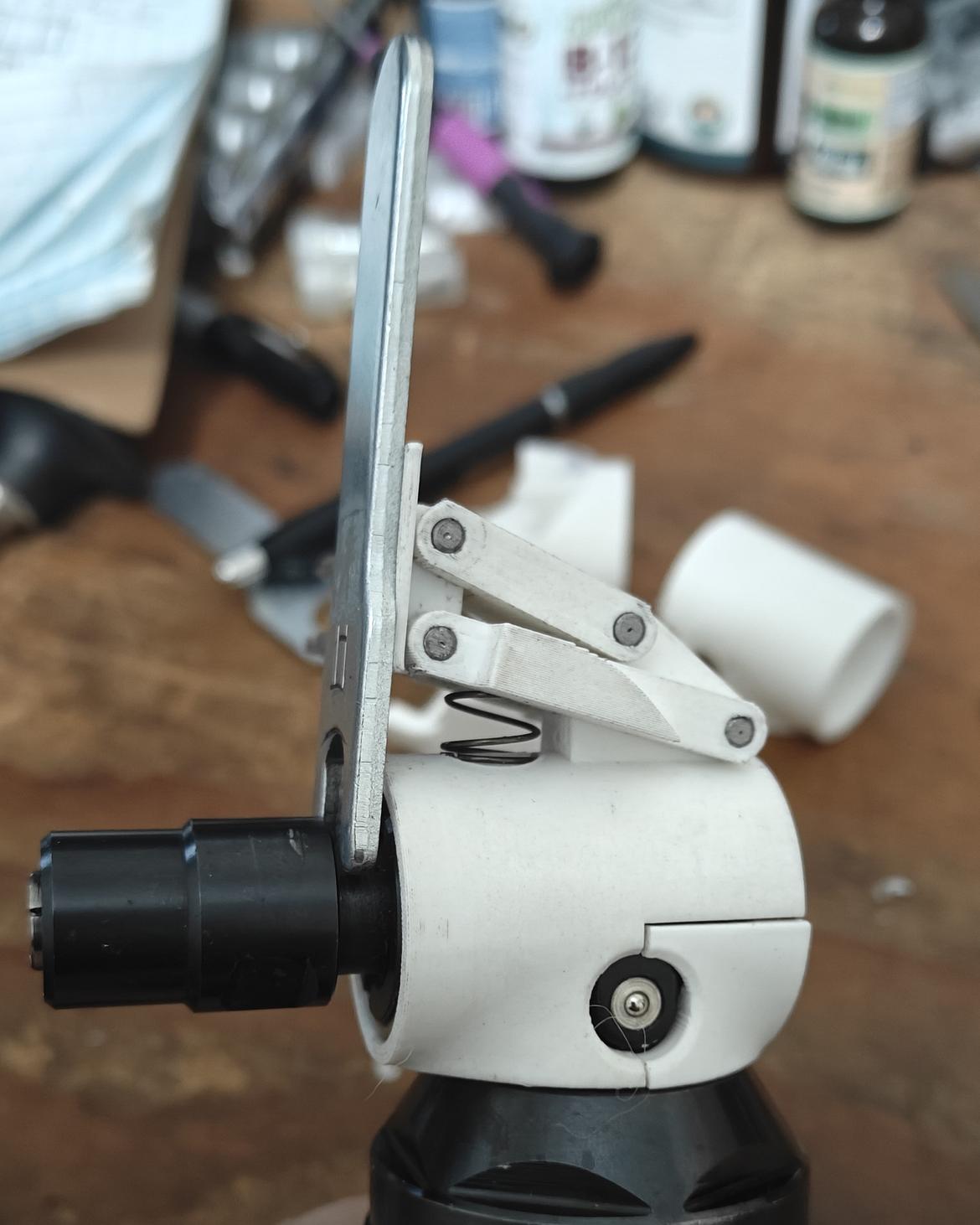
I took it as an opportunity to practice some texturing with the carbide burrs


I'm pretty happy with how close it looks to a cast iron surface finish


This is the radiator that was used for the I6 that was in the jeep.  It's the right size but the inlet and outlet are on the wrong sides for the 350.


This is where I started to run out of patience.  His claim that "a lot" of the build threads he read used the original driveshaft was baloney.  The nose of the water pump touches the radiator.

Annoying, but I can change the mounts to push the radiator forward so there's just enough space with a low profile electric fan.


I stripped, primed, and rewelded the mounts.


I thought this text was pretty clear.


However this is what showed up.

He was aware that the radiator was larger but didn't think think it mattered.

I could just barely squeeze the width in but the extra height meant that it ran into the steering box.  Either he needed to get the right sized radiator, or the engine needed to move back, or the grill needed to move forward.

I told him that we needed to get a either get the current driveshaft shortened or buy a new driveshaft and push the engine back 3".

He got pissy/argumentative and said that he couldn't justify the money for a new driveshaft or the time for the radiator to ship.  It turns out he had no idea how much a driveshaft cost and the deadline was artificial.


So I gave him what he wanted.


6 feet of sheet metal nicely bent and blended.

It looks twice as stupid in person.

Funnily enough the radiator still didn't fit (the bottom of the radiator hit the bumper mounts).  I was done putting in any effort so he sawzalled the bumper mounts and welded some extensions to push the grill forward another 4 inches.


It was a very frustrating way to spend 3 weeks and I've been burnt out on any fab work.

MNIMWIUTBAS
MNIMWIUTBAS New Reader
8/19/24 1:57 a.m.

These munchkins did help me work on the MG a bit

I need to put together a chassis table and finish up the design for mounting the front suspension. I'm starting to lean towards ditching the subframe (at least the stock one) but it's still up in the air.


(just for fun)

MNIMWIUTBAS
MNIMWIUTBAS New Reader
8/19/24 2:23 a.m.

In reply to NOHOME :

The guy with the MGB / Miata chassis swap on youtube never responded to my messages about how he did it, but he has a second video up where you can catch some glimpses of the interior.

I put a lot of thought into grafting in the front clip but I think building one from scratch could end up less work (famous last words).   Something like this build for a crazy v8 miata.

MNIMWIUTBAS
MNIMWIUTBAS New Reader
8/19/24 3:27 a.m.

In reply to Nukem :

Sorry, my links earlier in the thread expired.

This has a cleaned up blender file that you can export whatever you want from as well as just the suspension in .step and Fusion native formats

https://gofile.io/d/3Xu5c2

TurboFource
TurboFource Dork
8/19/24 8:31 a.m.

That GT350 sounds awesome!!!

Nukem
Nukem Reader
8/19/24 8:39 a.m.

In reply to MNIMWIUTBAS :

MVP right here.

This is looking more bonkers than I expected.


AngryCorvair (Forum Supporter)
AngryCorvair (Forum Supporter) MegaDork
8/19/24 9:42 a.m.

I like what's happening here. Except for the jeep clusterberkeley. If you want it done right...

DanielN
DanielN New Reader
10/18/24 7:49 p.m.

I'm pretty sure I know where that body CAD model came from, just a heads up it's not particularly accurate. I would recommend importing some far away images of the MG into your CAD program and confirming the areas you need for clearance like the hood etc. are close enough. When it comes to the underside I have some good scan data I can probably send.

On the other hand this looks set to be a real monster, best of luck on continuing to push through. Lots of heavily re-engineered MG's on here, it's a nice early, compact unibody platform and parts are so easy to get.

MGBGTMartin
MGBGTMartin New Reader
11/29/24 6:36 a.m.

In reply to enginenerd :

Hi Enginenerd, I am a UK based MGB owner busy installing a Ford focus ST170 engine (I think they were call an SVT in the states) mated to a ford type 9 5 speed gearbox. The engine and gearbox are in on custom engines mounts and I am in the process of clearancing the front crossmember. I can share my progress on here if everyone is interested!

I am just wondering where you got the 3D model used in this artical from? and is it readily available? Any info would be greatly appreciated. Thanks in advance

TurboFource
TurboFource Dork
11/29/24 7:07 a.m.
MGBGTMartin said:

In reply to enginenerd :

Hi Enginenerd, I am a UK based MGB owner busy installing a Ford focus ST170 engine (I think they were call an SVT in the states) mated to a ford type 9 5 speed gearbox. The engine and gearbox are in on custom engines mounts and I am in the process of clearancing the front crossmember. I can share my progress on here if everyone is interested!

I am just wondering where you got the 3D model used in this artical from? and is it readily available? Any info would be greatly appreciated. Thanks in advance

Of course we want you to share!

MNIMWIUTBAS
MNIMWIUTBAS New Reader
6/18/25 7:44 p.m.

Other project / Fun stuff I've been doing


I traded some fresh baked cookies to check out a sweet super puma with a really phenomenal paint (clear coated and polished).

They were in town to pick up the astronauts from the SpaceX capsule


We Painted my brother's truck.  getting all of the trim off took ages and we had a few hiccups but overall it came out great.  It was his first time doing body work and after some initial frustration he's gotten pretty capable at prep and paint.  We wet sanded the clear up to 1000 grit and is flatter than most SEMA cars.  gave it a 3 rounds of cut & buff then few coats of wax and it looks better than new.

We both agree it needs a ~2" lift but I haven't been able to convince him to paint the wheels bronze despite using every toxic manipulation tactic I know.  


We picked up a new compressor and set up a post cooler with an improved filtering setup.  The radiator still needs a fan but there's already and incredible temperature difference with just the passive cooling.

Cool air can't carry as much water so more of the water separates earlier in the system.  This means less water in your tank and less water in the output air.

Compressor -> Radiator -> Coalescing Filter w/ auto drain ->  Tank ->  Particulate Filter ->  Desiccant Filter w/ auto drain ->  Regulator -> Out

That setup was haphazardly assembled so we could get the truck painted, the radiator and coalescing filter are both going to get soft mounts to protect them from some of the vibration and the particulate/desiccant/regulator setup is going to get wall mounted.  I would like to separate the compressor unit from the tank and plumb the tank outside to free up some floorspace but this is working great for now.


I designed and 3d printed a bunch of organizers for the toolbox and it has been really handy.  Everything is magnetized to the drawer and the tool.  I think I'm going to bite the bullet and do a gridfinity setup for this in the future.


I was liked how this last one came out.


I've been working on a system for sockets based off of this guy's work https://www.printables.com/model/680228-tracktwist-socket-holder-organizer-34-12-38-14-dri

I improved the geometry of the prongs, ditched the threads for push clip retainers, and made everything printable without supports.  It needs a few more iterations before it's done.


I'm also working on a retrofit spindle lock for my favorite tool.


I got it working with a simple 2 joint setup but it's still finicky so I'm probably going to end up reverting to the 4 bar linkage.  


Oh, and I picked this thing up.  It's a slight upgrade from my gantry machines.

MNIMWIUTBAS
MNIMWIUTBAS New Reader
6/18/25 8:05 p.m.

MG updates

I tore down the original engine and found the culprit for the oil burn and low compression.


The head water passage leaked into cylinders 2 and 3.


2 and 3 were both 15% off from 1 and 4's compression.  The damage isn't too deep but it definitely needs some love from a machine shop.


I haven't cleaned off the surface of the head or the block but based on the few areas I indicated it may not need to get resurfaced in the event I feel like rebuilding it.

The internals were in good shape aside from some slight corrosion on the lifters and a few of the cam lobes.

It also looks like someone went at the #3 bearing with a claw hammer to get it installed.  No damage to the crank thankfully.

MNIMWIUTBAS
MNIMWIUTBAS New Reader
6/18/25 8:21 p.m.

I'm back on a v8 kick.  

In the interest of getting it running sometime this year I'm probably going to get it assembled with a short block hugger header and an x pipe as close to the collectors as I can get it.


My plans for the front end have evolved a bit.

+

=

I need to do some more math, cad, and headscratching but a bolt in front clip should be possible with some tie ins and reinforcement to the firewall area.

My pie in the sky idea is to have a setup where I can swap the cooling/engine/transmission out as a single unit by unbolting the purple section and the clutch master.

MNIMWIUTBAS
MNIMWIUTBAS New Reader
6/18/25 8:28 p.m.

In reply to DanielN :

Yeah, it's ripped from Forza by that Russian site.  It's been surprisingly close for the body panels (close as in +/- .75").  It's not getting used for any real measurements or fab work, just napkin sketching essentially.

MNIMWIUTBAS
MNIMWIUTBAS New Reader
6/20/25 5:46 a.m.

I roughed out the firewall cuts.


Now I need to find a T5 and build a frame table.

1 2 3

You'll need to log in to post.

Our Preferred Partners
hAT5b4308bjXWPh9b1iKRVJPNjIAp2Mjp2sLO7XHaogok4nhUgF74T8BNg1FYnwJ