Enbloc
Enbloc New Reader
5/25/22 4:48 p.m.


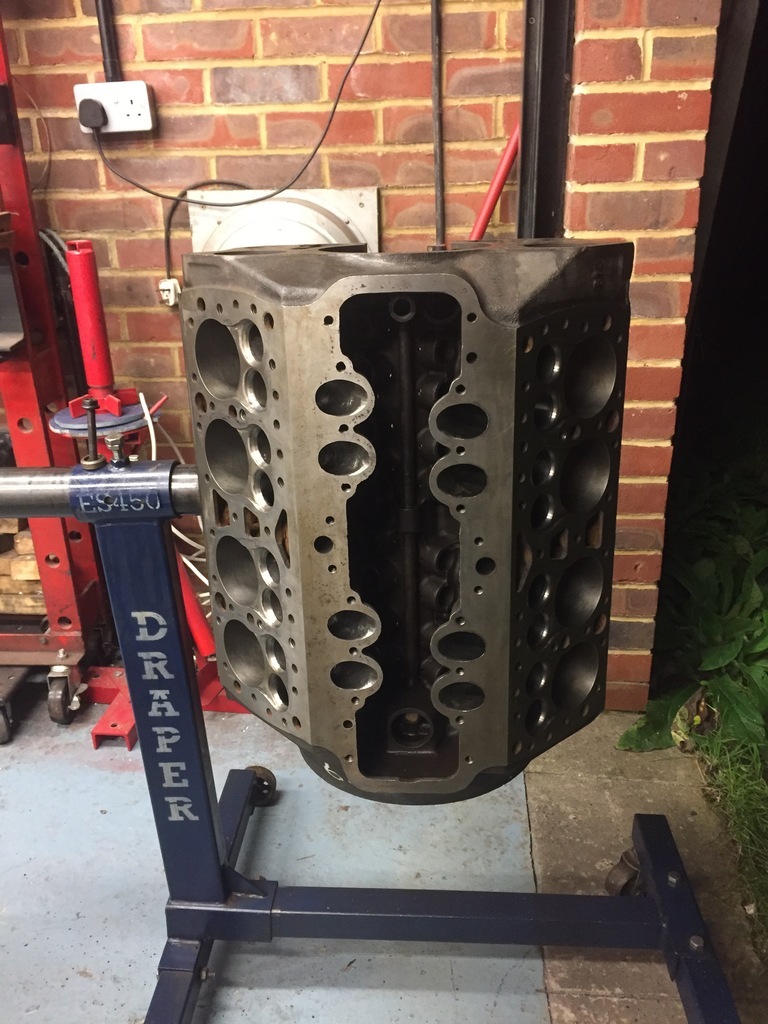
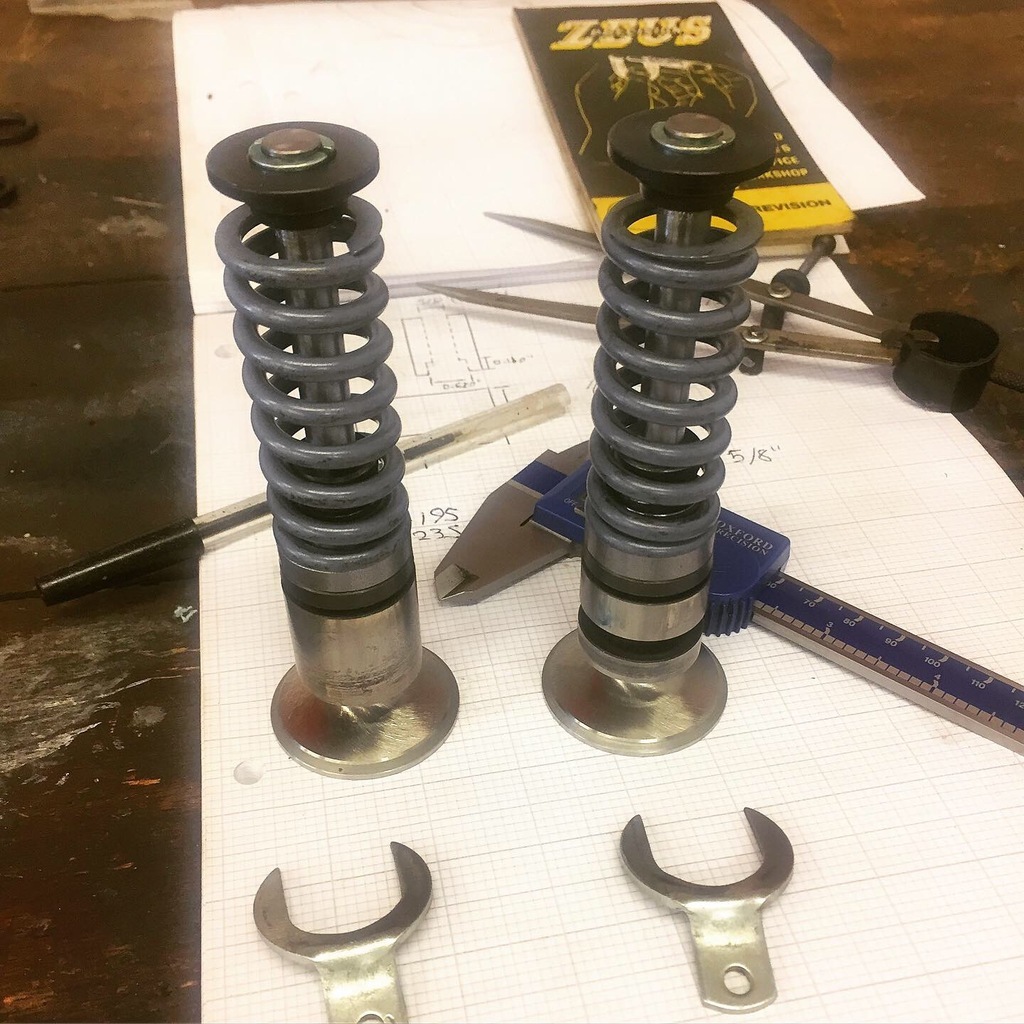
Let's start off on a high!

I'm a part time lurker that after some time on the dark side that is social media I've found myself gravitating back to forums because let's be honest there are only so many glamour shots that can hold your interest.

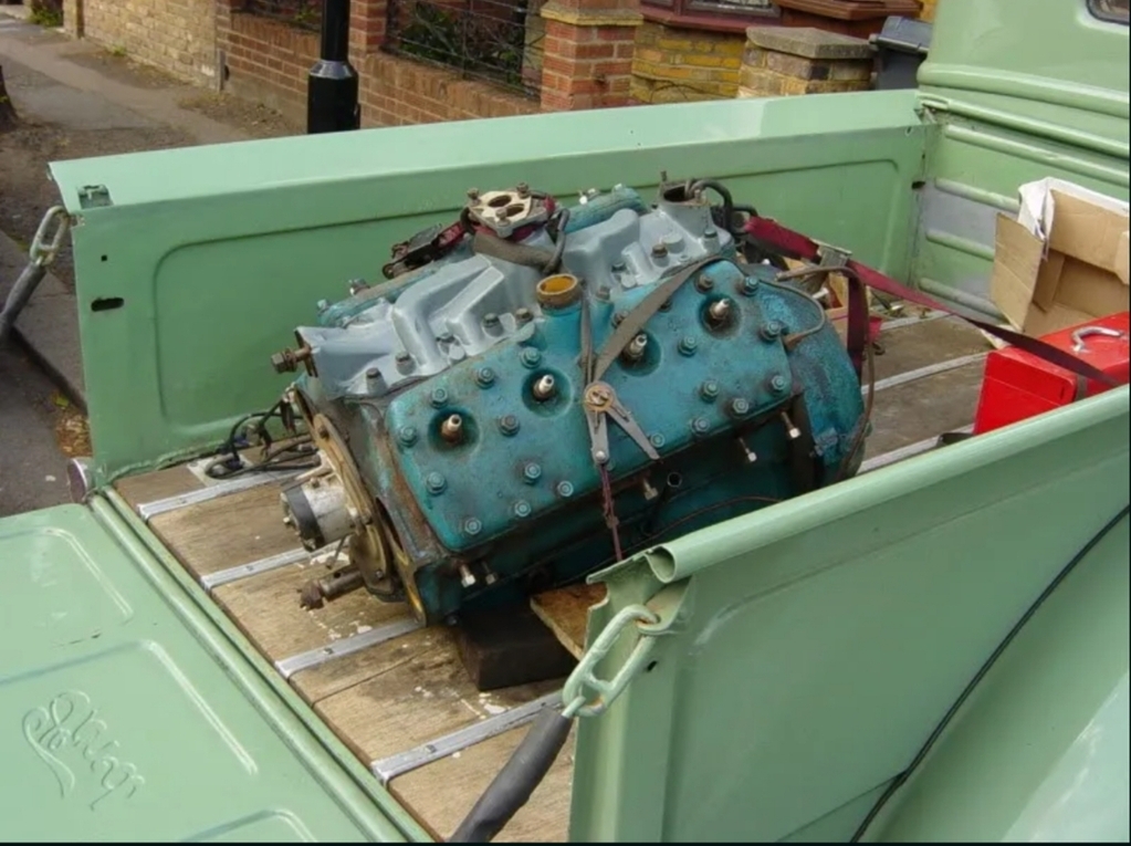
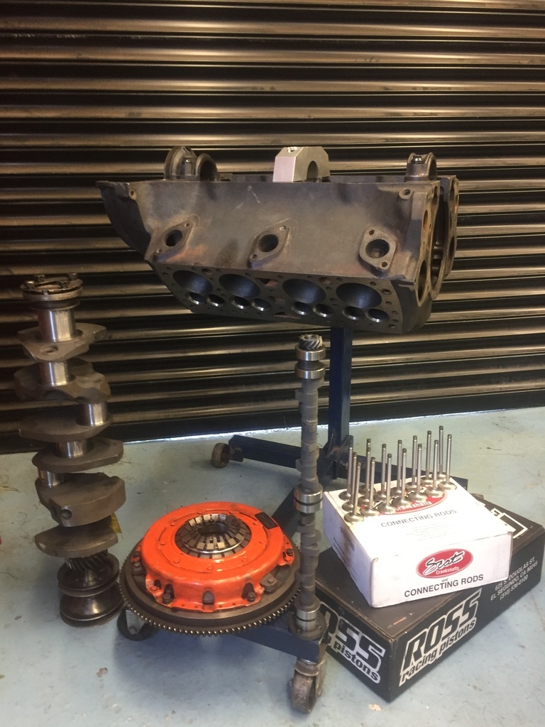
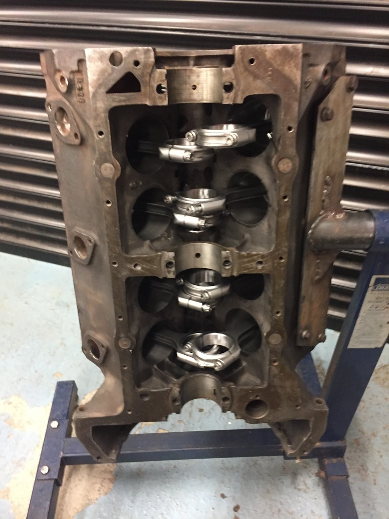
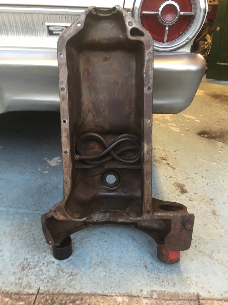
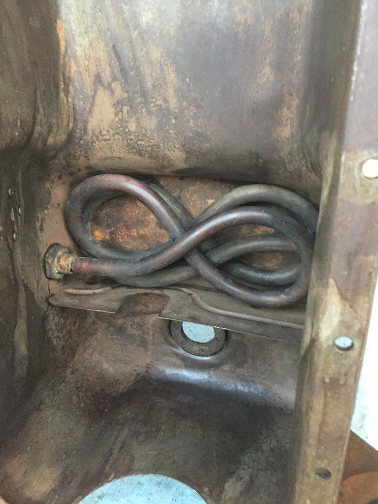
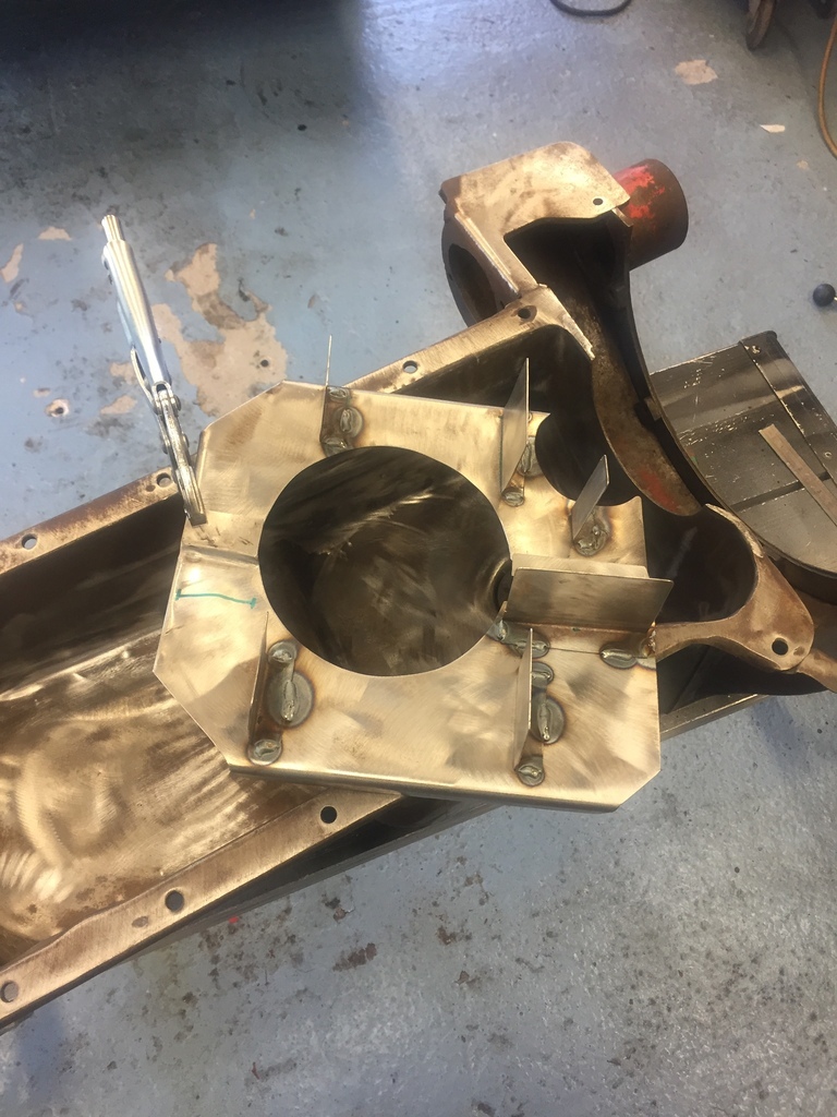
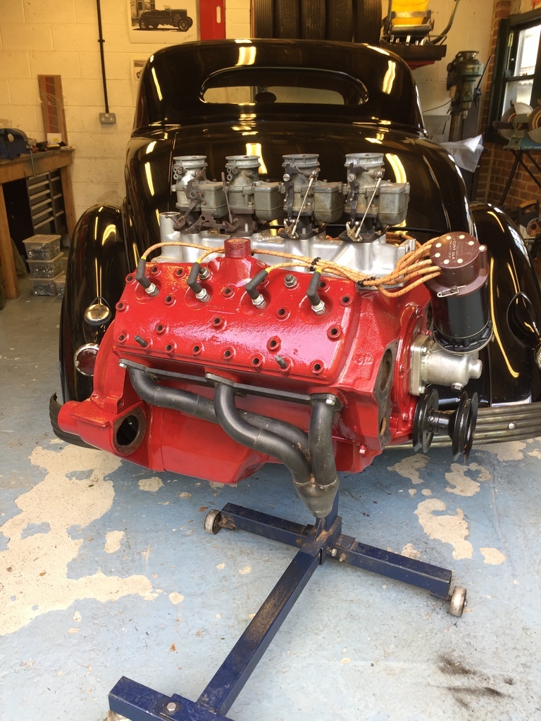
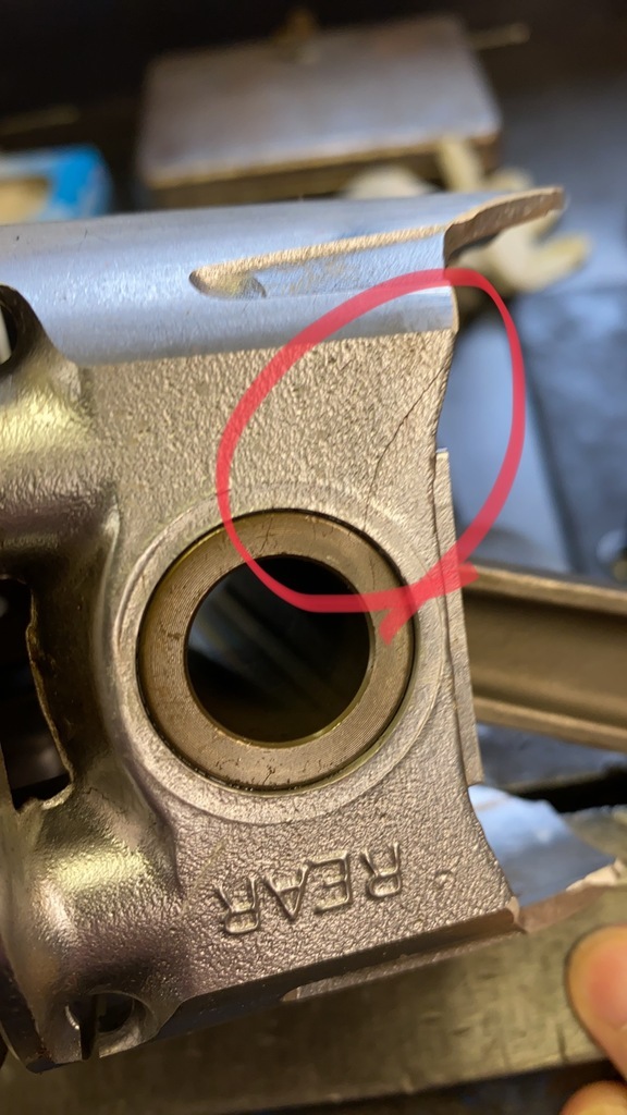
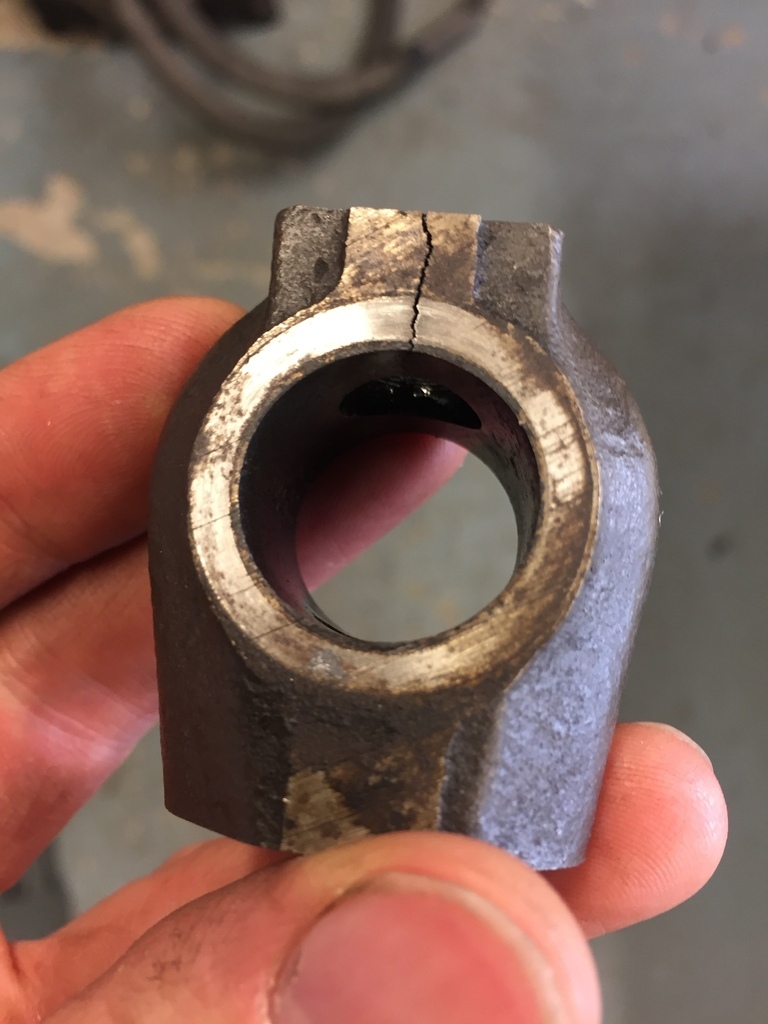
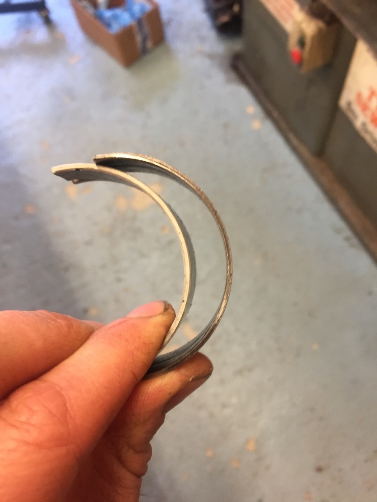
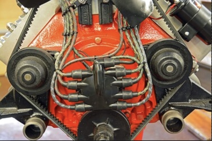
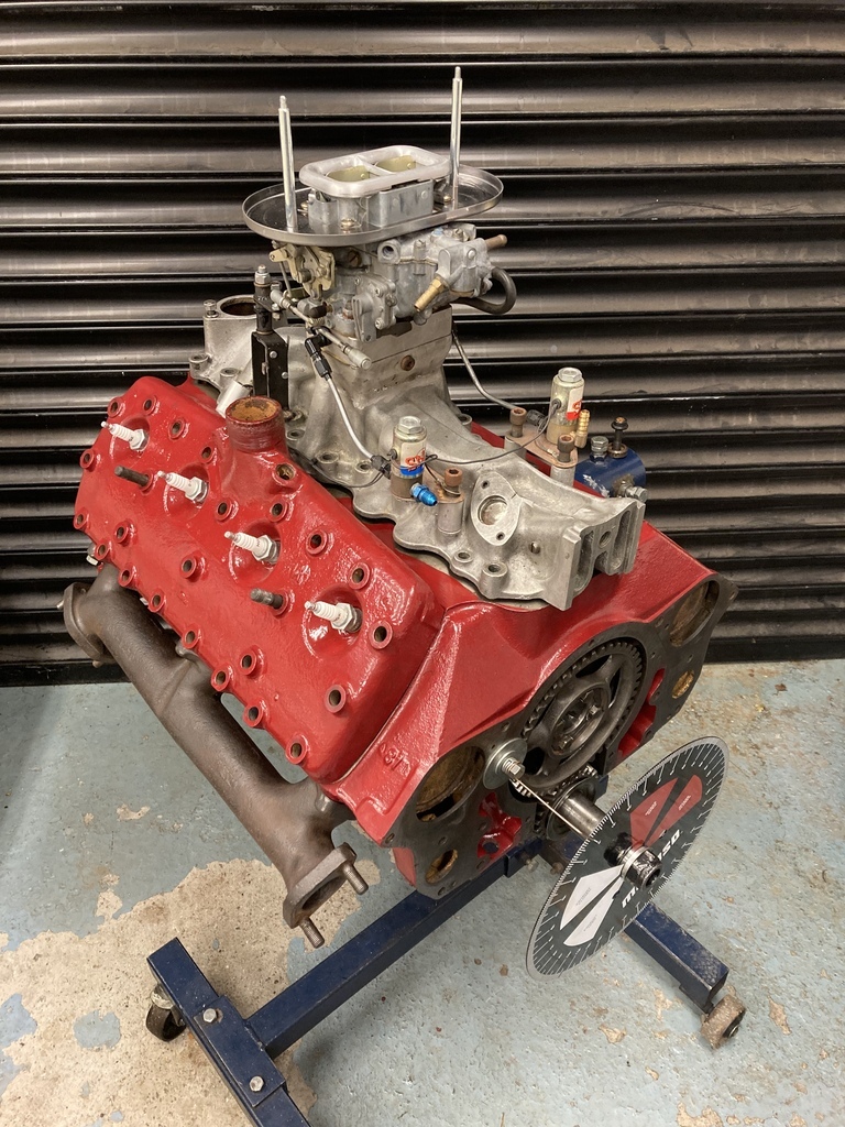
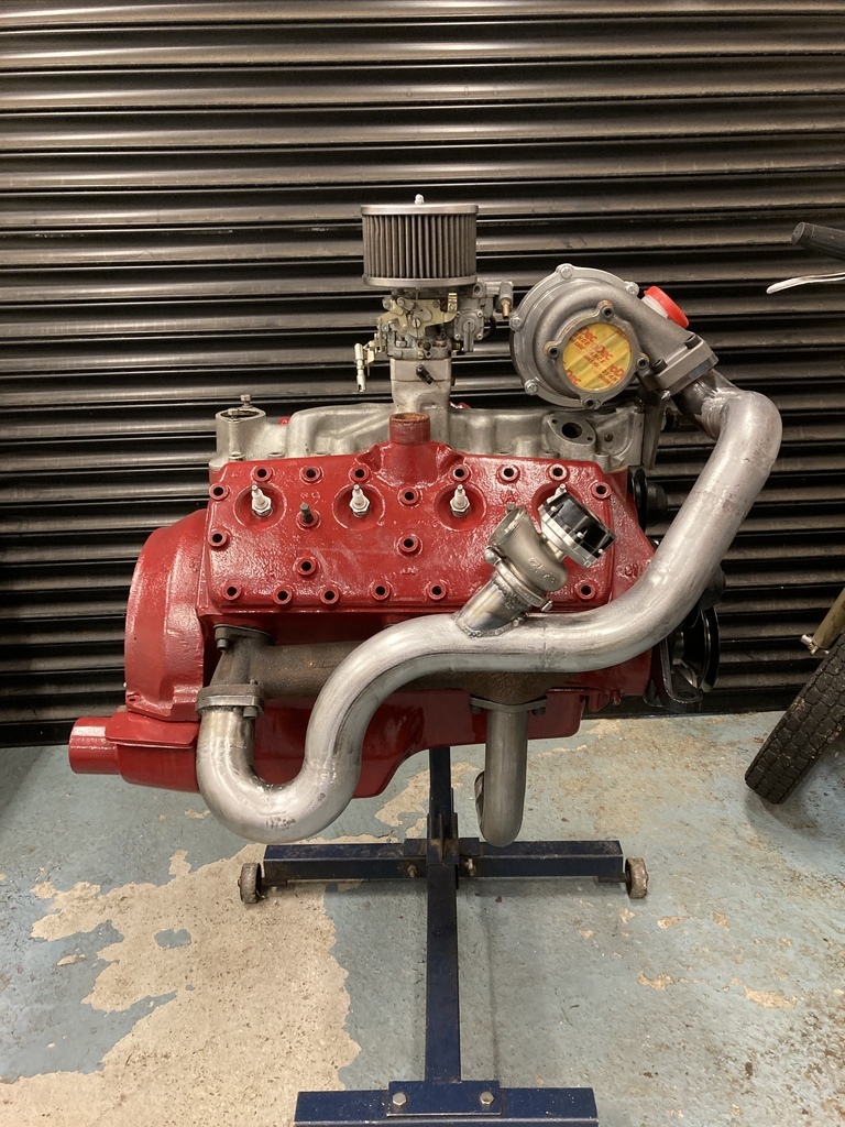
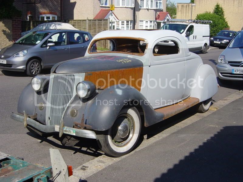
I thought my current distraction, what you see above, would be a good as thing as any to start a build thread and hopefully give something back.

Lets wind the clock back to 2009.
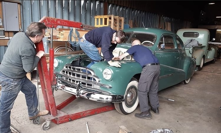
After a couple of Ford Model A's (I was dailying my first Model A at 19!) I got burnt out with them, sold it all and tried to buy a Porsche 356, as you do. Couldn't find the right 356, got impatient and bought this 1936 Ford 3W coupe instead. This was a full project it had no engine, gearbox, interior, floors etc. It needed everything.


I covered the full build of the car and what's left of the thread can be viewed here.

https://www.jalopyjournal.com/forum/threads/ooh-the-horror-my-36-coupe.378308/

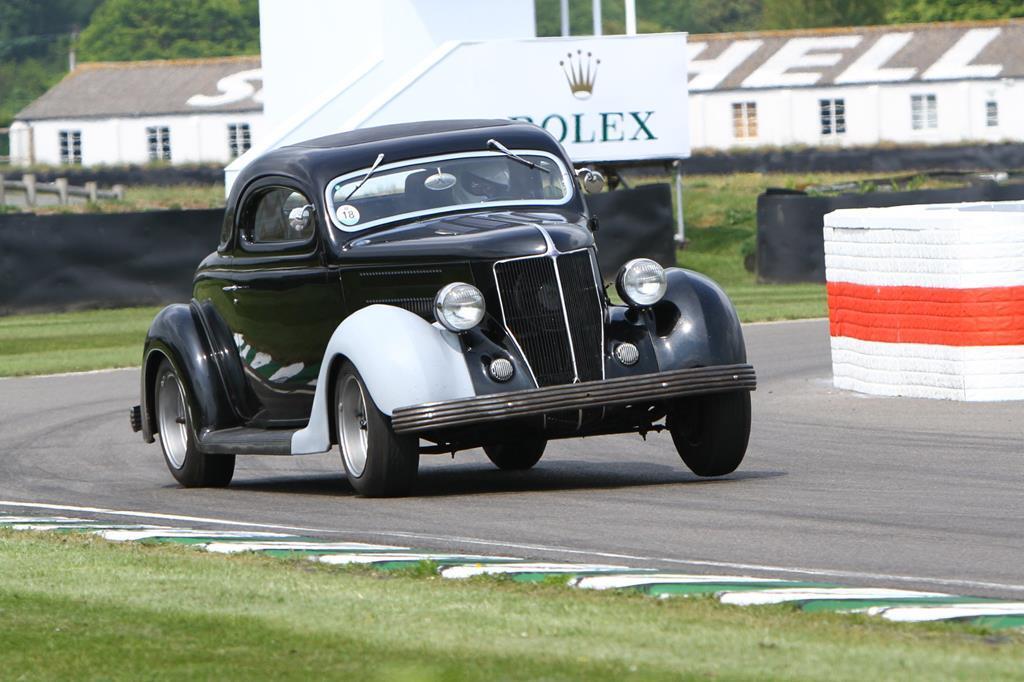
I did EVERYTHING in this car from shows, drag racing, dirt tracks, sprinting and hillclimbing. I've driven it through most of European. As far south as the Mediterranean Sea, over the Swiss Alps in East and as far north as Sweden. It's even lapped the Nurburgring!

It became and still is quite the all rounder I always wanted it to be.


What's all this rambling got to do with a turbo'd Flathead?

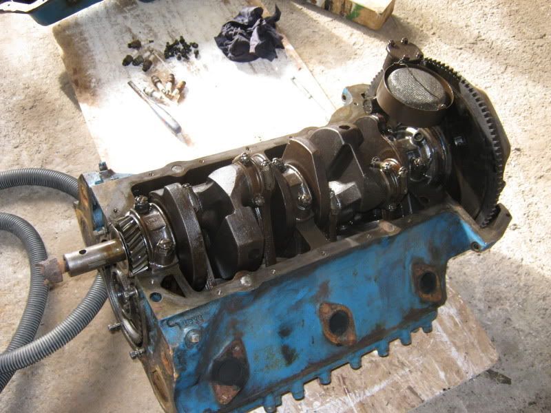
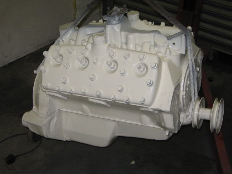
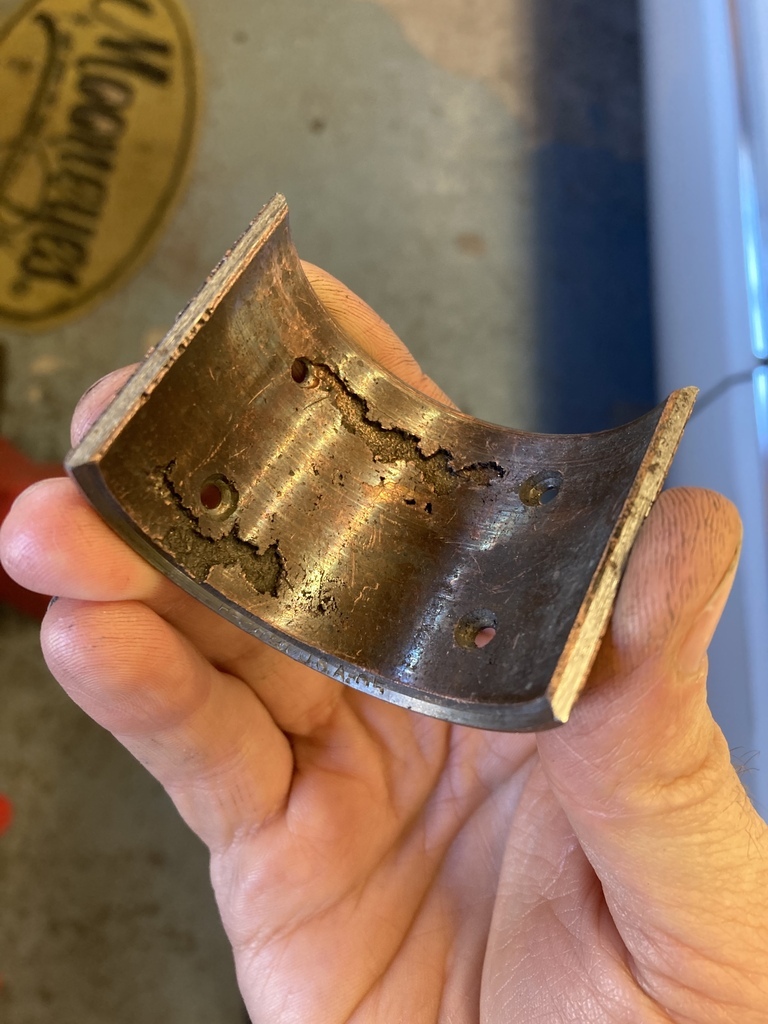
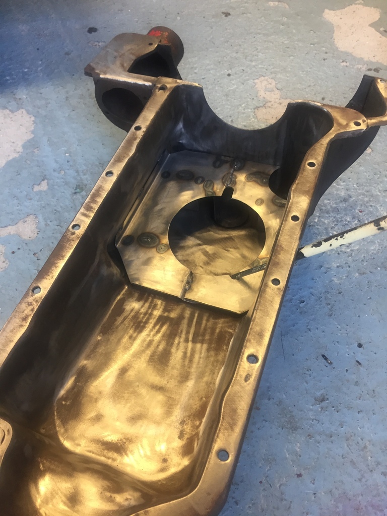
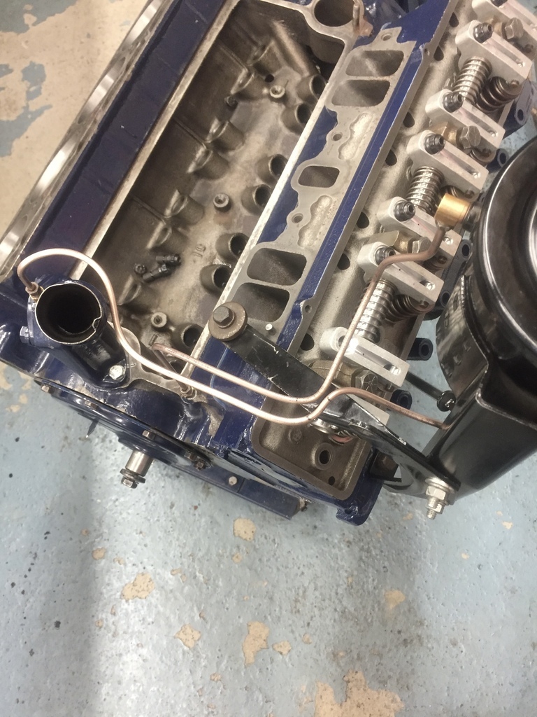
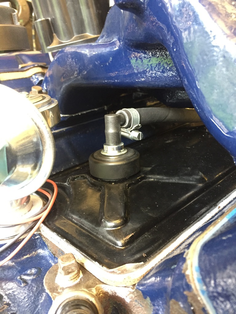
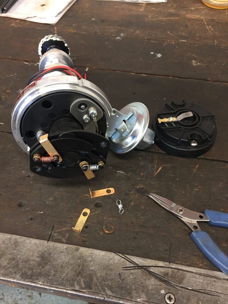
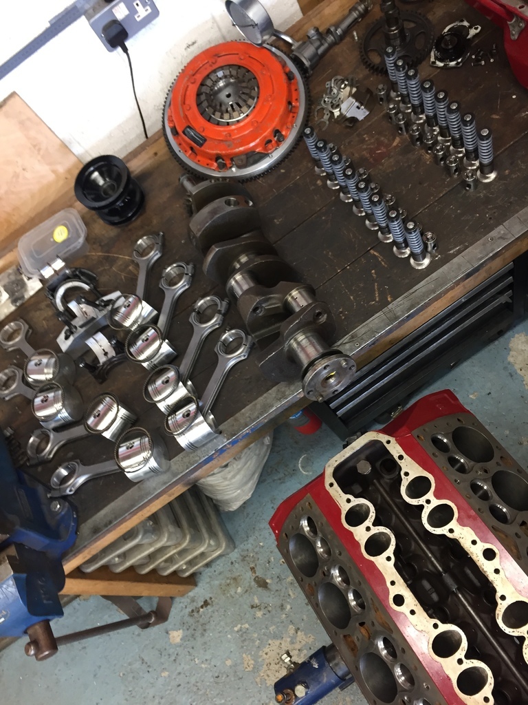
Alot of this action? abuse? happened with the power of a little small bore Flathead engine. Remember me starting with an engineless project? At the time I was looking for an Flatty and one came up on EBay for a few hundred ££. Take out, runner (Aren't they all!?).

Flatheads aren't particularly rare here but they don't grow on trees either. The days of a couple of hundread ££ are llooonggg gone now.

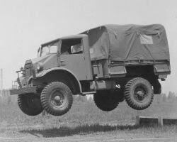
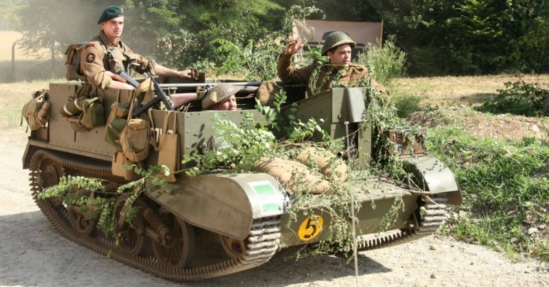
The story from the seller was that he had removed it from his '42 war time CMP (Canadian Military Pattern) truck because he'd fitted a big capacity French Flatty so he could run it on LPG! The story checked out because he took me out in the CMP truck with French motor and LPG. He also showed me his Flatty powered tracked Bren Gun Carrier and '41 Ford Woody staff car!

This is a CMP truck.


This is a Flatty powered Bren. Interesting fact about the Bren's is that they are steered with a steering wheel not levers or pedals and initial steering input tweaks the tracks so you can steer a sweeping curve. As more steering lock is applied it locks a track to be able to rotate on itself like a conventional track vehicle.


To be continued…

Enbloc
Enbloc New Reader
5/26/22 7:59 p.m.

Here is the day in '09 when I came back with the engine in a friends '41 Ford pickup. Flathead powered of course. It had the ancillaries robbed but most of that I wouldn't be using anyway.


Now the question of how much do you prod the bear?
Very little it turns out. I did pull the sump to make sure there was something actually inside the block and then hit it with the paint gun.


The project moved on and eventually it was time for the first start.
This old video shows me as a very gawky 26 y/o, somethings never change! 
In the video you can hear the starter solenoid jam and hear me give it a wack to unstick it. The same solenoid is still fitted today and still randomly jams on 12 years later!

The car got finished and put on the road and the engine did sterling service for years apart from a brief hiccup early on with a faulty thermostat that cooked a head gasket on one bank.
I started to notice that it was getting a little rattly and smokey so knew it time was limited. I remember the exact time its fate was sealed. I gave it a boot full on the local  bypass, looked in the rear view mirror and saw nothing but a cloud of blue smoke. Opps.
Shorty after that it was pulled and replaced with a built French Flathead waiting in the wings.

I certainly got my money's worth. This was the condition of the big ends when I pulled it apart. The bearing surface had long since left the building and was running on the copper backing which itself was breaking up! They all looked like this.


Pete. (l33t FS)
Pete. (l33t FS) MegaDork
5/26/22 8:57 p.m.

Waiting for more smiley

Stampie
Stampie MegaDork
5/26/22 9:24 p.m.

That flaty sounds good.

Enbloc
Enbloc New Reader
5/27/22 11:46 a.m.
Pete. (l33t FS) said:

Waiting for more smiley

Lots to come yet!

Enbloc
Enbloc New Reader
5/27/22 11:47 a.m.
Stampie said:

That flaty sounds good.

Thanks.

It was just a stocker with twin carbs and no exhaust connected up at that point.

Enbloc
Enbloc New Reader
5/27/22 1:32 p.m.

Some brief Flathead V8 history. This block is known as a 81A and it’s year range is roughly 1938-1945. It’s basically the crossover from the earlier 21 stud head 221ci(3.6L) to the later 24 stud head 239ci(3.9L). Its construction consists of the internal architecture of the early engine and the external architecture of the later motor.
Fundamentally not a bad engine they aren’t particularly desirable either.

With the engine being a small bore, small stroke crank my crazy plan, at this point, was to build a bullet proof, high rpm, screamer!
Now “screamer” is a relative term. A stock Flatty’s peak rpm is around 3500rpm and my French Flatty peaks at 5300rpm which is  pretty good going.

I have now found myself with a dead V8 and no real means to store it so I did the next best thing and let someone else store it for me by handing the heavy bits over to Royal Kustoms.
Even though the engine was knackered, the block which is the important bit seemed to be in excellent condition from a casual inspection. Only full crack testing would decide the fate of its future. It passed the crack testing with flying colours. Full steam ahead.

A time later this is what I got back from Royal Kustoms.
A rebored block taking 221ci out to 239ci. The maximum you can go on a small bore block. Reground crank, healthy Cam, larger Pro-Flo valves, aluminium flywheel, diaphragm clutch, forged rods and custom ordered forged pistons. Why custom pistons? Forged Flatty pistons are an off the shelf item but not when you’re at standard bore. Nobody is building standard bore Flattys anymore!


Some more magic was added to the block. Remember the bullet proof bottom end idea? The Flattys have 3 mains, yes 3, count ‘em. This isn’t as much of a problem that some will lead you to believe but when it does become an problem it’s usually the centre main that goes first.
Royal Kustoms created this solution. A billet steel, 4-bolt main cap to replace the factory cast, 2-bolt one. Belt and braces.


chandler
chandler UltimaDork
5/27/22 1:37 p.m.

Was just reading this on RR, good stuff 

Enbloc
Enbloc New Reader
5/31/22 12:25 p.m.

With the block back it was time to get on with more prep work. 
First was to relieve the deck face. The valves in a Flatty are sunk into the deck face in relation to the bore edge. What was realised in the depths of history was this ‘excess’ of material between valves and bore could be removed to create a significant increase in airflow. The same mod even went onto being incorporated into the block castings in the last generation French engines.

Stock engine


Relieved block.


The relieving itself can be achieved multiple different ways and the type of relief that is best will be argued over to the end of time.
I chose to do a simple full width, fixed depth relief at 0.100” thou (2.5mm).
But how to do it?
I had a mental note in my head of using a wood router! A router is basically a die grinder in a fixture, so with a decent carbide burr it can make quite the milling machine!
Nothing like frill of sending a carbibe burr into fresh bores. 

I’m certainly not reinventing the wheel here as I found this picture in the Peterson Archives from I guess the sixties.
Yes, I had the same expression on my face through the whole experience. 


It was at this point, 2017, that I lost interest in the whole thing mainly because I’d bought this…


There was a small amount of movement in this down time when my lovely partner got me this much wanted, surprise birthday gift, 4 carb/8 throttle original Edelbrock manifold because you know, REVS!


Enbloc
Enbloc New Reader
6/1/22 4:33 p.m.

So, roll on 18 months and I finally had enough of tripping over this thing in the garage. That and seeing the start of surface rust forming on the machined surfaces spurred me on to actually put it together.

First job was to get the block back on the engine stand. I decided to give it a very superficial port job. Enthusiasm was still lacking and attempting a porting job wasn’t really helping.
Over that hump it was given a good clean in readiness for some assembly.


I treated myself with this engine build to a piston ring filer. Wow! What a revaluation it was compared to hand filing. It took a fraction of the time, much cleaner finish and I still had skin left on my fingers at the end!


Remember the custom made standard bore pistons? 

This happened next…

The forged rods from Scat are to big to pass down anything but an oversize bore. 
Where to go from here? My initial idea was to feed the piston/rod assembly in from the bottom of the bores. This was a failure in two respects. First the underside of the block isn’t flat or square to the bore like the head side so the piston compressor doesn’t sit flat and the rings pop out as the pistons get knocked in and you kink an oil control ring… like I did…. curse word. The second issue is the the pistons won’t pass the 4 bores adjacent to the centre main because of the webbing.
Second idea was to disassemble the piston from the rod, push the piston down the bore as normal and push it far enough out the bottom of the bore to expose the piston pin but not so far that the rings spring out. Reconnect the piston to the rod and push the whole assembly back to the top of the bore again. Repeat X7.


Fiddly but it did work. Crank goes in as normal and pull each connecting rod up to its journal.

Before the crank went in though I had another change and decided the lightened factory flywheel that I was originally going to use and had all been balanced into the rotating assembly didn’t really fit with the “rev monster” ethos. I splashed out on an super lightweight SFI spec aluminium flywheel and of course had the rotating assembly balanced… Again.


Enbloc
Enbloc New Reader
6/5/22 3:23 p.m.

With a break in engine assembly, probably due to waiting on on a replacement piston ring pack from Ross (See above), I decided to address the sump issue.
Said sump issue was basically that I’d robbed it to go on the replacement French that was now in the car.

Luckily  I’d had the foresight to pick up a couple of Ford Pilot style sumps from a previous visit to the Bealieu Autojumble. I dug out the best one (Read the one that needed less cleaning) and then remembered what was lurking in the bottom.

What the…??


Fair play to whoever created this piece of copper pipe mastery, squeezed it into the bottom of sump, soldered the ends on and connected it all up. It was a utter pain to remove as well. It was in there tight.

And the million dollar question, heater or cooler?


Apart from filling the holes from removing the pipe work the main job was to build up some baffling around the oil pump pickup. Most Flatheads came with zero baffling of any kind. Way back when I starting hillclimbing this car/engine combo the lack of oil control never sat well with me. 
Again, way back, I built some simple baffling as a “something is better than nothing” stop gap. Well, it worked so well as I never suffered from any oiling issues after many years of competing that I just copied the design over to the replacement sump.


As mentioned the sumps origins are 50’s British. They are identical to the US sumps bar one difference, the starter motor mount.
In true British engineering tradition, you take a simple design that works and has been in production for 25 yrs and produced in its millions and you make it more complicated and not interchangeable with anything else!
The US stater motor is a simple round hole with two fixings. The British version has the same fixing points but the hole is just slightly smaller and out of round, #becauselucas.
All is not lost as you can simply enlarge the hole to US size. I turned up this MDF template ready for when the time comes.


Enbloc
Enbloc New Reader
6/8/22 9:37 a.m.

With the rotating assembly fitted it was time to move onto the valve train.
Of course things aren’t quite conventional.

The valve assembly is built up outside of the engine.


The complete assembly is then dropped into the valve guide bore in the block where the use of a tool affectionately called a pickling fork is needed. 
The forked end on the pickling fork slots into a groove in the valve guide which when levered against the opposing side of the valve chest allows you to pull the whole assembly down against the valve spring exposing another slot in the valve guide where a horse shoe clip is slid in with your fingers.
Simple right?
Well no. 
The whole process is like playing a game of Operation, upside down and without removing it from the box it came in! 
Add in an uprated valve spring and you’re now putting your full force on the pickling fork to hold the spring down, praying the fork doesn’t slip off and take your fingers with it.


Before all this some other jobs needed addressing first.
Because of the material previously taken out the port/bowl the guides now stuck up into the port.
This simply involved facing the top each guide until it was flush again.

As mentioned I had fitted aftermarket valve springs. There is now only one true performance spring available for the Flattys and that’s from Isky. It does makes spring choice somewhat easier.
The Isky springs are specified to have installed heights of 1.800”, 1.900” and 2.00” depending on desired seat pressure.
What I’ve never worked out , unless I’m missing something obvious, is when straight up installed these springs always measure out 0.375” (3/8”/10mm) too long.
What to do?
This is beyond  basic valve shims and stacking valve shims wouldn’t work either as  even though the guide is long enough to accommodate them after about 0.100” of shims the centre spring locator stops and the shims would just be rattling around under the spring.
What I did was turn up 16 spacers that were 1/2” long that slid over the original valve guides and then had an internal step turned in the I.D at the bottom to locate them on the original spring locator step.


Each valve assembly was fitted without the spacer. The spring height measured with internal calipers and the 1/2” long spacer was turned down in height to achieve a 2” installed spring height.
Repeat x15

Add the Schneider 284F (Race) cam and you get lift.

As a side note I collect licenced Pre-War Ford tools, which there are many.
This is a puller that is for removing the valve assemblies from the block. As you can imagine cast iron block and cast iron guide add time and moisture and they can become quite stuck.
With no real access from the backside this method is works well. The alternate is cutting wheel and BFH.

[img]ttps://img.retro-rides.org/i/v/4ever4/0f5d50d55180.jpg[/img] 


Professor_Brap (Forum Supporter)
Professor_Brap (Forum Supporter) UberDork
6/8/22 2:13 p.m.

Following for more cool flathead stuff. 

Enbloc
Enbloc New Reader
6/9/22 12:57 p.m.

With the bulk of the engine assembled enthusiasm was really starting to wane again for the whole thing. Jobs were being rushed and corners cut.
The unusual situation with this engine build was that it had no home and no end goal for its intended fitment. Usually you build an engine because of the need for one, whatever that need may be, that’s your drive to get it done to get it done. Not so with this.

Because I knew this engine was going to sit when finished I needed to start thinking of making attempts at sealing it up for storage. The sump dealt with the lower end, my lift plate made a great cover for the valve chest just leaving the heads to cover the bores.
I dug out the stock heads and plonked them on and yeh… they just floated off the deck faces. The over sized valves and valve lift caused major interference issues.
This was made more complicated by the heads themselves. Remember this is smallbore 81A engine . Because of the smaller capacity the 81A heads have scaled down combustion chambers to keep the compression consistent to the bore size.
The 81A heads are sometimes referred to as “cheater heads”. In some period race classes you would have to run factory heads so the use of these gained an instant compression ratio bump. Legal or not.
What to do? 
Rush it and cut corners of course by crudely hogging out the combustion chambers till the heads fit with the prospect of cleaning them up when the time comes. 


Quick mock up for the glamour shot, take it back apart, throw a cover on and push it under the bench.


The inlet did make it into living room and only recently got removed with a change around of the furniture.


Enbloc
Enbloc New Reader
6/10/22 3:58 p.m.

The engine went away summer ‘19 and didn’t see the light of day until end of ‘21, over 2 years in storage. Ouch!

I wasn’t idle in this time. I built 2 more engines among numerous other projects.
The first was the original 260ci Small Block Ford from the Falcon. It was original to the car and never been out or apart but ran like a top… Until I started sprinting in it and blew every oil seal and head gasket!
In my defence they were 55 yrs old and a little hard. 
A straight forward build bar the complications of being an early small bore (I see a theme here) which means that everything aftermarket SBF physically fits but doesn’t quite work. That and I got caught up with the start of the pandemic parts supply issues and ended up waiting months and months for a cam that never came and I ended up throwing in some weird Clevite Performer cam because it was the only one left in stock.


The second was my dads 1955 Cadillac 331ci in his 1948 Pontiac.


What a saga that was as I will explain, the thread title does say tangents.
The engine was a rebuilt take out from a Caddy that had got a SBC conversion in the States.
It ran lovely for about a thousand miles and then started getting a little smokey, then a lot smokey.
On pulling the heads it was found that multiple cylinders had 1” wide, 1/8” deep grooves running the full length of the bores.
Why?
The wrists pins had come lose in the rods and made their into the cylinders walls.
The Caddy motor has push fit wrist pins. To do this properly the rods little end is heated in a special oven that expands the rod end enough that the pin drops through and when cooled the little end returns to its original size tightly gripping the pin.
What cowboys do is take a gas torch to the rod, over heat it and  over expand it. It then doesn’t return to its correct size when cooled.
The rod is scrap, the wrist pin comes adrift and  takes the block with it.

The block was ‘saved’ with 8 (!) sleeves taking it back to standard bore, a replacement set of used rods from the States and a freshen up had it back running again for the next few years.
Then there was a series of unfortunate events.
Firs,  it blew a core plug at about 90 mph on Pendine Sands without the driver realising and the engine went nuclear.


Then some spirited driving at Prescott caused a “knocking” sound which went away but didn’t as a few months later the car was recovered off the M11 with a full blown rod knock.

Rebuild 2.

Here’s what was found on strip down.

Cracked pistons probably due to the overheating.

Cracked rocker shaft stands.


Pounded to oblivion big end shells.


Trashed crank journal.


The crank was beyond economic repair. The rod only showed fretting, possible that it was salvageable but would you want to? Pistons were scrap and the bores showed scuffing from a partial seizure.

Enbloc
Enbloc New Reader
6/12/22 1:47 p.m.

To continue this rather long tangent…

The scuffed bores in the block were salvageable with a hone and cam also and that was about it from the short block. 

Where do you find a complete rotating assembly for a mid 50’s Caddy engine?
You dig deep into the memory banks of a vague recollection of a for sale ad that may have had what you needed.
A quick search and find said advert from 3 years previous and it’s all still available. Result!

Beggars can’t be choosers and even though the replacement crank was more than usable the locating dowel hole  in the crank flange had been gacked by I assume someone in the past attempting to drill it out (why?) instead of just knocking it out from the back.
Managed to save it by using the flex plate adapter as a guide to enlarge the oval hole and then turn a stepped dowel back to standard size.


On to the oil pump. 
Suspicion was starting to rise at this point with the oiling system having issues and being the cause of the failure especially as the oiling system is seen as a weak point on this engine family.

The stock oil pump is this thing.


What’s going on here is a conventional oil pump with a secondary vane pump piggy backed on.
The secondary pump is a vacuum pump. It’s only job is supply vacuum to the windscreen wipers!
The crazy situation is the two pumps are linked internally so when the vacuum side starts going wonky, as it surely will, the oil pump starts pumping air not oil.  
Strike 1.

Luckily Cadillac saw the error of their ways and in 1959 there was a cross over of oil pumps which meant you have an early style pump without the vacuum side that retro fits into the earlier block.

Another small issue found.
There should be a felt seal from pump pickup to pump inlet. If it’s missing it can again, suck air.
It was missing.
Strike 2.


The short block had all the oil way core plugs knocked out for cleaning and drilled and tapped for threaded plugs and of course new pistons and bearings and ARP hardware for good measure.
Short block went together and the cam degreed perfect which made a nice change.


Enbloc
Enbloc New Reader
6/15/22 6:20 a.m.

Moving onto the heads.

The heads had some new SS valves and valve springs at them at some point.
Problem was the valve seats were tired, the valve guides were worn and the valve springs were missing their internal dampers as they didn’t work with the OE spring retainers.

With the heads stripped of course they got the ports cleaned up and port matched.


The OE spring retainers had this metal umbrella arrangement that acted as a basic valve guide seal or oil deflector.
This is primitive stuff, doesn’t work very well and as already mentioned created issues with the replacement valve springs.
I couldn’t see a reason why their removal wouldn’t be an issue, so off they came.
I initially tried to face them off in the lathe but the umbrella portion was so thin they just collapsed in the chuck.
The angry wheel then made short work removing them but it took some time carefully grinding them flat and to within a couple of thou of each in width.


The springs could now be mocked up and measured for height. They were all with in 0.010” of each other which is good going and shows these engines were built to tight tolerances from the factory.


A valve guide seal was now needed and luckily the guides were the right diameter for a SBC/SBF modern style Viton seal to slide right on… but… the extra height of the seal on the guide meant there was naff all valve lift before the retainer ran into seal.
The valve guides are quite long from standard so it wasn’t a problem to remove the 0.250” (1/4”) needed to give enough clearance for the valve lift.


The heads were sent off to the machine shop to get new seats, valve guide liners and the guides machined down for the seals.

The rest of the valvetrain was a bit of a mess.
The valvetrain is non-adjustable which is fairly common for US V8’s. This is fine if you’re using all stock components, but change one thing, in this case the cam, and the whole valvetrain geometry goes to curse word.
First job was to find some adjustable rocker arms. 
They were available in period but are now rare. Rockers from other engines of the period like Studebaker apparently fit and are adjustable but it’s all hearsay and rumour and again hard to find. Then I was put onto a company called Harland & Sharp in the US who apparently still made them. I rang them, they would make them to order and would be with me in 4-5 weeks. Yay.


On stripping the rocker assemblies more issues were found. Two stands were cracked which I managed to get replacements for and the rocker shafts were worn probably due to the various sludged up oil holes.
Got the new parts and went to assemble and found another cracked stand and a mis-matched stand in the set as well because there are 3 different styles and one must have been changed out before in the distant past.
Annoyed that I had been halted on the assembly for the second time I bought another pair of used assemblies so I wouldn’t be caught out again with a lack of spares!
So, 48 rockers, 16 rocker stands and 6 shafts later I finally had two usable rocker assemblies.


Enbloc
Enbloc New Reader
6/20/22 6:03 a.m.

With the heads assembled and mocked up on the block it was onto measuring the push rod length and setting the rocker sweep across the valve tip.
These engines have a long push rod at nearly 8 1/2” long. The longest adjustable push rod available for setting up is is just over 8 1/2”. Lucky.


Then things didn’t quite go to the plan. 
What I’m trying to achieve is the optimum movement of the rocker roller across the tip of the valve. The reasons for this are to achieve  the least amount of lost motion and to locate the movement as close to centre as possible to stop excessive side loads on the valve stem which prematurely wears the valve guides. In extreme cases it’s even possible to roll the rocker right off the edge of the valve tip.
To test you simply engineer blue the valve tip and cycle the valvetrain a couple of times and then inspect and measure the sweep that shows in the blue.
What you want is a central sweep that is no more than 0.050” in width.


This is the best I could get no matter what I did. Off centre and around 0.100” width.
I changed the pushrod length changed +/-. I tried shimming the rocker stands up. I even made caps for the valve stems out of shim stock to change the valve length to no avail.

It seemed to me that there was a fundamental design issue going on and that the real problem was that the whole rocker assembly was in the wrong place i.e it needed shoving back.
Myth and lore with these engines is they have a habit of breaking rocker shafts in high stress (racing) applications. I can believe it after going through this.
Its not unknown to slot mounting holes in rocker assemblies to be able move stuff around but that was a no go with this as the rocker assemblies are bolted down and oiled via the head bolts. Slotting the stands would lose oiling to the rockers and create a pressure loss in the oil system.

What to do?

Nothing!

It is what is. It’s not a race engine. It’s going in a road car with a slush box. It might not be great but it’s not terrible either. Sometimes you just have to accept and move on and it’s probably better now than it’s ever been.

On to the finishing touches. 
The engine comes with a rudimentary sump baffle that bolts to the block. I simply added some extra baffles to contain the forward and back movement of oil.
Also made a new dipstick tube to replace the broken, bodged up one that was on it.


An oil filter wasn’t standard but you could have a bolt-on bypass filter fitted by the Dealer.
This engine had the filter fitted  but the oil lines were a mess with most of the fittings rounded off.

[img src="https://img.retro-rides.org/i/v/4ever4/0b4914ac32e9.jpg" style="max-width:100%;"] 

I couldn’t live with this so I replaced the fittings and remade the lines.


Converted the road draft breather system (rubbish) to PCV instead.


The original dizzy got canned and a brand new Pertronix billet one with igniter II and fully adjustable ignition got fitted instead.
But before it went in I changed the stops and advance springs from the short,  lazy curve that aftermarket dizzy’s always seem to evidently come with.


One final job before first start was to make a oil priming tool as funny enough they’re not available for these engines.

After having this engine so long I was determined for it go back in and be started.


We blitzed it one Saturday and done…


Floating Doc (Forum Supporter)
Floating Doc (Forum Supporter) PowerDork
6/20/22 9:47 a.m.

Shame on me.

assumed that the title of this thread, while highly appropriate to the subject, dealt with opposed/flat engines such as Subaru, air cooled Volkswagens, or Porsche. My most recent and brief episode of Subaru ownership cured me of any interest in them. 
 

I was trying to determine what country you are in. The conversation in the video of first start of the original flatty put that to rest. 

Fascinating thread, both for the look at the post war hot rod engines and glimpses of the British events (more of that would be welcome).  Eagerly awaiting more!

Enbloc
Enbloc New Reader
6/20/22 11:43 a.m.
Floating Doc (Forum Supporter) said:

Shame on me.

assumed that the title of this thread, while highly appropriate to the subject, dealt with opposed/flat engines such as Subaru, air cooled Volkswagens, or Porsche. My most recent and brief episode of Subaru ownership cured me of any interest in them. 
 

I was trying to determine what country you are in. The conversation in the video of first start of the original flatty put that to rest. 

Fascinating thread, both for the look at the post war hot rod engines and glimpses of the British events (more of that would be welcome).  Eagerly awaiting more!

Thanks for the feedback. Much appreciated. 

Yes, I'm in Britain, London suburbs to be exact. I tried to convey that in some of the  earlier posts because US parts available can play a big part in decision making and why I sometimes drift in odd directions to normal practice!

Interesting take on the thread subject line. It never occured to me the connection to Flat 4's! 


Enbloc
Enbloc New Reader
6/22/22 8:40 a.m.

After years of building NA motors I got a real hankering to build something with forced induction.
The obvious choice would have been a roots style blower sitting atop with everything available to bolt one on and go but I’d been soaking up the turbo revolution for years and wanted some of that.

Then I got to thinking about that built Flatty that I had abandoned under the workbench for over 2 yrs. Forged pistons, check. Billet rods, check. Strengthened bottom end, check.
Add onto the fact that I knew I had to take it apart because it wasn’t assembled very well the first time meant it would be the perfect opportunity to open up the ring gaps for boost.

Apart it came, which was a joy because it was clean and fresh and not the usual seized ball of oil and dirt.


I found a few mistakes taking it apart, nothing major, just poor attention to detail generally.
I was feeling better knowing it was worth the effort so far of taking it all to bits again and then when I had it back to a bare block I inspected the ports.
I don’t know what I was doing the first time but what  I did do was pathetic!
I then spent multiple hours a day, for the next 2 weeks with a die grinder until I lost feeling in both my hands and/or soul.
When all the dirty work was done and the oil gallery and core plugs removed I hit it with the jet wash for a thorough cleaning for re-assembly.
With jet wash in hand I had a play blowing water down the inlet and exhaust ports and even though this has no scientific value what so ever it does give some interesting visuals and food for thought in other areas.


And together it went.


Back to the piston fitting fiasco, again.
If you remember from previous ramblings the aftermarket connecting rods are to wide to fit down the bores so the piston/rods have to be separated, fitted  separately and awkwardly assembled in the crank case.
I wasn’t going through that again.
6 piston/rod assemblies would fit from the bottom (without rings) and the two middle ones wouldn’t because the piston skirt kissed the centre main webbing.
Having a closer look at the interference it was so minimal. I reckon you could have tapped the piston past if you was so inclined.
Out with die grinder and quick lick in the appropriate area had all the pistons able to drop in from the bottom for the first time.
This then allowed me to assemble the piston/rods as normal, push the piston out the top of the bore enough to expose the ring lands, rings fitted in situ and the ring compressor used as normal to push it all back into the bore.
Much easier.
Obviously remembering that this all has to be done before the crank goes in otherwise a lot of anger and swearing will be expressed.


I needed a way to be able to rotate the crank with the degree wheel  in place so I knocked up this adapter that bolts onto the crank flange using the factory flywheel bolts.


Keith Tanner
Keith Tanner MegaDork
6/22/22 10:09 a.m.

This is a great read. I don't know anything about flatheads so it's been quite educational. Looking forward to more!

Enbloc
Enbloc New Reader
6/25/22 3:22 p.m.

Flatheads from the factory have no external visual means of timing the engine. The original “crab style” dizzy can only go on one way and has a limited range of timing adjustment.

Stock crab style distributor.


I’ve found a simple timing indicator with one of the front timing cover bolts.
The centre of the bottom front cover fixing bolt head lines up perfect with the outer edge of the front pulley.
I simply centre drill the bolt head for a short length of rod that has a sharp point ground onto it and then epoxy the ground point into the drilled bolt.
After finding true TDC with the use of a dial indicator on no.1 cylinder, I simply mark the pulley where the point falls.
To finish I usually cut a small slot in the pulley and fill with white paint.


With True TDC found I can then move onto degreeing the cam.

My cam degreed 5 degrees advance from the cam card spec. 1 or 2 degrees I can swallow but 5 is way out.
Frustratingly, this is common scenario on aftermarket Flathead cams with no means of being able to adjust.
If it was SBC/SBF there would 10 different ways to adjust and correct.
What to do?
One of the options on small block Chevys are offset cam dowel bushes. Sold as kits, easily available and relatively cheap I purchased a set.
With the bushes in hand I took the original cam timing gear and drilled the googly hole bigger to except the dowel bush and the other three mounting holes got slotted on a rotary table.
To finish, one of the original mounting bolts had the head removed and the shank turned down to effectively make a screw in dowel to fit the centre hole of the bush.
Voila! 
I now have a fully adjustable cam gear simply by swapping out the offset bushes.


Enbloc
Enbloc New Reader
7/2/22 5:41 p.m.

The valvetrain was refitted from the previous build unaltered.
The valve springs were fitted with an installed height of 1.900” which was  in the middle of the Isky Cams recommendation.
The first time round I used internal callipers to measure the spring height. Not terrible but not the most accurate either.
You may of noticed in previous photos of a valve spring micrometer, which I had obtained since the first build.
I tried the micrometer on the first valve and it was 0.060” over on what it should have been. The second 0.060”, the third 0.060” etc etc!
Ok, they are all out but all out by the same amount.
This is well within shimming so I ordered 32 0.030” shims.
Remember the 3/8” spring spacers?
Yep, the shims didn’t fit over the shoulder of the spacer. 

Some time later…


That brings things full circle.

Next step, turbo.
Where do I even start?
No knowledge of turbo sizing, no experience from others, can’t read boost maps.
What I did know was I wanted to start with cheap Chinese turbo. I didn’t want to throw a load of money at a genuine Garret or other for something that might never see the of day at this point.
At around this time Richard Holdener posted a video on YouTube where he fitted a Chinese GT3582 Garret copy on a 3.0 V6 and was very complimentary to the sizing/combo.
At a guess I’d say 3.0 V6 is probably fairly well matched to a 3.9 sidevalve V8 in breathing capacity and power output.

There we are, £145 of your finest EBay Wuhan Whirly Boi.


Moving onto the inlet. 
I had in stock a factory inlet that had been modified for a Weber 38 and a near new Weber 38 jetted for a Flathead. Initial thoughts were for a blow thru set-up that must have been done a X100 with a Weber so the info must already be out there, right?

The whole Weber thing came about sometime ago when I was competing regularly on the hills with the Class Z Flatheads.
I had the standard dual Stromberg 97’s which were fine but wanted more.
The brief was,
- Replace the complexity of dual carbs with a single, large cfm carb.
- Move away from the basic 1930’s technology carburettors to a more modern, more tunable carb.
- Gain MPG with a single, more sophisticated carburettor.

I got an old factory, aluminium, 4 bolt carb, dual plane manifold off the scrap pile that a friend then modified for me by turning it into a Weber bolt pattern, single plane design.


But there was a sting in the tail.

Competing with the coupe against the roadsters always had me at a massive disadvantage as I had the biggest, heaviest car and the smallest engine (Great combo).
I always felt my biggest time loss was in initial acceleration wether that be start line or exiting corners.
My down and dirty idea was to hit it with a small (25-50hp) shot of nitrous oxide on full throttle which would give that much needed boost at the right moment.

Nitrous plates aren’t available for Weber 38’s, funny enough. The same friend that did the manifold conversion also made me this one off nitrous plate that also doubled as a 1” carb spacer for linkage clearance.


With the hard part done it was plumbed and wired.

At this point I had an epiphany. This idea is genius, why has nobody already thought of it?
I picked up the Motorsort UK blue book and there it was in black and white, “no oxygent’s”.

Bo**ocks.

I was so far into it at this point that I decided to continue and had everything ready, I just needed the N2O.
I tried and tried and tried. I couldn’t get gas anywhere even vaguely local. The closest place was like a 100+ mile round trip which at this point I said another bo**ocks to it all and binned the whole idea.


The Weber set-up did live on and worked well. I got it dialled in and headed to the rolling road were it produced the exact same bhp to the dual Strombergs!
The Strombergs produced a better torque curve, so overall the dual Strombergs were a better package.
Oh, and the Weber did the exact same MPG as the Strombergs as well.

I think this is the only picture I have that shows it was ever a thing.


You'll need to log in to post.

Our Preferred Partners
3OiSvXoBibwHsmLjZAfXx03P5wS1Al8eflHWwCeG4oNNOIEkdik8EBwaefed6F4u