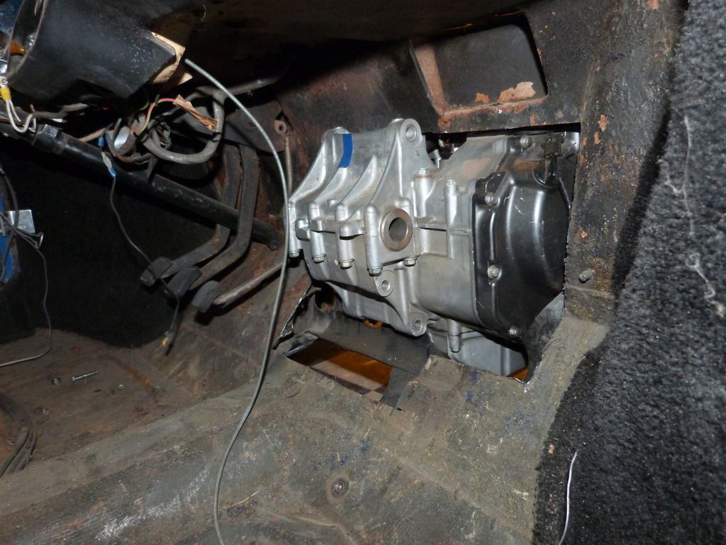
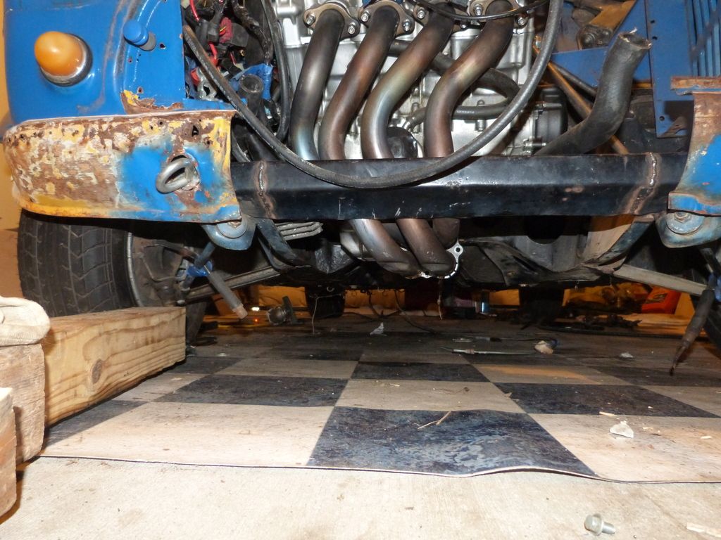
This is Miss Jane. (my wife's a bookworm... Jane Austen... get it?)
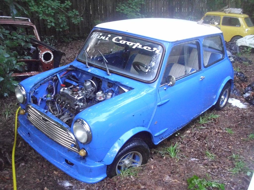
She previously belonged to a Fla. GRMer, who had purchased her as a several-year-old "restoration". My wife and I bought her over Labor Day weekend 2012, drove nonstop from Kansas City to Tallahassee, FL in a '90s Ford Ranger with a tow dolly, hooked up the car, drove nonstop home, all in the wake of Hurricane (who-the-hell-remembers). 2200 miles, about 40 hours.

Only trouble we had the whole way was a flat tire on the back of the Mini 10 minutes after we left the seller's house.
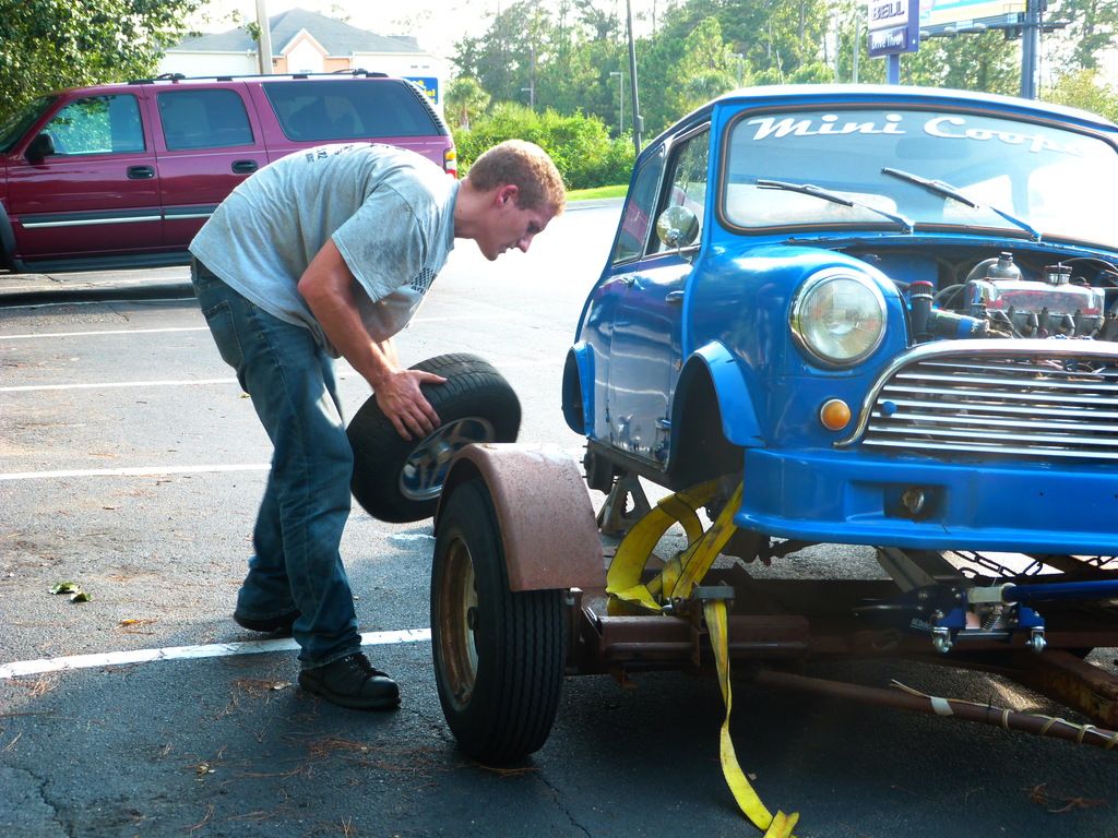
My wife still jokes (I think...) that this was the closest we've ever come to not being married anymore...
Shortly thereafter, I traded another GRMer this guy:
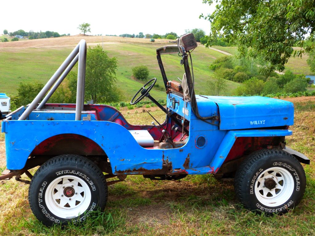
for THIS guy:
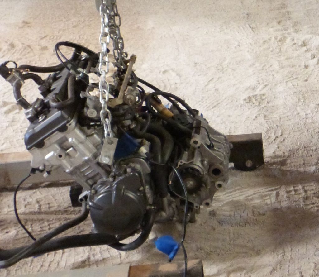
A 2001 Honda CBR929 engine and wiring harness.
Wife still likes the idea of FWD (boo), so I'll be installing the engine front forward, and using a chain-driven differential to send power to the front wheels.
Pulled the old engine out, and started scheming on how to make a square peg fit in a round hole, when BLAMMO!

I decided it'd be a nifty idea to go play soldier!
Fast forward 18 months. I'm finally back to somewhere I can play with my toys. My automotive ADD has been in overdrive, but Miss Jane is at the top of the list. No more new toys until I've at least made some measurable progress on this one.
Cleaned out the leftovers of the previous engine. Wiring harness (rats had been in it), brake lines, engine mounts, brake and clutch master cylinders all came out.
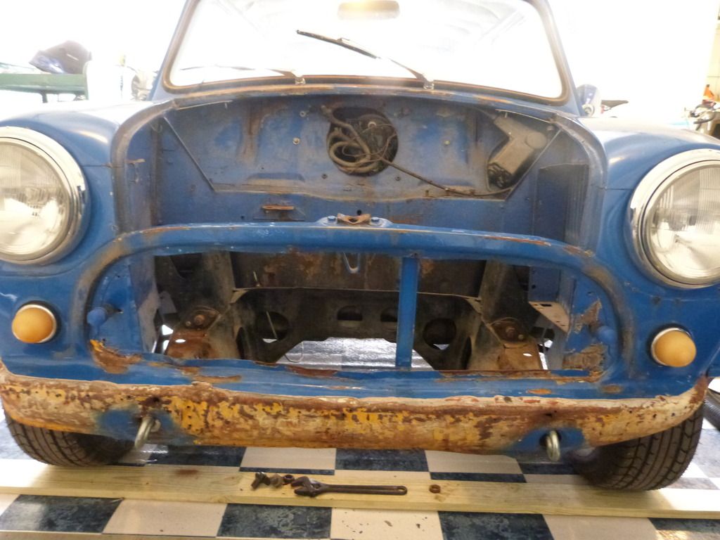
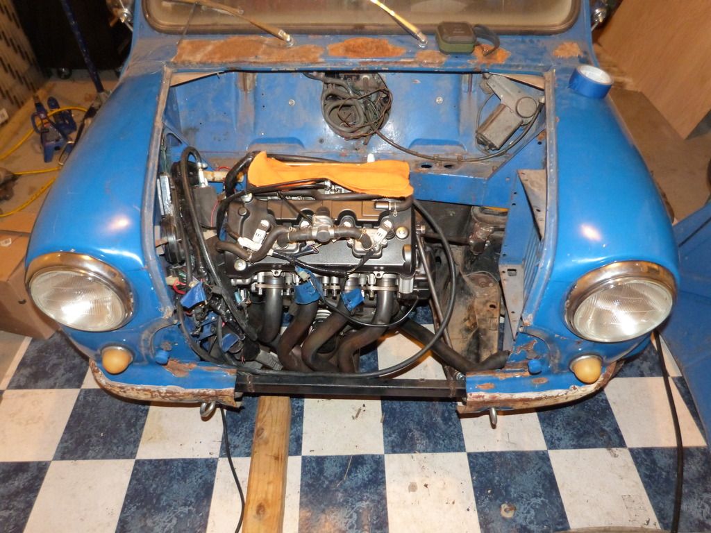
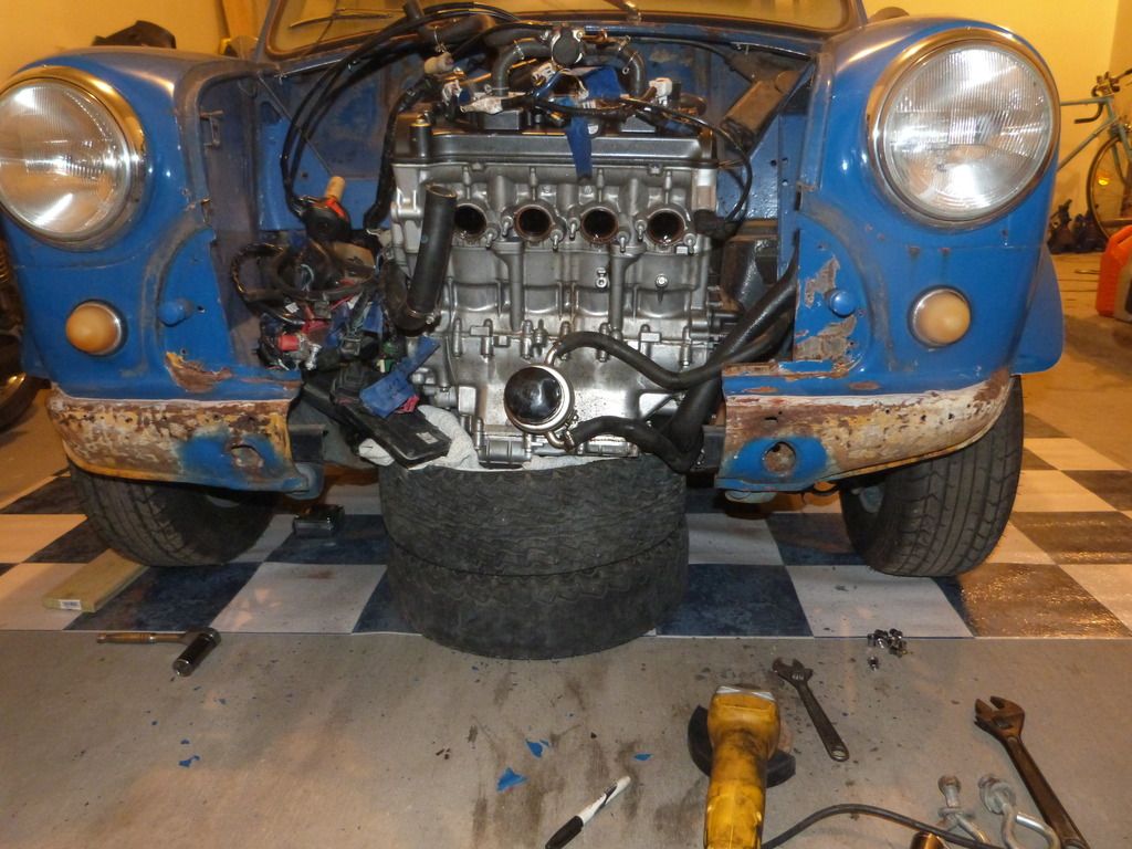
The front clip is pretty well buggered, so I'll be replacing it anyway... might as well resign myself to a little bit of cutting. And look at that, with a little creative removal:

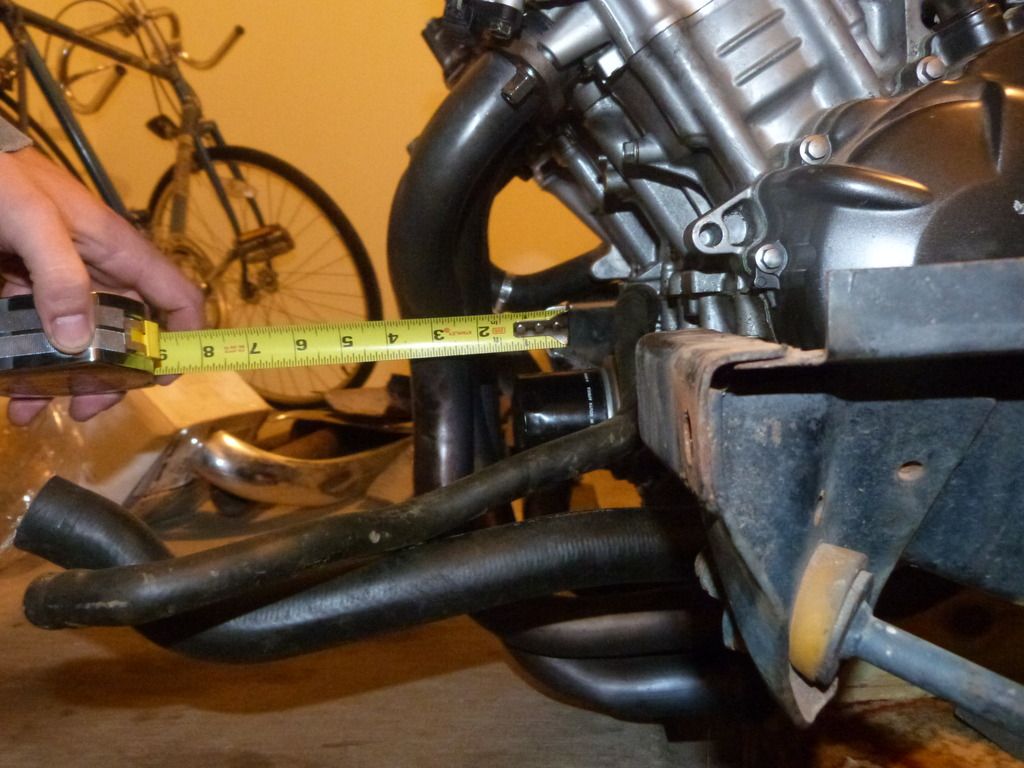
It all fits under the hood! Doesn't all play well together, though. VERY tight fit front-to-rear, and there's no exhaust manifold installed in that picture. The oil filter was sitting on the front beam of the subframe. More cutting and rearranging, and we get this:
At this point, I went back to the drawing board. I'm a child. I like cut and paste craft-type stuff.
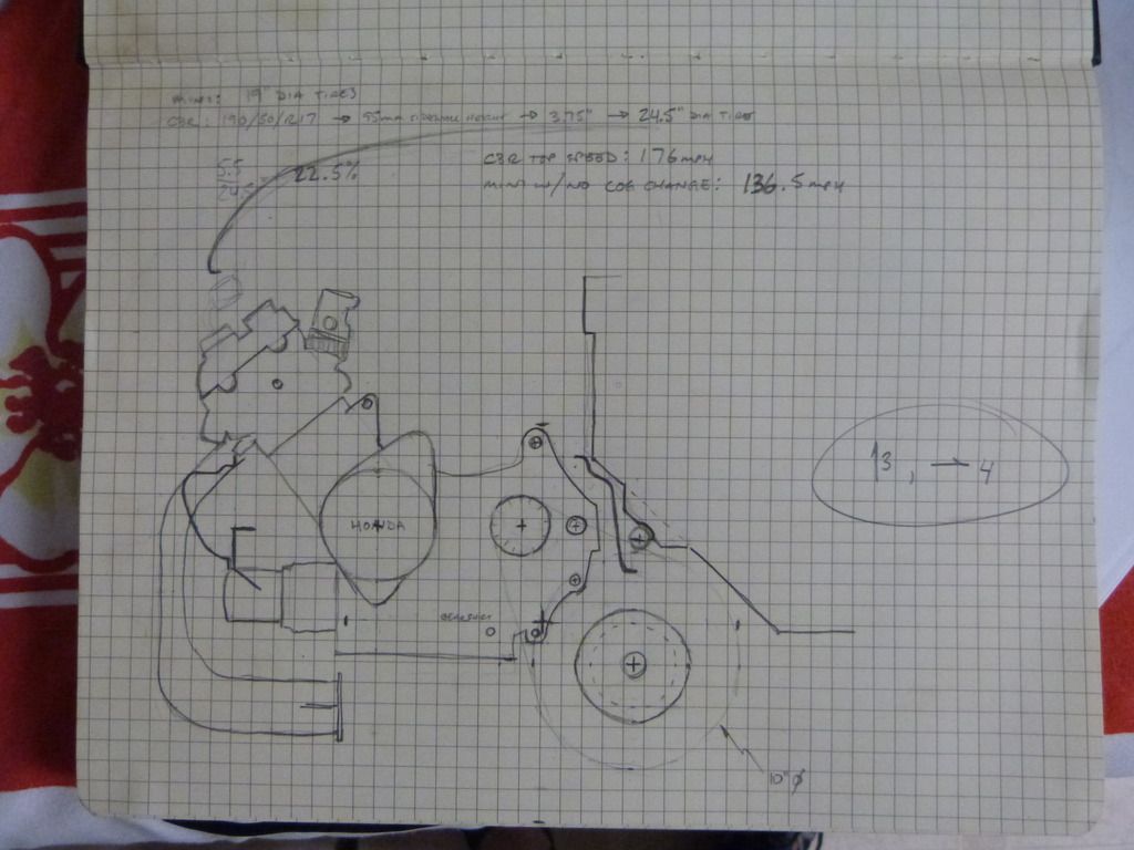
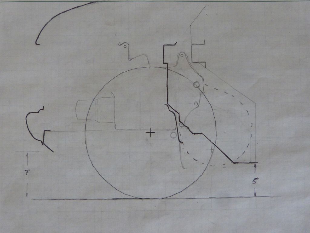
This ^^^^ shows the engine and differential position relative to the firewall and subframe (and front wheels, if you look close). One square = one inch. The oil filter and exhaust manifold are not playing nicely with the front clip, and the cog on the differential will only have 3 inches of ground clearance. After playing around with a paper cutout of the engine, I decided I wanted to move the engine up 3 inches and rearward 4 inches at a bare minimum. As the rear of the engine is already snug against the rear crossmember of the subframe, I'm going to have to restructure the subframe and sacrifice some footroom, but that's the only way I'll get the essentials inside the front valance.
As a side note: usually bike-engined Minis use Yamaha R1 engines. The R1 powerplant is shorter front-to-rear, with a (vertically) taller gearbox profile. This allows for the differential to be mounted almost directly underneath the gearbox, making for a very compact (again, front-to-rear) package. Hindsight is 20/20. I don't have an R1, so Berkeley it.
If I'm going to go hacking at the rear crossmember of the subframe, I might as well just...
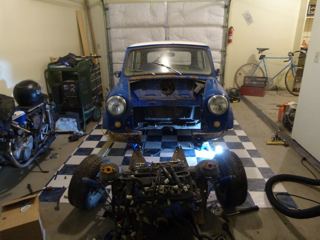
The subframe is bolted to the body in 10 places. Two bolts up front, 4 in the floorpan, and two at the top of each shock tower. Undo the shock absorber bolts and the steering ball joints. Lift body off of subframe, roll backwards, set on jackstands. Easy peasy. Sorry, no action shots. I was anxious to get on with it, so I pulled the subframe sans assistance/photographer.
I repurposed a hand-me-down dolly as an engine stand, which allowed me to better control the spatial position of the engine (it had been sitting on spare tires, which don't lend themselves well to precise engine placement). I want the engine as far to the passenger side as possible, so as to put the transmission output cog (and subsequently the differential) as close to the centerline as possible. This will make for as close to equal-length driveshafts as possible.
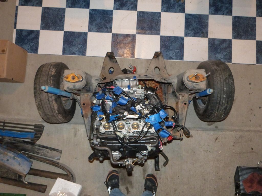
Not much clearance between the oil filler and the passenger shock tower.
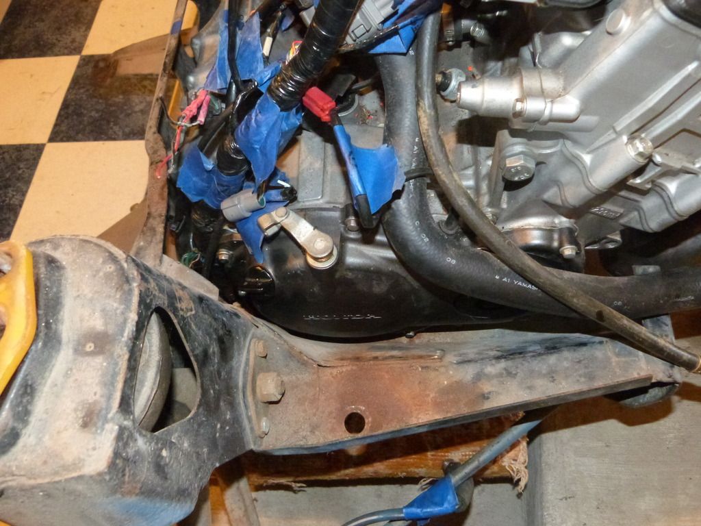
This is still the position shown in the sketch above. The oil filter still wants to live where the front crossmember of the subframe was, and the exhaust manifold would be protruding through the grill and front clip. Going to have to move back a little bit.
More cutting, and some pasting of previously cut bits (the front crossmember).

And throw the engine back on, tacking in a couple of makeshift supports to hold it where I want it.
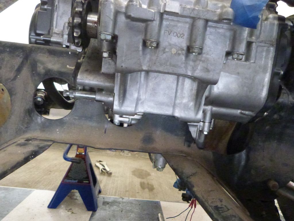
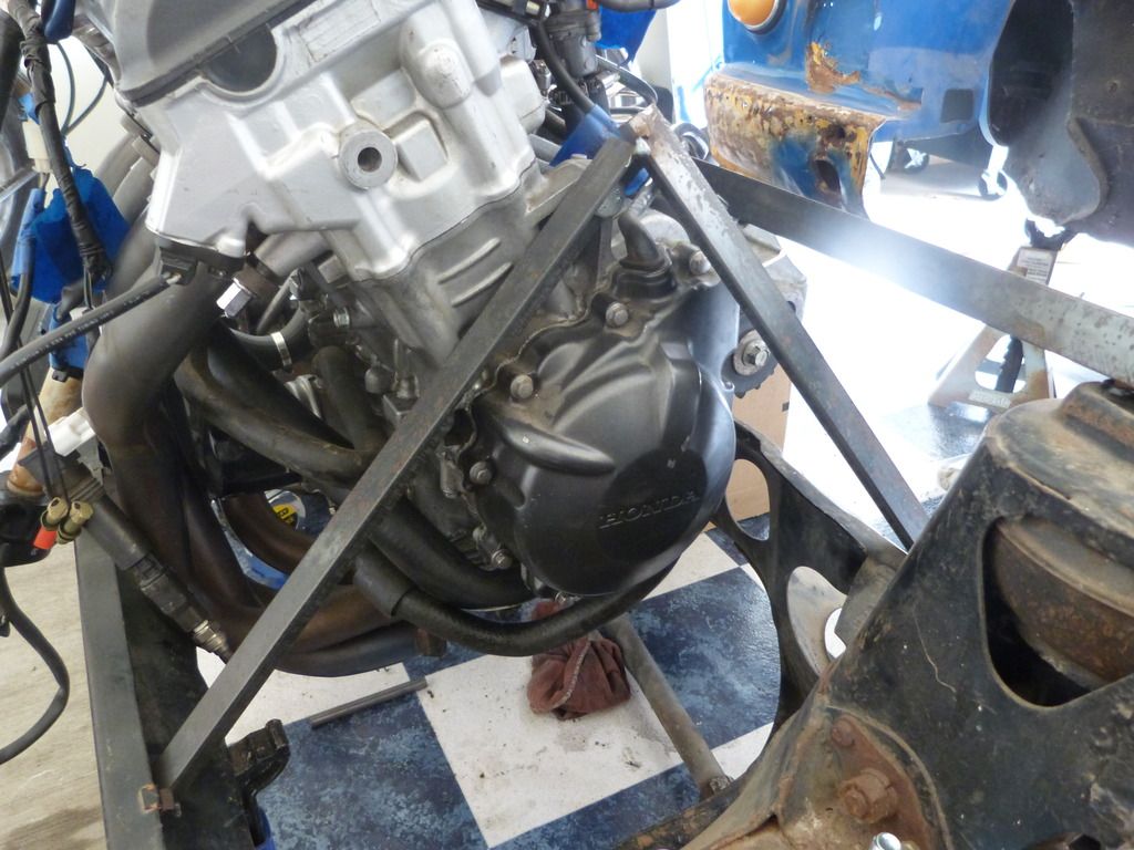
This gets the exhaust manifold inside the front crossmember and well inside the bodywork. The head is closer to the hood, but there's still several inches of clearance. Wife wants the car to sit an inch or two lower than it did in its engineless gutted state (which was where I took my measurements for the previous sketch). Where she wants it, we'll have 5 inches of ground clearance at the floor pan, and with this engine placement, 4.5 inches at the differential drive cog, so I can live with that. Will need to make a fairly stout guard for the chain and cog, but that's in the cards anyway.
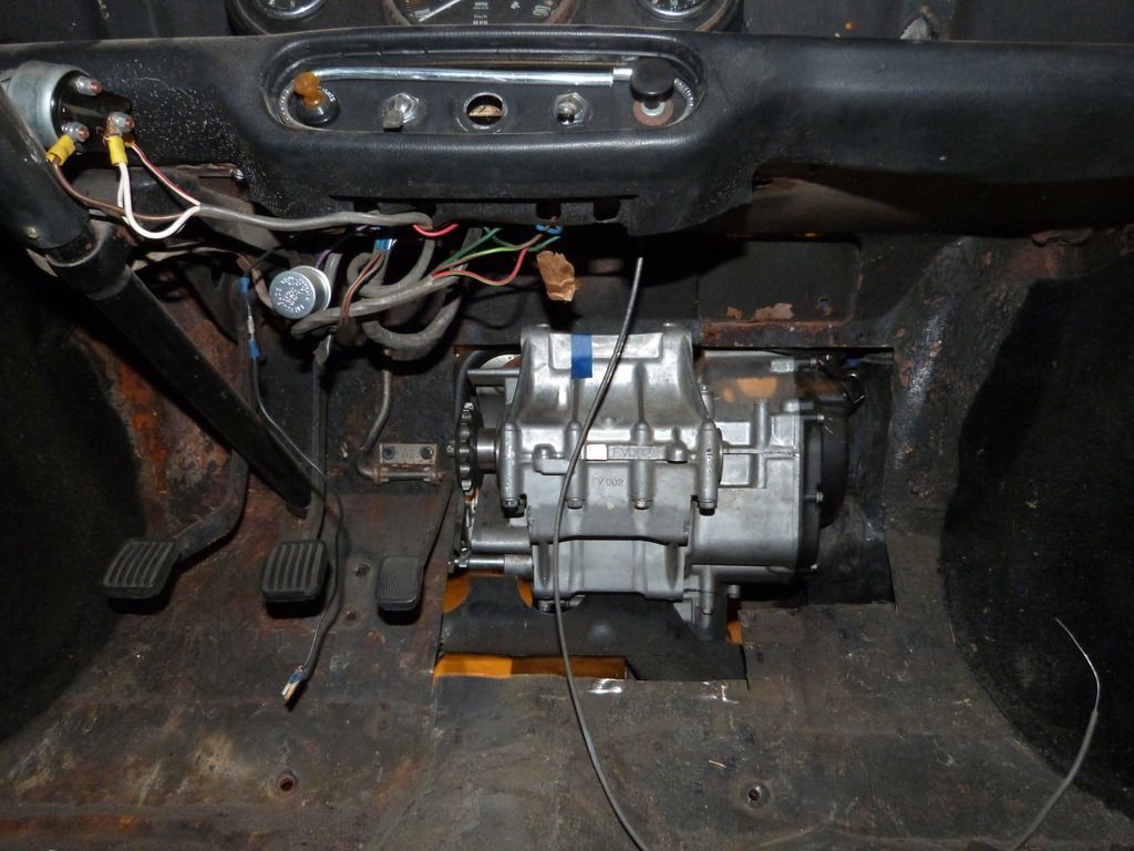
Sacrifices with this setup: going to lose about 6 inches of passenger-side footroom to make room for the tail end of the engine/gearbox, and almost a foot right in the center of the car to accommodate the differential and chain drive, and the steering rack is exactly where the differential wants to be.
Looking at my sketch and old pictures, I think I can put the rack under the engine and ahead of the rear crossmember. I'll have to put a knuckle or two in the steering column, but I had planned on changing the column anyway to improve the steering wheel angle and center it on the driver's seat. This should have the added benefit of further reducing bump steer, as it should make for shallower steering arm angles. Or something.
So, how to mount the new engine. This is my inspiration.

The engine and transaxle in my Beetle are solid mounted (because [daily-driven] racecar), and it's hellish to drive. Pretty sure that was the demise of my first transmission, and the second one isn't looking to healthy. So I want a little bit of cushion in Jane's motor mounts.
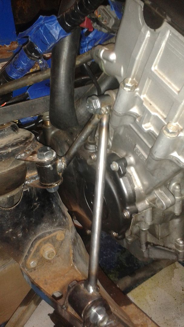
Enter the universal shock absorber bushing, and some hardware-store ingenuity.
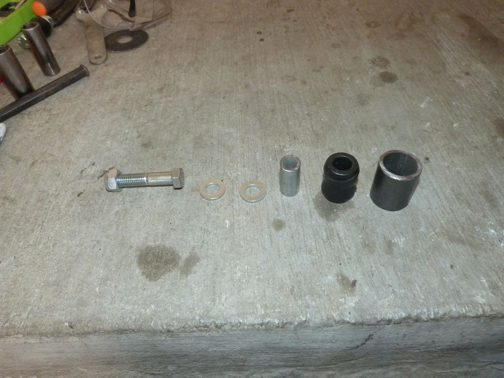
Cut the threads off a 3/8" x 4" SCH40 pipe nipple (is nipple a filter word?), cut the remaining pipe in half, insert into shock absorber bushing. Cut the threads off a 1" x 5" SCH40 pipe nipple, cut the remaining pipe in half, ream/taper the inside of the sections, and press in the shock bushing. 12mm hardware finishes the ensemble.
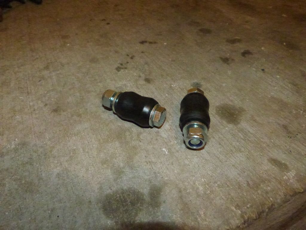
Since the driver's side engine mounting point is in use, I started with the passenger side mounts. Cut some brackets out of 1/8" x 2" strap, welded them to the subframe.

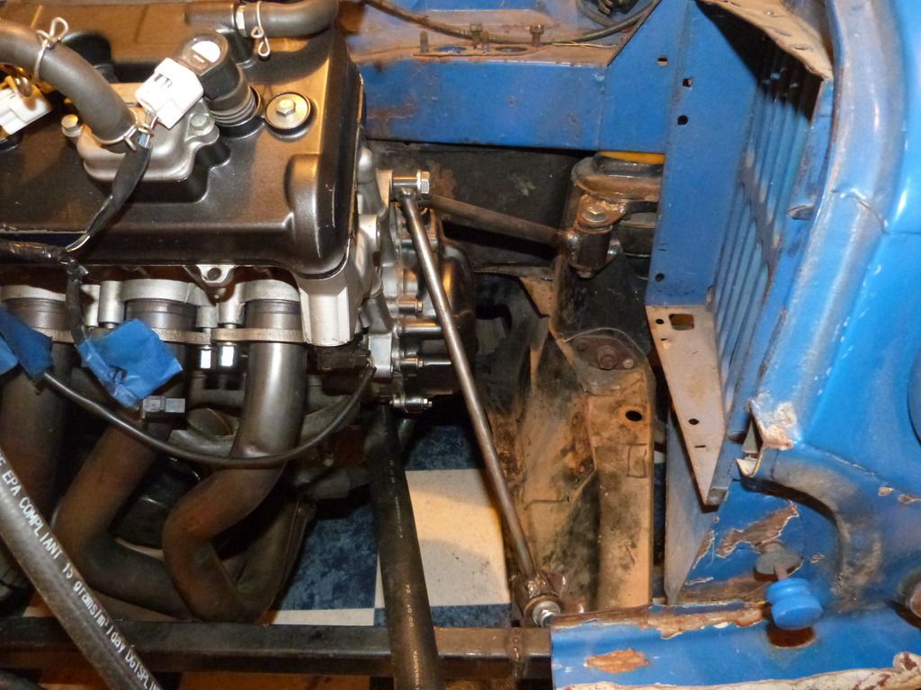
The bolt/bushing pair in the top center of this ^^^^ picture will be the top/engine side of the engine mount. Bushing is a 12mm drill bushing from McMaster. I've got a length of 1/2" .120-wall DOM tubing to run between the subframe-side bushings and the engine-side bushing.
More of the same on the driver's side. Just have one lower mount point done at the moment, going to put another at the top of the shock tower like on the passenger side.
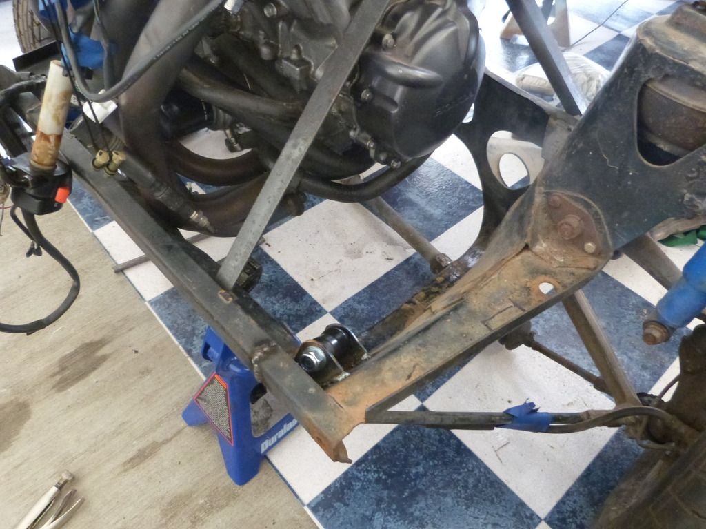
Aaaand that's where she sits. You're all caught up.
I need to go actually ream out the 1" sleeves for the shock bushings so I can press the bushings in, so I can tack weld the tubing between the lower bushings and the engine-side bushings. Once that's done, pull the tacked assembly, press the shock bushings out, weld the tubing on the rest of the way, paint them, repress the shock bushings in, install, repeat entire process for driver's side. I have no air tools, so I'm going to have to go find someplace to borrow a die grinder. Soon.
In the meantime, I'm trying to get the engine to fire. I've got the harness all hooked up, and it'll crank, but (after days of frustration and cursing) I discovered that the reason I can't get spark or fuel pump operation is that Honda had an anti-theft mechanism wired into the ignition switch. There's a diode that reduces the voltage into the ECU from 12V to 9V. If the ECU senses more or less than the prescribed voltage, it won't work. So now I'm waiting on the $0.73 voltage regulator to reduce the voltage from 12 to 9. Fingers crossed.
This'll probably be slow going. I don't have 6 kids like Tuna, but I will soon have 20-odd enlisted soldiers to oversee. I'll update when I can. Hope to be test driving by the end of autocross season, then pull it all apart again over the winter for finishing and paint.
![]() Yeah, I know. Fat chance.
Yeah, I know. Fat chance.


