AngryCorvair (Forum Supporter)
AngryCorvair (Forum Supporter) MegaDork
7/22/20 11:05 p.m.

In reply to barefootskater :

My first idea was to tie the Audi mount forward to those unused holes on the C5 subframe, but this was a no-go because of rear bar packaging, plus the force paths were not good. So I dismissed the Audi mount and turned my thoughts to using those side bosses, which in hindsight is a terrible idea because those bosses are designed to hold exhaust hangers, supporting probably less than 20% of the weight of the trans. I'm glad the DIY bubbly urethane failed before I had a chance to crack the trans case!

SaltyDog
SaltyDog HalfDork
7/24/20 3:51 p.m.

https://gmauthority-com.cdn.ampproject.org/v/s/gmauthority.com/blog/2020/07/artist-renders-corvair-with-c8-corvette-powertrain/amp/?amp_js_v=a3&amp_gsa=1&usqp=mq331AQIKAGwASDYAQE%3D#referrer=https%3A%2F%2Fwww.google.com&amp_tf=From%20%251%24s&ampshare=https%3A%2F%2Fgmauthority.com%2Fblog%2F2020%2F07%2Fartist-renders-corvair-with-c8-corvette-powertrain%2F


Just saw this article and thought "AngryCorvair is SO far ahead of these guys!"

AngryCorvair (Forum Supporter)
AngryCorvair (Forum Supporter) MegaDork
7/30/20 7:42 a.m.

Dang, it's been a minute since my last update. I have done a lot of work but some of it got binned as "educational", ie I'm going to redo it. 

To use the C4 fuel pump assembly, I need my tank to be 14-1/2" deep, but to fit the boat tank into the car with the least mods, it's only 13" deep. I pulled some 1.5" x 1.5" x 1/8" 6061 angle from the Aluminum scrap bin at Alro Metals in Livonia MI and welded up a riser for the pump assembly, which I will weld to the top of the tank.

At only 1/8" thick, there's not enough material to tap for M6 bolts, so I cut some weld-in inserts from a scrap length of 3/4" diameter 6061. I also drilled and tapped the first inserts while still chucked up in the lathe:

I used the gasket to lay out the bolt holes, and I opened a couple of them up with a step bit to 3/4" so the inserts would hold themselves in place for welding.

The education began here, because using the step bit in my wobbly drill press made a hole about .752" and the 3/4" round stock measured .750".  The result is that my "snug fit" was actually a "fall through". What I learned: use a step that's smaller than the nominal OD of the round stock, mic the hole, and turn the end of the insert down to a .001" press fit. At this point I decided to build a bunch of variants to see how each one turned out. I drilled holes 5/8, 9/16, and 1/2. And I turned shoulders on the inserts at 1/4" (proud of surface by 1/8"), 1/8" (flush with surface), and .065" (recessed by .060").

Here's what it looks like after welding. Bottom right is smallest step bit hole, with recessed insert:

I will mill the top surface flat, then take a close look at the weld areas for cracks, porosity, etc. as far as weldability, the recessed 1/2" diameter was easiest and will require least material removal to make flat. And because the smaller hole is farther from the edge of the angle, it reduces the chance of cratering, which is important since the top surface is a gasket surface on a gas tank!

i have many hours in this bit of education, spread over several days. V1 is a hot mess. V2 will be a winner. 

Robbie (Forum Supporter)
Robbie (Forum Supporter) MegaDork
7/30/20 8:50 a.m.

haha I have been 'educating' myself with my build this week too. 

AngryCorvair (Forum Supporter)
AngryCorvair (Forum Supporter) MegaDork
7/30/20 10:35 a.m.

In non-challenge-specific MonZora news, my buddy Jay reminded me that a mutual friend is a bigwig in OE sales for the parent company of Falken, so I reached out and asked if he had any bigwig discount authority. Turns out he does, so I got a C5-sized set of Azenis FK510s at 40% off.

preach
preach Reader
7/31/20 11:12 a.m.

Nice!

iansane (Forum Supporter)
iansane (Forum Supporter) Reader
7/31/20 11:24 a.m.

Score!

AngryCorvair (Forum Supporter)
AngryCorvair (Forum Supporter) MegaDork
7/31/20 11:32 a.m.

Previously, I had basic CAD for trans mount plate and tabs. I transferred CAD to a chunk of 1/8" steel from the "welding practice" bin at Alro and roughed it in on the mill at work:

then attached it to the trans and marked for clearance to rear bar:

I lost the CAD file for my mounting tabs so I recreated that, then went to the bin of C5 scraps yet again, and found 4 places I could scrounge pieces just barely large enough:

I transferred CAD to steel, drilled holes at inside corners, cut with death wheel, and smoothed with flap disc. I only got tabs bent on 2 of them before I had to pull the plug. Took AK1 to campus (holy crap, I have a kid in college!?!?) then spent a few days with my wife being tourists.

AngryCorvair (Forum Supporter)
AngryCorvair (Forum Supporter) MegaDork
8/10/20 10:10 a.m.

i haven't been very good at providing timely updates and taking pix recently, but i'll get back into that habit.

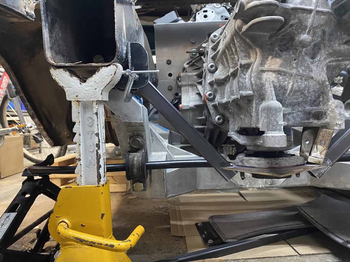
trans mount progress:  because of how the powertrain installs, the mount has to be removable from the bottom. using the Audi mount, i was planning to use 1" square tubing legs out to the bottom surfaces of the C5 frame rails. i quickly ditched that plan when i realized how much of a PITA it would be to weld the mounting tabs in that position. so i sacrificed some weight gain to improve ease of assembly, and put the tabs on the top inboard corners of the C5 rails. i think it's a better design because it loads the legs more in tension and less in bending vs the low mount. either way, the plate shown in previous post doesn't change. i notched the corners to accept the 1" square tubing, and clamped everything in place (pic shows attaching at bottom of rail, but process is the same):

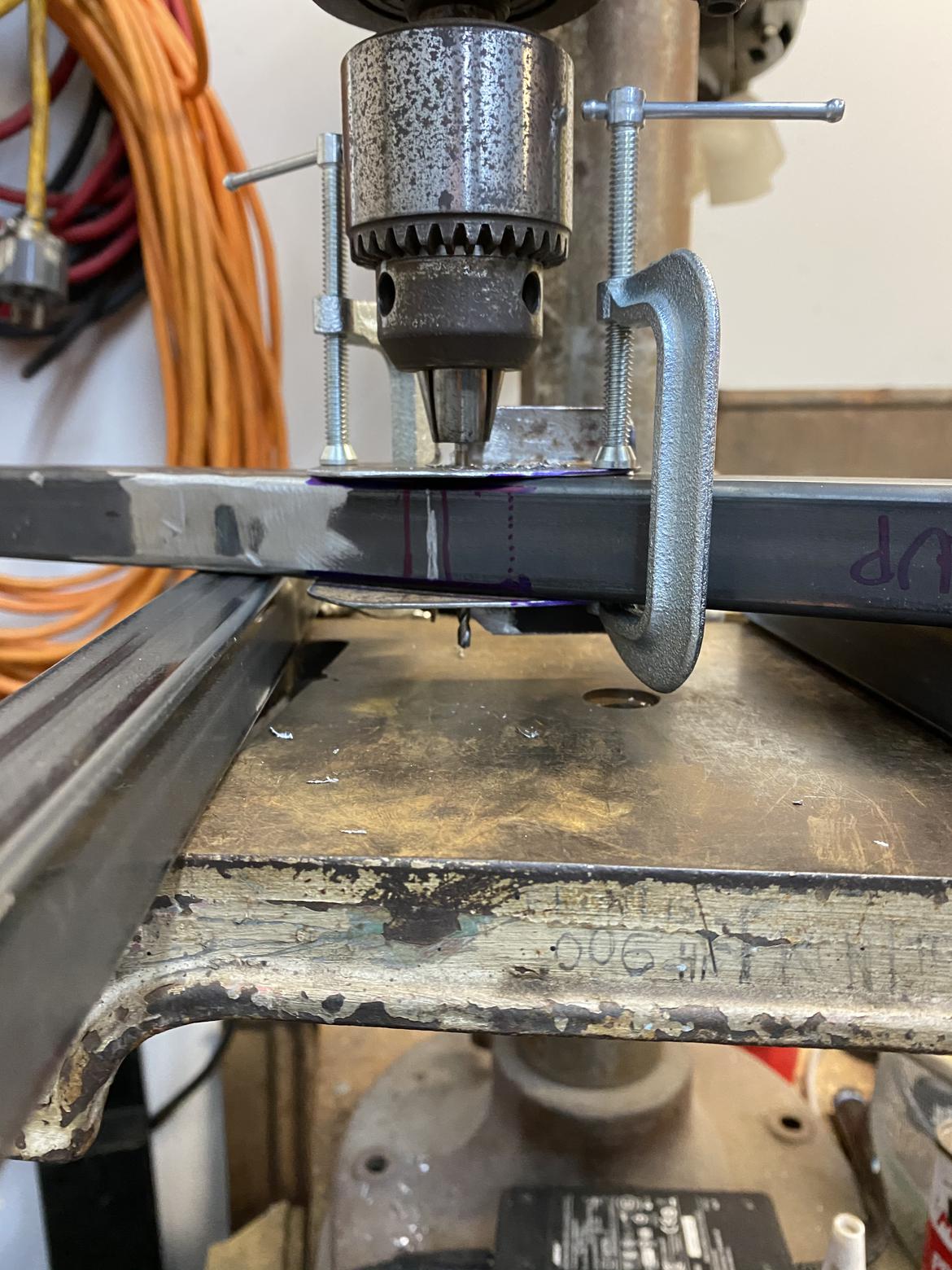
then used drill press to add bolt holes through mounting tabs and legs in one straight shot:

and tacked everything in place:

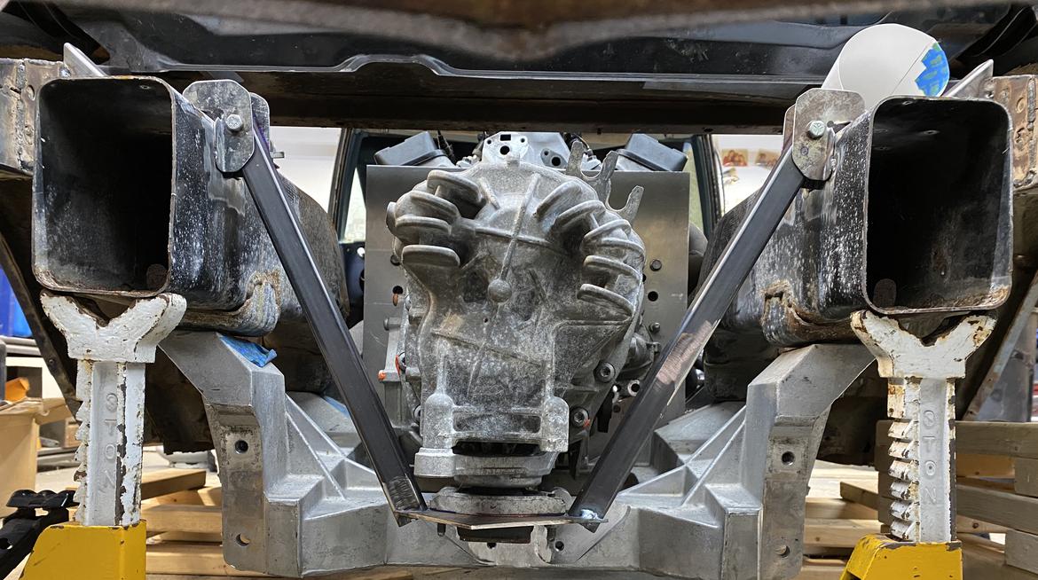
i'm going to trim the mounting tabs and add a piece to connect them together on each side. it will also attach to the upper surface of the C5 rails, farther outboard than the current attachment. this may only serve to make me sleep better at night, but i think it's a good idea to distribute the forces over a larger area. i also need to add a "spine" to the bottom plate to stiffen it against the bending loads where the legs tie in.

gas tank progress:  as previously posted, i had to build a 1.5" riser to use the C4 fuel pump assembly in the boat tank.  V1 was a "learning experience" for a lot of reasons, so i took a different approach to materials and process for V2. i started by laying out the gasket outline on a corner of the unused portion of the tank (rem: tank was 26" long, now cut down to 16").

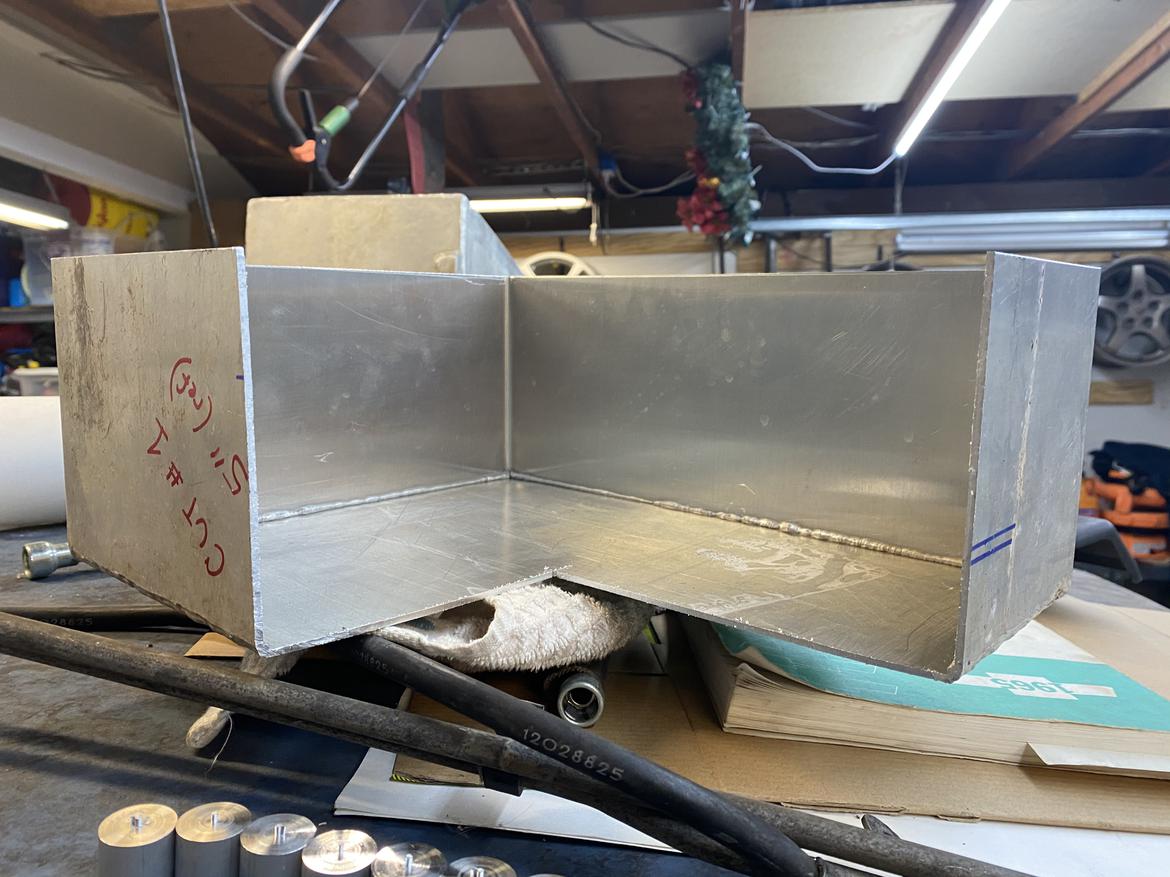
using this corner gives me the top and 2 of 4 sides in one piece. so i cut it 3" high, then took a 1.5" slice off the bottom. this gave me the other two sides in one piece. a little cleanup of the corners and a slight trim of the lengths and it was ready to be welded.

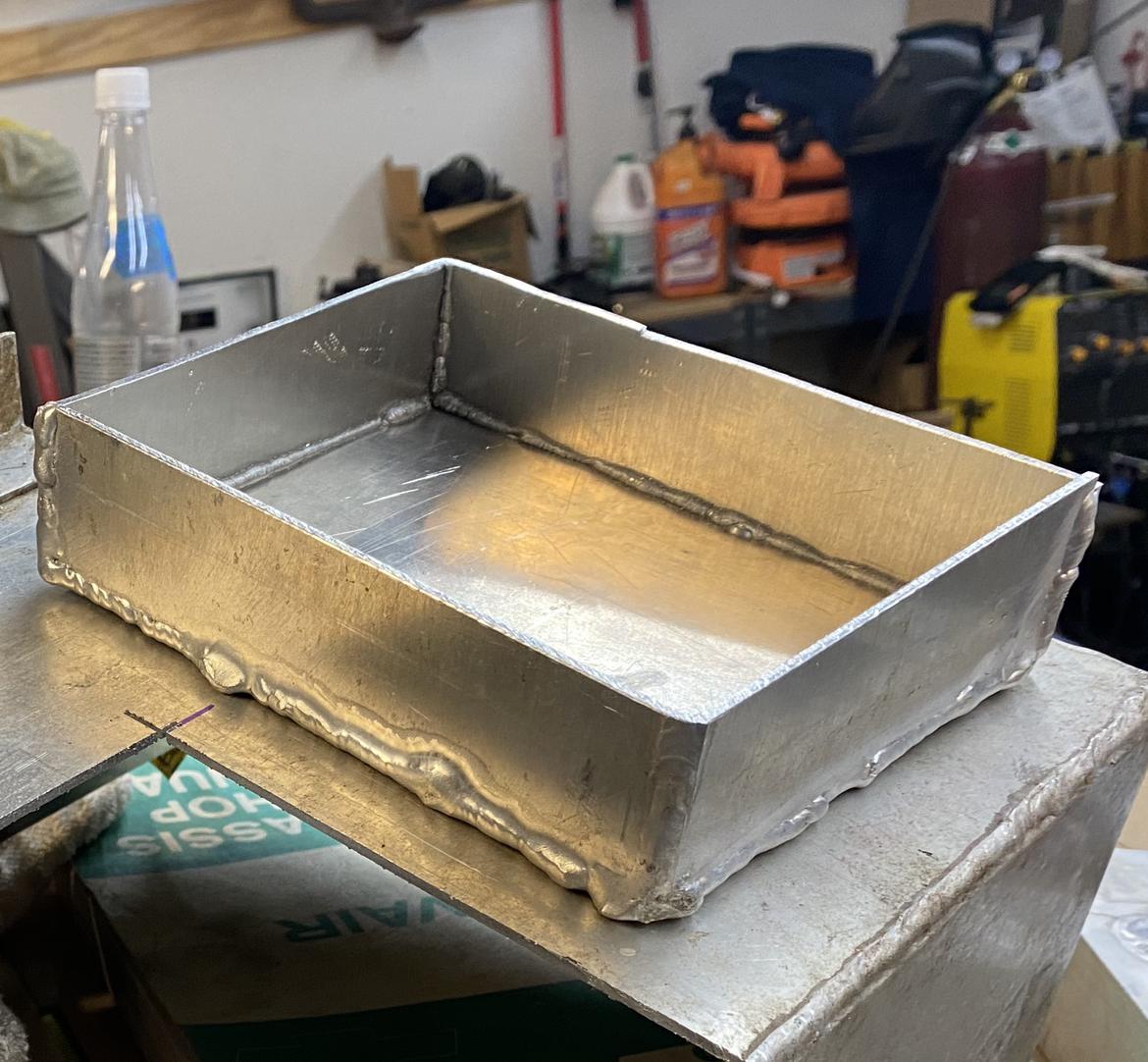
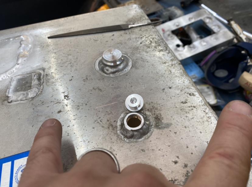
from V1 i learned to use the 1/2" step bit for bolt holes, then measure each hole and turn a shoulder on each insert to make it a light press fit that sat slightly below the surface. this gives me a nice seam to weld and will only require a light skim cut to make the gasket surface flat. so here's V2 and the 9 inserts, fit up and ready for welding:

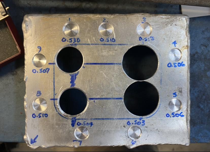
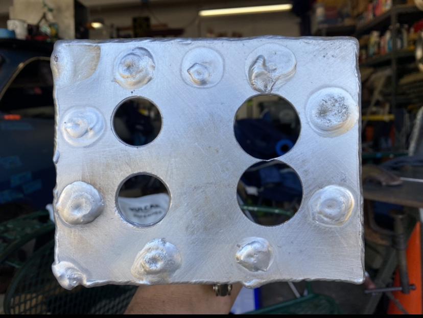
note that there are four big holes in the top. yeah, V3 wouldn't have them at this point in the process, but i was already set up on the drill press so i opened them up. having those holes there robbed me of thermal mass in welding the inserts, and i got a shrinkage crack because of it (not a problem though, as it's in an area that will be removed). those holes are different sizes because my 1-3/8" step bit isn't sharp anymore. i'll be connecting them with the jig saw anyway, so an exact match on the radius isn't strictly required. i still need to set it up on the mill and skim the gasket surface, then flip it and level the height of the perimeter where it will be welded to the top of the tank. V2 with inserts welded:

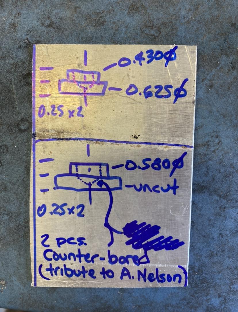
as for the tank itself, there were three ports on the top surface i needed to remove and close: 1-1/2" dia fill tube, 3/4" pickup tube, and 5/8" vent tube. for the large one i cut a patch with the jig saw and smoothed the edges with a flap disc. for the other two, i turned plugs from 3/4" round stock. inspired by the Nelson family, i added lightness by counter-drilling the underside of the plugs :-)


then everything went straight to Hell when i welded them in place:

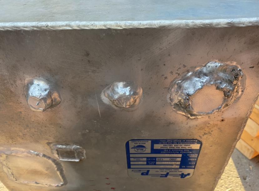
  • maybe because i used a wire wheel that wasn't stainless and wasn't dedicated to aluminum? i did follow the generic wire wheel with my Al-only stainless brush, if that matters.
  • maybe because of the thickness difference requiring so much heat only on one side of the joints?

sure, they look like E36 M3, but do they leak?
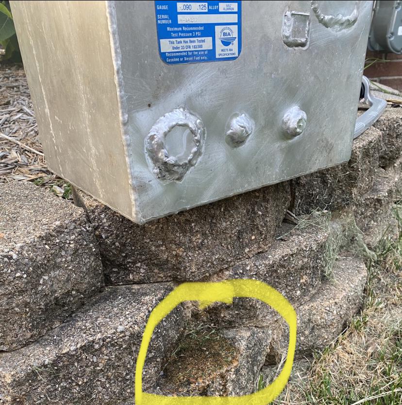
berkeley.

anyway, another lesson learned. these look so terrible that, even if that one didn't leak, i'm cutting them out and replacing with a single flat patch from the leftover tank bits, which gives me an easier-to-weld lap joint of equal materials.

learning by failure takes a lot of time, but I'm getting better at it.

AngryCorvair (Forum Supporter)
AngryCorvair (Forum Supporter) MegaDork
8/11/20 6:38 p.m.

Bridgeports are cool.

got the gasket surface flat, then flipped it in the  vise and got the bottom flat too. Nice tight gap for welding:

also made a poster board template of the open end of the tank, which I transferred to a "usable drop" of 6061 sheet, and got the shape tightened up for welding:

Currently standing in line for a food truck. One cool thing our sub has been doing all this summer is having a different food truck come in each week. Not sure I'm gonna get any welding done tonight, but my tapeworm won't mind.

also, I bailed on cutting out the leaky patch. I just re-flowed it with the torch and added a tiny bit of filler to a couple spots. No more leak!

AngryCorvair (Forum Supporter)
AngryCorvair (Forum Supporter) MegaDork
8/12/20 11:26 p.m.

Tonight I broke out the jig saw and removed the center of the fuel pump riser:

then cut a clearance hole in the top of the tank for the pump assembly to pass through, and dropped it in to check alignment. Guess what?

Not sure how I messed this up, but it'll be ok. I'll patch it with a strip from the piece I removed. I must have measured the gauge float arm wrong.

so, on with the cleaning, aligning, clamping, and welding. Tacking was uneventful, and first bead went pretty ok for my experience level:

then I burned through a spot on my second bead, and building up around and over the hole consumed a lot more filler rod than I expected:

and I had a similar experience on bead 3:

Can't hate it overall though, because I have clearance for both the gauge float:

and the pump tubes:

tomorrow I'll cut, prep, and weld that patch, then make a baffle for the pickup, so I don't starve in long corners or under acceleration. Thinking about a magnet on the baffle and another stuck to the bottom outside, instead of risking another welding "education".

Here's a side view of how it all lines up.

After I install the baffle, I'll fit and weld the tank end in place. Then I can make the mounts and call the fuel tank done.

iansane (Forum Supporter)
iansane (Forum Supporter) Reader
8/13/20 9:06 a.m.

Nice job! That riser is a convenient solution. And "aluminum caulk" is a perfect description of my welds too.

Daylan C (Forum Supporter)
Daylan C (Forum Supporter) PowerDork
8/13/20 9:32 a.m.

I wonder about the magnet letting go and causing the annoying noise we talked about. Or jamming up the float. Possibly a non issue though and definitely a lot less chance of another leak. 

I wonder if you could find an epoxy that will play nice living it's whole life submerged in fuel...

Patrick (Forum Supporter)
Patrick (Forum Supporter) MegaDork
8/13/20 9:44 a.m.

I would bend up a pickup tray and give it a few tacks around the perimeter, not sure i trust a magnet.  
 

"the $2000 challenge, where you can spend $75 on something or spend $40 and dozens of hours to save $35 in budget room to use a fuel pump you already had"

AngryCorvair (Forum Supporter)
AngryCorvair (Forum Supporter) MegaDork
8/13/20 10:08 a.m.
Patrick (Forum Supporter) said:

"the $2000 challenge, where you can spend $75 on something or spend $15 and dozens of hours to save $60 in budget room to use a fuel pump you already had"

exactly. plus i like using OE parts from as few donors as possible.  there are only a few wear items on this car that are custom / fabricated:

  • flywheel is custom but uses A4 pilot bearing. friction surface is replaceable. clutch disc, pressure plate, throwout, master, slave are all A4.
  • all front suspension steering and brakes are C4. steering column and intermediate shaft are modified but they're not really wear items
  • all rear suspension is C5 (with C5 front brakes). narrowed cradle and transverse leaf, yes, but easily duplicated if ever required.
  • halfshafts will be spliced together from A4 and C5, but CV joints are replaceable so as long as the spliced shaft itself doesn't fail...

anyway, you get the picture. the donors are common enough that this car could be maintained 100% from Rock Auto for the next 30 years.


AngryCorvair (Forum Supporter)
AngryCorvair (Forum Supporter) MegaDork
8/13/20 10:21 a.m.

Enuff Mircales here to blow yer brainz!! Magnets JUGGALOS FOR berkeleyIN' MAGNETS! HOW DO THEY WORK?! A Reference for the Rest fU! FREE eTips at ICP.COM SYCHODICK McFUGNUTZ Muthaberkeleyin' Magnet Guy text yellow font advertising

NOHOME
NOHOME MegaDork
8/13/20 10:28 a.m.

Dipping the tungsten in the puddle are we?

AngryCorvair (Forum Supporter)
AngryCorvair (Forum Supporter) MegaDork
8/13/20 10:38 a.m.

In reply to NOHOME :

Several times. I didn't have good support for my torch hand and I dipped several times last night. Was getting frustrated so I took some goofy pix to break the tension. Drank a big glass of water, let the torch cool, and got back at it. 

TurnerX19
TurnerX19 SuperDork
8/13/20 10:54 a.m.

Refresh my memory. Why do you need a magnet? Where would ferrous particles come from in the fuel?

Daylan C (Forum Supporter)
Daylan C (Forum Supporter) PowerDork
8/13/20 11:01 a.m.

In reply to TurnerX19 :

He just wants to mount the baffle that way.

AngryCorvair (Forum Supporter)
AngryCorvair (Forum Supporter) MegaDork
8/13/20 11:14 a.m.
Daylan C (Forum Supporter) said:

In reply to TurnerX19 :

He just wants to mount the baffle that way.

Yep, just looking for a way to avoid welding. See above pix if you're wondering why LOL.

Two magnets, one inside the tank and one outside. Because aluminum.

TVR Scott (Forum Supporter)
TVR Scott (Forum Supporter) Dork
8/13/20 11:55 a.m.

Come on now.  You're doing really well with the aluminum welding.  Pull up your big boy pants and do it the right way.

Might be a little more forgiving if you broke a 90 deg flange on each side of the baffle.  Then a relatively small tack would hold it in place and would be less likely to blow thru the outside wall.

In reply to TVR Scott (Forum Supporter) :


NOHOME
NOHOME MegaDork
8/13/20 1:43 p.m.

I think you are doing about what I would expect for a new alloy welder. I don't do any better because I never do enough to get over the hump. Stuck together and leak free is all I would ask. 


TVR Scott (Forum Supporter)
TVR Scott (Forum Supporter) Dork
8/13/20 1:55 p.m.

This gas-tank fabrication sure can be baffling...

You'll need to log in to post.

Our Preferred Partners
9LheDLYYtwaRP5OqTH9LCXIm24uNUgQ7sp44WorFQKuMvL7i6LnxO9aENxmQDVl3