I'm taking a little time to make sure I get the rear frame right, and that means figuring out the rear suspension. Here's a really rough idea of how I intend to lay it out:

I'll try to mount the lower links on the outside of the chassis, and the third link will likely be offset to the right side of the differential. Might see about building a bracket that runs over it to center it better, though. The shocks will likely stay in the stock position on the axle, using the leaf spring mounting plate. Depending on how much threading is on the u bolts, I may need to add some shims to replicate the thickness of the leaf spring. There are spring pockets on the Trailblazer rear end that I can transfer over to the S10's axle, and then I can build some sort of adjustable mount on the frame for ride height/weight balance. If we do find some appropriate coilovers, I can instead strengthen the shock mounts, and just use them.
In an effort to save some fab work (and money), I'm using a cheap 4 link kit, that I intend to convert to 3 link. It also has provisions for a panhard bar, but all the links are 24" long(plus heim joint length), and I'd rather run a longer one, so will probably re-purpose the one from the Trailblazer. It's about 39" long, and I can shorten it and make it adjustable with some large diameter allthread. I could also use the one that came with the ZR2 rear axle, but it is shorter, and the curve in it is designed to go up higher around the upper part of the rear differential. At the very least, I should be able to reuse its bracket, as it just bolts to the axle.
I may have overestimated the width of tire I can fit with the link on the outside, but 275 or 295 should still fit on the wheels I have, and we could go wider if we find the right offset.
In order to get the cut right, I want to know where the lower link mounts are going to be attached to the side of the frame. Since I've been meaning to relearn CAD at some point, I downloaded FreeCAD today, and started stumbling around. First step I wanted to do was replicate the four link brackets. This is about as far as I got:


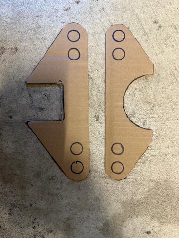
I'm running into issue with fillets screwing up other dimensions, and on the axle side, I appear to not have every line connected properly, as it won't let me convert it to 3D. Again, if you have any suggestions as to a different program to use, let me know. I was hoping not to have to set up an account to use Fusion, and didn't like the idea of using Solidworks in the browser, but maybe I have to reconsider. I may just trace everything out on corrugated cardboard(including multiple link lengths), and figure it out on the truck as it is.
With the heim joints installed (and with 1.5x diameter thread engagement), it looks like my max link length bolt center to bolt center will be 30", which seems longer than will be necessary. The bigger concern is adjustability. Without reducing thread engagement, or getting thinner jam nuts, the most I can change the length by is 3/8". Having never messed with this kind of setup, I have no idea if that is enough.
One minor issue I'll have is the kit is designed for a 3" diameter axle tube, not the 2.75" tube I have. Since I only need the bottom half of the bracket (unless I set it up to be able to be converted to 4 link), I think I can get away with it, maybe with a little gusseting. A not so minor issue is backup parts. I was planning on buying some spare heim joints to use for testing, so I wouldn't risk damaging the ones in the kit, then swapping to them right before the challenge. However, they are a metric approximation of a 5/8" joint, and it looks like I can get right hand threaded ones cheap, but left handers, not so much(Edit: found lefties cheap, so problem solved). Need to do a little more digging. I will at least have a few spares if I stick with the three link idea, and stay with rubber bushings for the panhard bar.