
I’ve browsed the forums for a little over a year now and decided it was about time to make an account and maybe add a little to the community.
My name is Adam Doyle. I’m 26, from Red Oak, TX and for the last three months, my dad and I have been building a mid-engine, tube chassis street/autocross/track car from an 07 Chevrolet Cobalt LS donor car. We’ve thought about making a car like this for years and things finally lined up for us to do it this summer.
As a little bit more of an introduction, I work at the family business that my dad started about 10 years ago. We are a CNC machine shop that specializes in making aircraft fittings. Our hobbies have ranged from RC cars, planes and helis to circle track racing. We built our dirt track cars ourselves and hope to use that experience with this project.
We started with a few goals:
Small budget
Keep it light: This will allow us to have good performance without needing to break our first goal with costly engine upgrades.
Use up the donor: Reusing as much as possible will save money and we get some neat features like automatic headlights, ambient temperature, fuel mileage, etc.
Make a fun car
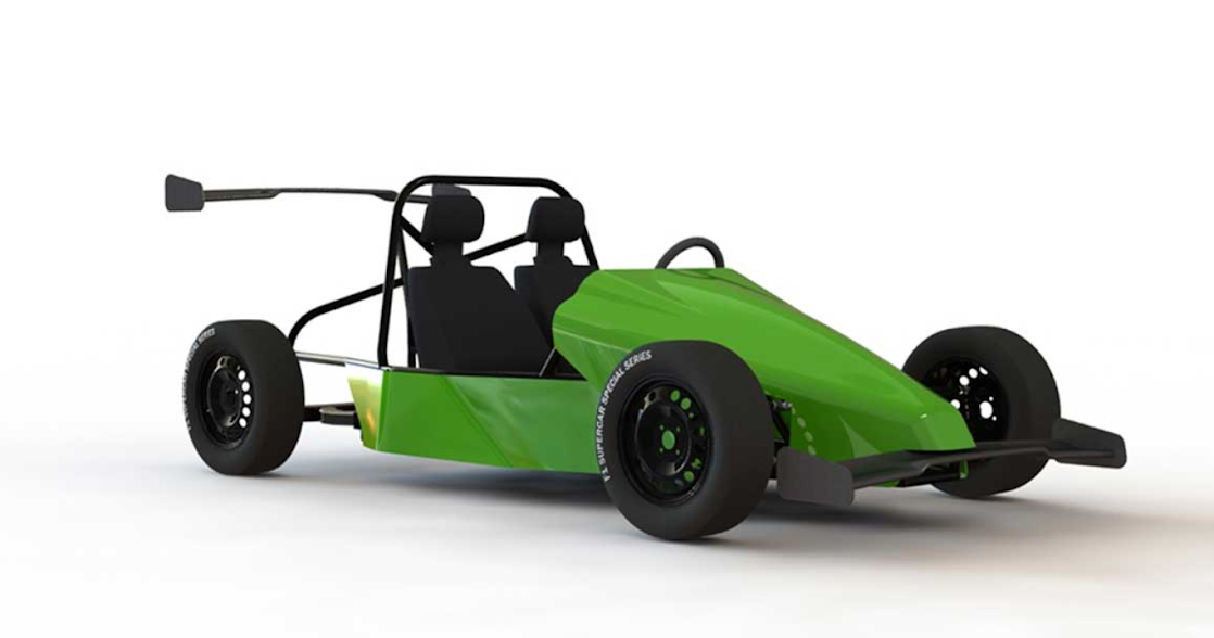
We call our car the Goblin because the name Cobalt comes from the german Kobold that equates to Goblin. Here is a picture of the model we've drawn in Solidworks. Don't mind the magic holding on the spoilers and rear tires.
Updated website: The interactive model linked below still exists, but for more up to date information, check out our main site: DF Kit Car
I’ve also put together a little website where you can spin around the 3D model of the car here: Goblin Info. It is a work in progress and might not work on all devices, but on most you should be able to spin the model around by clicking and dragging (or touching and dragging on touch devices).
My first few posts will be to catch y’all up to where we are at the moment. After that I’ll try to update often.
May 2 - The Donor
We started out by buying a donor car via copart.com. We would have prefered a 2009 or 2010 Cobalt (LAP Ecotec engine for a little bit more horsepower with variable valve timing, tire pressure monitoring system and newer car overall). Due to availability and keeping the cost low, we went with a 2007 Cobalt LS sedan with 129k miles.
This Cobalt had been wrecked in the front (as are most potential donors) but from a visual inspection, the damage didn’t seem to go beyond the radiator. One big plus was that this car cranked up and could still move under its own power.
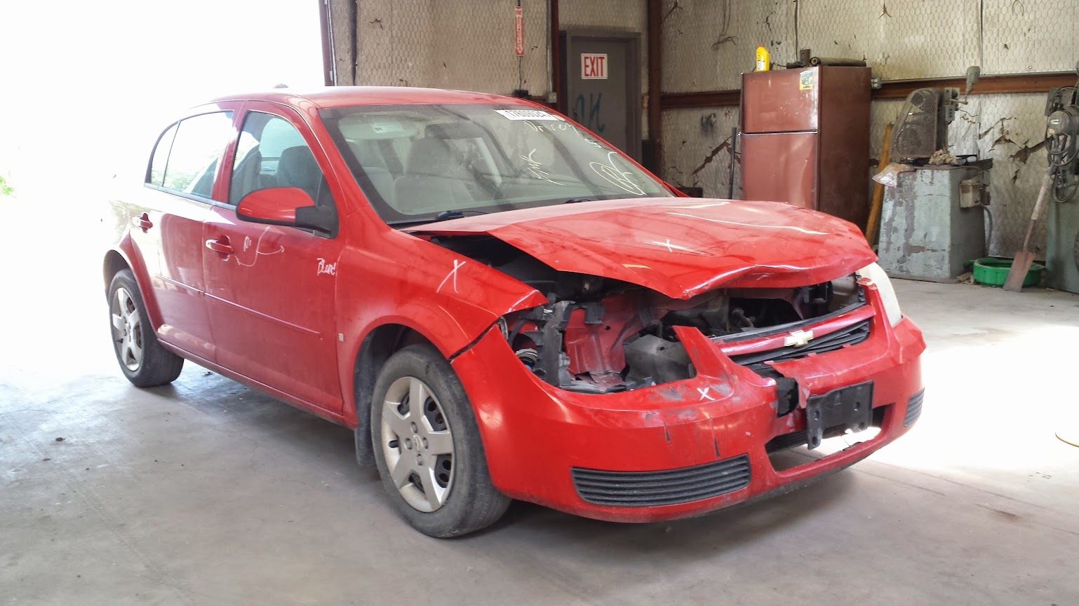
We drove to Fort Worth, picked up the donor, took it to our shop and immediately got to work stripping pieces from the nose to assess the damage further. We were happy to see that the subframe, which we planned to use on the Goblin, was still straight.
May 9 - Removing the powertrain and subframe
The next weekend we got the engine, transmission and suspension out as one unit connected to the subframe. We took measurements of the subframe to design our frame on Solidworks. Essentially, we are doing what Pontiac did with the Fiero. The subframe, powertrain and front suspension are being translated to the rear and our tube chassis will attach to the stock mounting locations of the subframe.

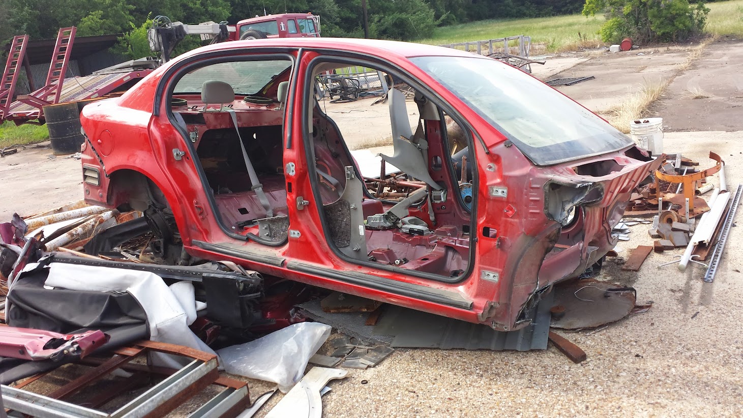
June 4 - Stripping the donor. Starting on the frame
Our spare time was split between house restorations, rebuilding a Baja Bug and working on the Goblin. In our limited time, we did finish stripping the donor car down to an empty shell.
After stripping the donor, we got to work designing the car on Solidworks. We started by drawing the subframe and building the model from there. We designed the chassis around the stock Cobalt seats and kept the wheelbase to around 95 inches. During the designing process, we kept in mind that anything we drew, we’d have to bend up ourselves. So to make things easier, each tube of the frame is bent on a single plane.
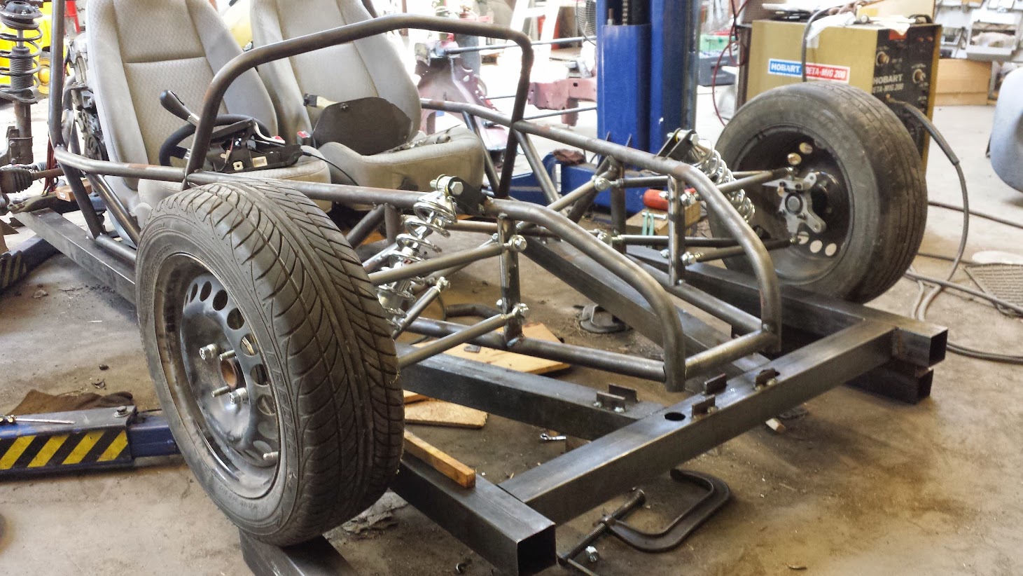
After laying out the frame on the computer, we used the model to make a template the same shape as the lowest rails of the frame. This template was use to weld together a jig to hold the tubing square and aligned to our model while the frame was welded together. Using this jig, we quickly got the basic frame welded. In the following picture you can see the jig under the frame.

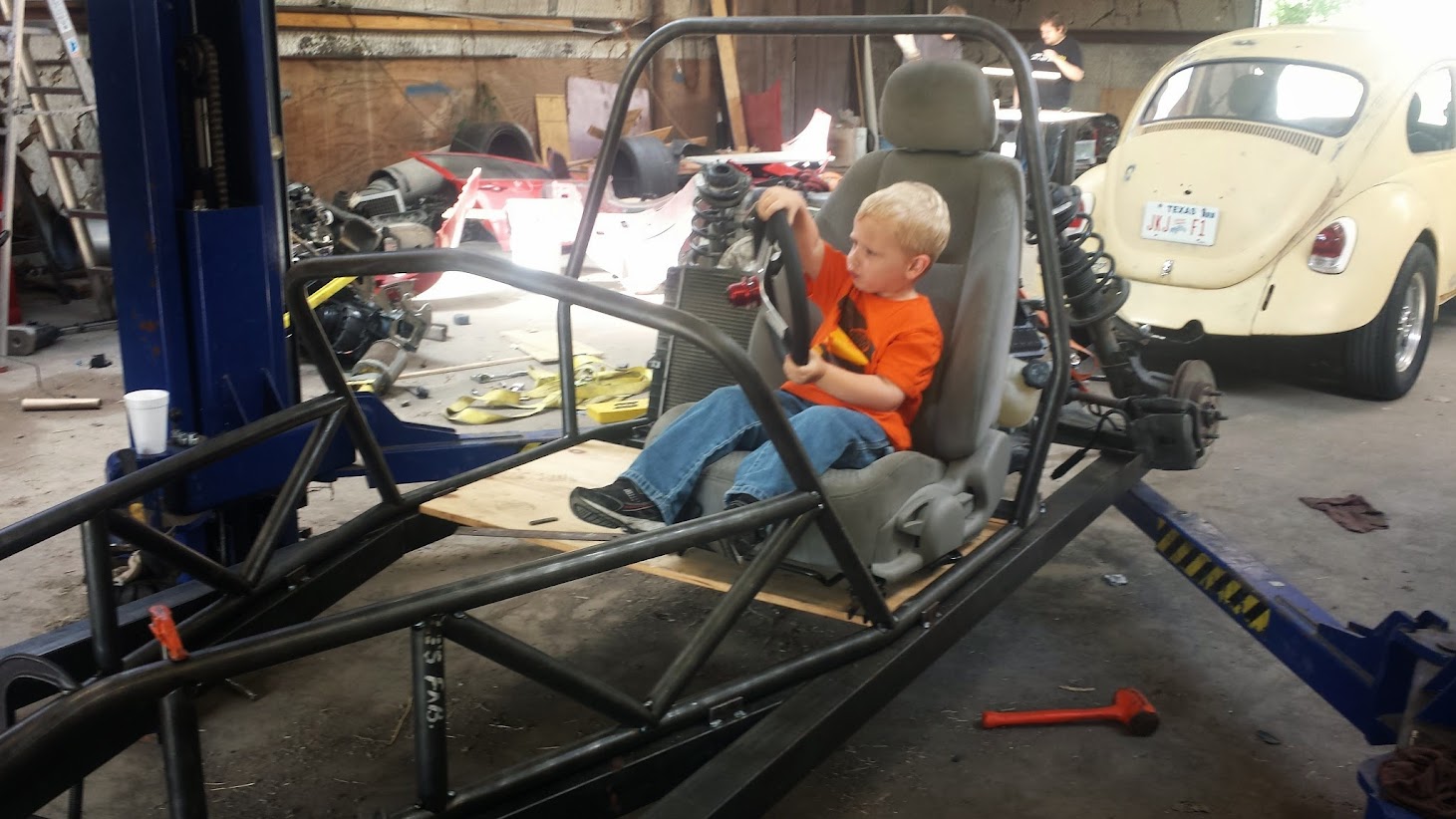
We then moved up, building the rest of the front of the frame. Jackson, my nephew and our future racecar driver, got a kick out of sitting in the car.
June 18 - Front suspension
We designed the front suspension around inexpensive coilovers we bought from Speedway Motors. This won’t be the last time we design and build the front suspension, so we did a little work to get a reasonable roll center but to keep things moving forward, we didn’t concentrate too much on optimizing the geometry. That will come at a later date.
June 23 - Rear suspension
So that we could dial in the rear suspension, we used adjustable rods to hold the strut towers in place. In the future, we will replace the rods with welded tubes to make the rear suspension rigid.
The stock springs had the suspension pegged all the way up, so to get down to a reasonable ride height, we cut one coil from each strut. This has the added benefit of increasing the rear spring rate.
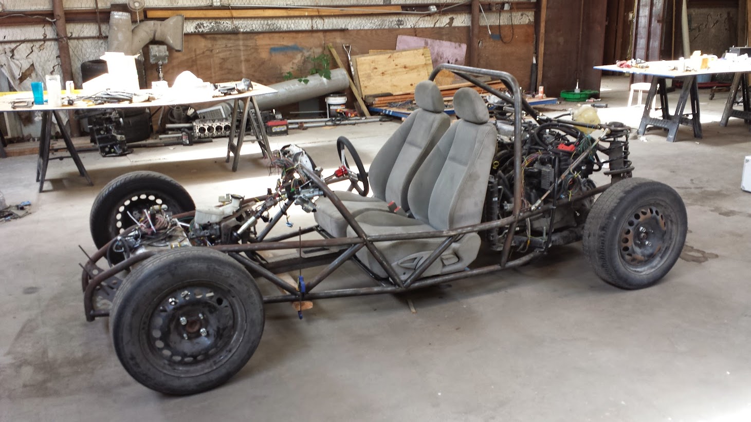
We also got the seats installed. They are very easy to deal with since they slip over a square tube in the front and bolt down in the rear. They are very dirty (and keep getting dirtier) so we plan on covering them when we are done.
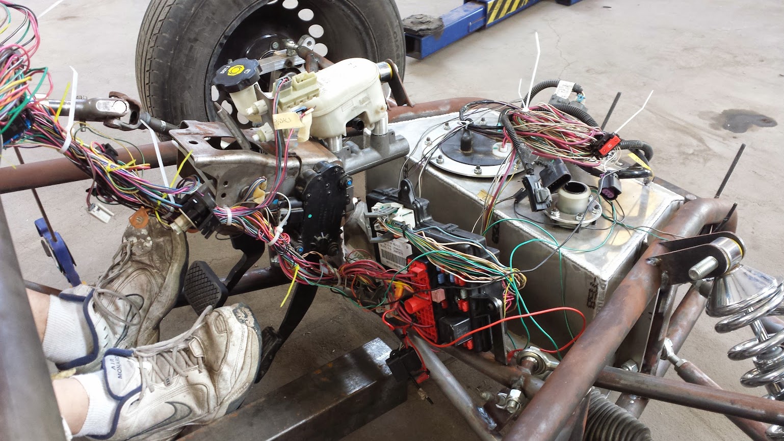
June 24 - Wiring
There is nothing quite as daunting as the sight of a Cobalt’s worth of wiring strewn across a table (well in this case two pieces of OSB on saw horses).

The task before us was to work our way through the wiring, eliminating systems that we would not be using and figuring out which wires would have to be extended to reach from the fuse block near the engine to the BCM at the front of the car. We took our time trying to make sure that after we extended, routed and connected it all, everything would work as planned.
Also, one of our goals was to make the extensions using only the wire that came with the Cobalt so that we wouldn’t have to buy any extra wire.
June 25 - Fuel tank
We purchased a 5 gallon plastic tank from Summit Racing but then decided to just fab our own tank. A custom tank would be beneficial for many reasons. First, it would be easy for us to make a tank that accepts the stock Cobalt fuel pump. Second, the tank could be designed to make better use of the space available for a tank. We ended up opting for a custom welded aluminum tank.
We started by drawing a tank on Solidworks that was a nice fit in the space between the front frame tubes. We then laid out each panel of the tank and CNCed them out of .125 inch aluminum.
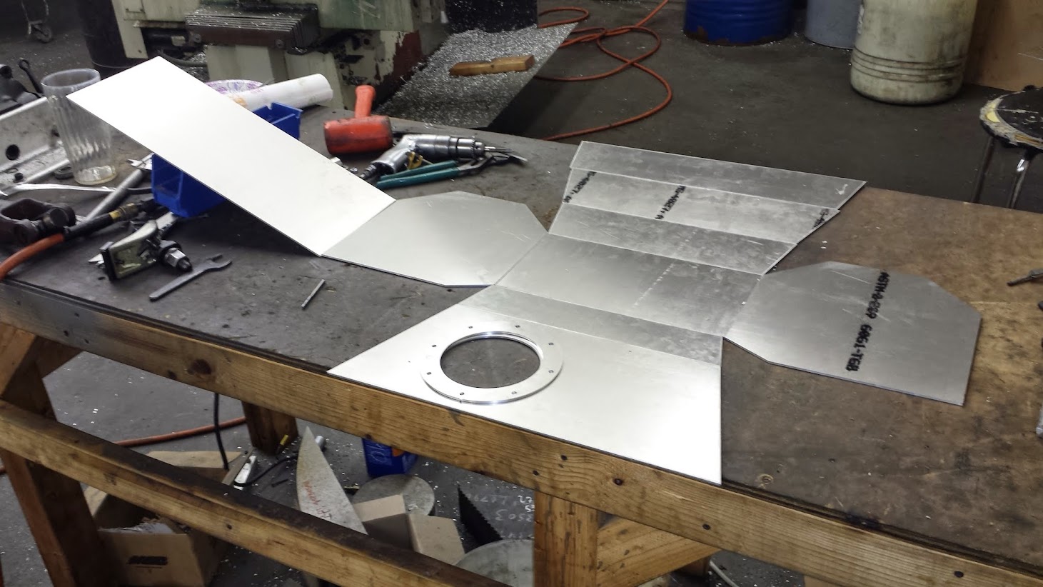
My dad tacked the tank together for a test fit. The tank fit great showing that our frame matched our Solidworks model pretty well.
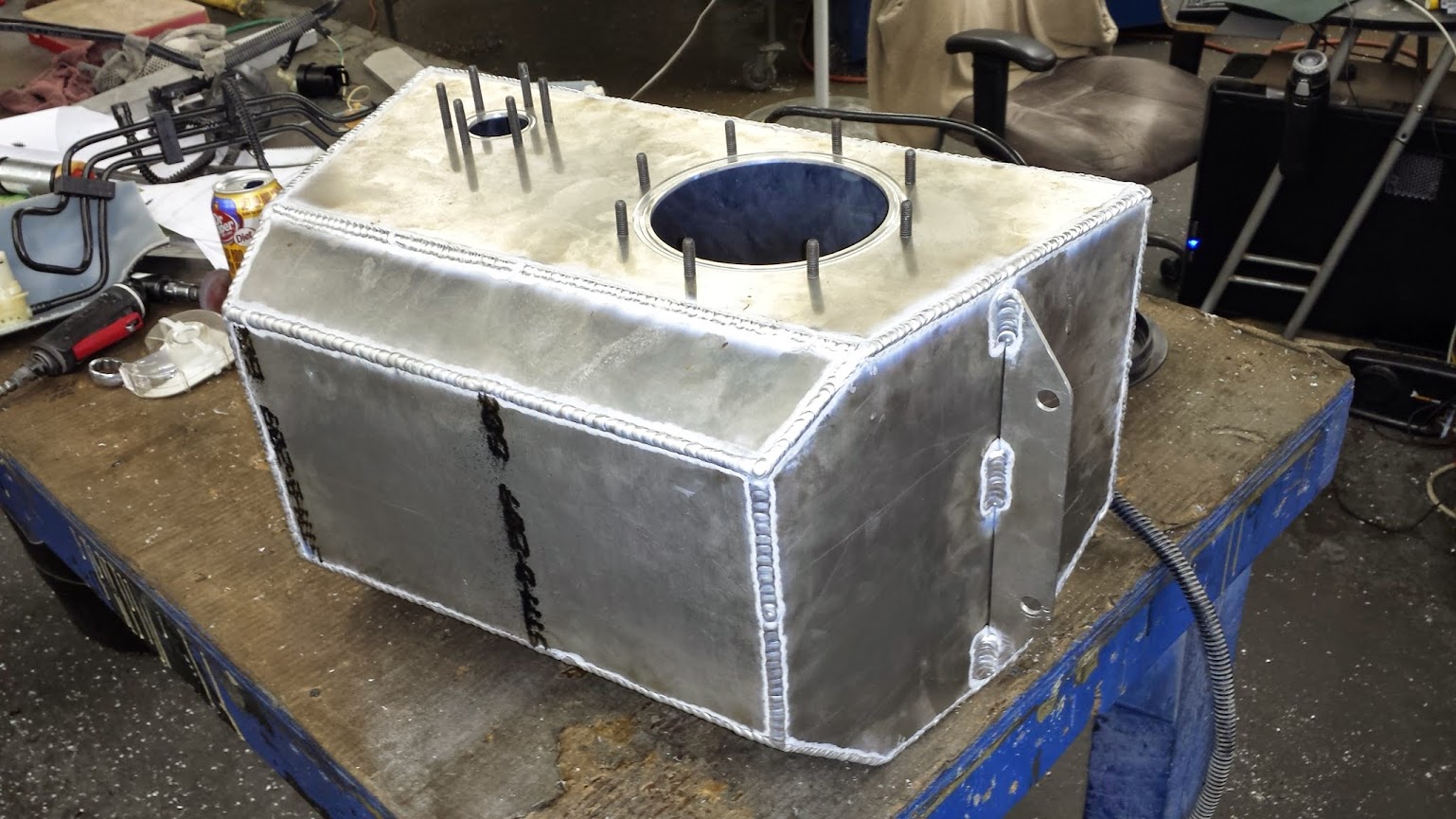
He then TIG welded all of the seams. The final steps were to add bolts for the Cobalt filler neck and pump to bolt on to and to install the pump tray down inside of the tank.
June 29 - Pedals and steering
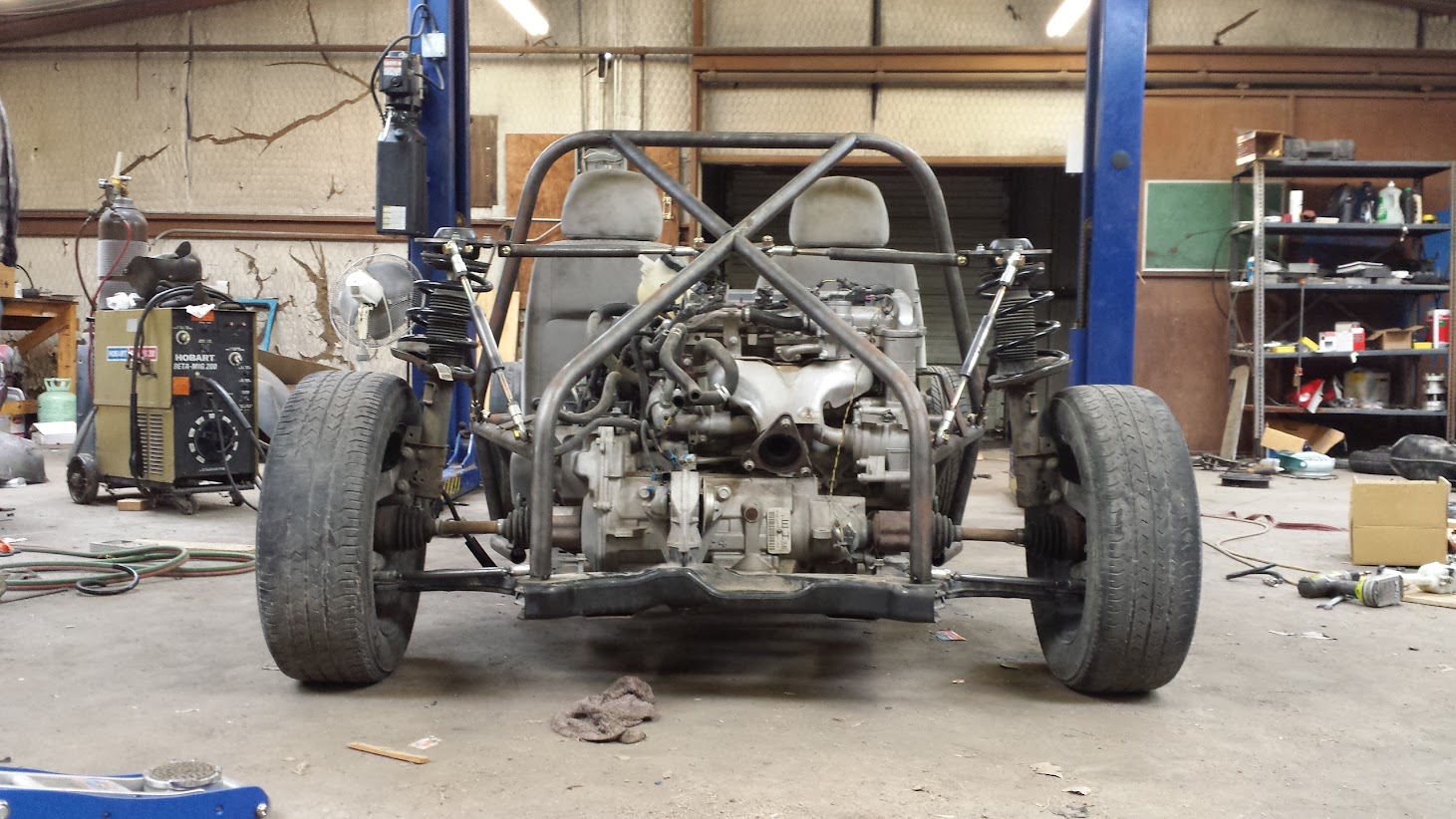
This picture shows how busy the front of the car was getting even before the wiring was run from the rear to the front.

Many things have worked out well from choosing the Cobalt as the donor car. Two of those are the pedals and steering rack.
With the throttle being drive by wire, we don’t have to route a cable from the pedal to the throttle body. Also, with a little creativity, we were able to use the stock master cylinder and brake reservoir.
Eliminating the brake booster required us to shorten the brake push rod. Also, the reservoir had to be turned around backwards or else it would have ended up poking out above the fiberglass nose we’ve drawn up.
Lucky for us, the Cobalt has electric power steering. We’ve eliminated the power assist (won’t need it with a light front end on a track car) and installed the Cobalt rack and pinion. Since the stock system is electric, we didn’t have to deal with deleting hydraulics from the rack.
July 6 - Wiring and gauges
We bravely pushed through the task of figuring out and installing the wiring. A large spinal cord of wires was routed through our tunnel to connect the engine fuse panel to the BCM, front lights and fuel pump. We were able to extend all of our wires using wire from the donor car.
In the following picture you can see how our structural cross brace is used to hold the BCM, pedals, suspension mounts, BCM and eventually will connect to the tunnel.
We had planned all along to use the stock Cobalt gauge panel. This will allow us to use the information panel that gives ambient temperature, fuel range, fuel mileage, coolant temperature, oil life and more. We also think it looks slicker than trying to install individual gauges.

Sorry for such a long post. We are just really excited to let you guys know what we are up to. I'll get the pics and text together for the next post and hopefully by the end of the week have more up.

That welding sure is pretty.

Wanted to post the same thing. Dad is a hell of a welder!

I have that same Hobart... I LOVE it!

But I want more now!!

nocones wrote: But I want more now!!

This is quite a family project! Would love to do something like this with my dad.

Wow dude. Nice work so far. I wish I had a project with my Dad at that age. I hope you guys are having fun. It certainly looks like it. Love the fab on the tank. Watching with interest. How much time (on the calendar) are we thinking for the rest of the build?

How many pedals?
It looks like two hydraulic reservoirs, but only 2 pedals.
In other words... Manual or autotragic?

Great project!
wvumtnbkr wrote: How many pedals? It looks like two hydraulic reservoirs, but only 2 pedals. In other words... Manual or autotragic?
4 door cobalt LS rental level special? I'm guessing automagic.

You can see the auto shifter sitting on the table in the 9th picture down.
Awesome project, assuming you will have a manual in there in the future.

Cool project, similar to the Midlana I am building. It looks like the front subframe from the cobalt bolts onto the rear of your chassis, very clever way to do rear suspension.
I know you said you didn't focus on front suspension geometry, but I would check bump steer with your steering rack and design, it can be dangerous if it has a significant amount, and the geometry that controls it is somewhat complex and it's unlikely that it just fell into place.
My dad says thanks for the compliments on his welding. Since starting the machine shop he hasn't spent as much time welding but I guess its like riding a bike.
It is awesome doing projects with my parents. They even let me start racing dirt track when I was 14. Here's the car we built back then:
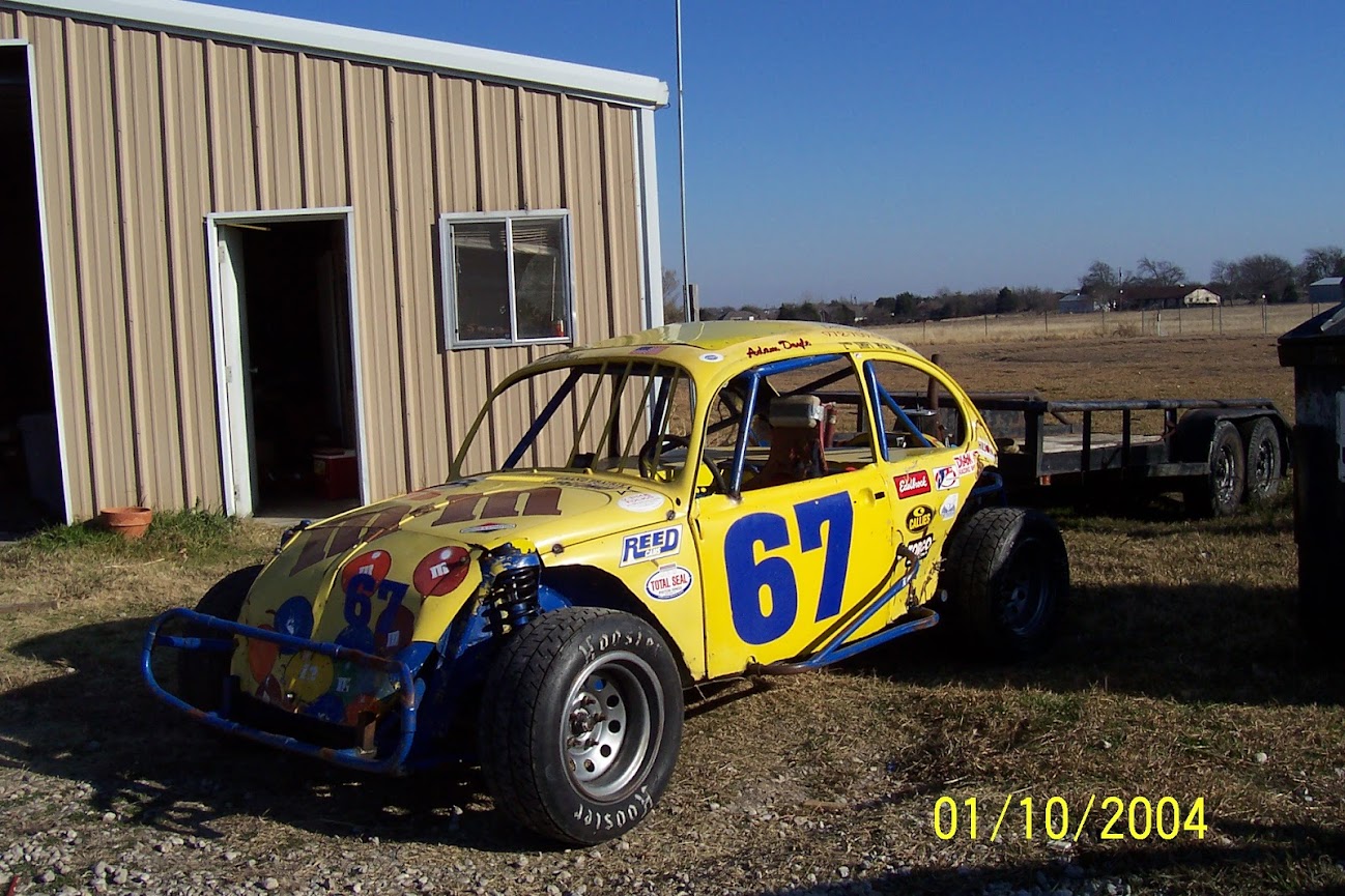
My dad raced it the year before I did. We both really enjoyed it.
As for the time left in the build, we estimate that it will take to the end of October to finish. We are still designing and building at the moment. After we feel like we have everything in the right place, we are going to disassemble the whole thing and weld out the chassis (its currently just tacked). At that time we will also clean it all up and paint it. Then we'll reassemble it.
Our donor was an automatic. It does appear to have been a rental at some point in its life because we found a spare key hidden in a bag under the trunk carpet. Apparently this is common practice for some rental companies.
We would definitely prefer to do a manual but this way the shifter and pedals were a little easier to deal with. Two of my brothers and I have stick shift 2009 Cobalts as daily drivers so perhaps in the future we could convert one or more of those. Mine only has 30k miles so it would be a great donor.

Cool project!
I like that you're using SLA suspension up front instead of sticking with struts.
With the original steering knuckles now at the rear, what are you using for front steering knuckles?
Are you going to do anything to correct the suspension geometry issues caused by running a front suspension in the rear? All the problems that cause Fiero owners swap out the early FWD-style subframes for the later clean-sheet '88 design will be present in the current configuration.
With the front suspension moved to the rear, anti-dive becomes pro-squat, and bump steer is backward, among other things. The bump steer issue may or may not be correctable by locating your fixed tie rod links at the rear. The stock suspension will have toe-out on bump which is stable at the front since it reduces the steering angle on the outside tire as the body rolls. In the rear, toe-out on bump increases the rotation of the car as the suspension loads -- not desirable!
We have studied the Fiero a bit. We will probably end up making something like the Held Motorsports bump steer fix. However, until then, we are going to attempt to find a sweet spot for the tie rod mount so that bump steer is limited.
One thing going in our favor is that unlike a production vehicle, our car doesn't need miles of suspension travel. With stiffer suspension we are hoping that the travel is limited, making it easier to optimize the compromised geometry.
We might be way off and end up with a big problem, but there isn't really anything we can't fix later after testing.
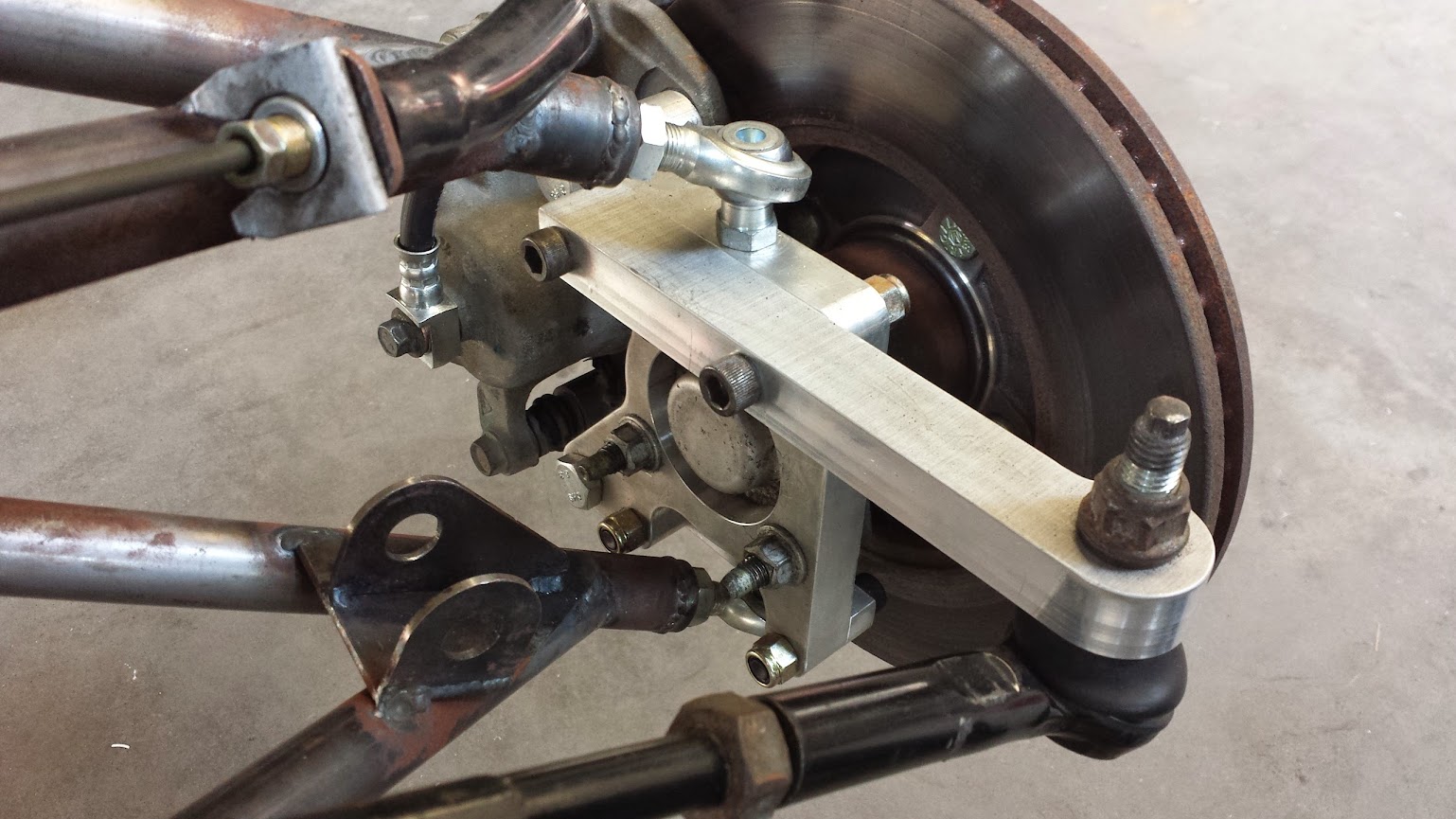
As for the steering knuckles, we made our own that accept the stock tie rod end from the stock tie rods. Rod ends top and bottom attach the knuckle to the control arms.
One very convenient thing about the Cobalt is that the wheel bearings are housed in a kind of hub that bolts to the car on one side and the wheel on the other (All I've ever seen is like my bug where the bearings slip onto a spindle). So we pulled the rear hubs from our donor and bolted them to our knuckles on the front. We also replaced the drums with stock front rotors and calipers so that we have disk brakes all around. More on that in a later blog post.
Oh, in reply to bgkast, we have noticed that our rack needs to be mounted a little higher to really limit front bump steer.
Thanks for all the feedback and keep it coming.
In reply to adoyle88:
This is fantastic. ![]()
Picking up where the blog left off:
July 9 - Brakes
Brakes on the rear of our car were easy. Every Cobalt has disk brakes on the front, so the rear of our car was set. All we had to do was straighten the original rear metal brake lines, reroute them through our tunnel, bending them as needed to fit the car, and then hook them up to the rubber lines coming out of the calipers.
The front was a little more challenging. Most Cobalts (all but the SS, I believe), come with drums on the rear. There is no possible way we would consider running drums up front so reusing the rears was not an option.
We considered buying aftermarket disk brakes for the front but they are very costly, and for a lightweight car such as ours, they’d probably be a little overkill. So instead, we went to a local salvage yard and got a set of front calipers and rotors from another Cobalt for a very low price.
It wasn’t too hard to fit the rotors to the hubs that we reused from the rear (had to machine a little clearance in the center) and we machined the caliper bolt pattern into our steering knuckles so they bolted right up.
The Cobalt uses one short rubber brake line going to the caliper. This works fine on the stock car, but not with our long control arms. What we did to get around this was to use two rubber lines. One connects from the caliper to a short metal line attached to the upper control arm. The second hose goes from the short line to the metal line fixed to the car.

July 14 - Starting the engine
We finished up enough of the wiring to take a shot at firing the engine up for the first time since removing it from the donor. Turning the key on, the gauges lit up but none of the other systems seemed to be doing anything. The fuel pump was quiet and the throttle wasn’t moving. The engine wouldn’t turn over either.
We initially thought it was the anti-theft system and tried a relearn procedure but that wasn’t the issue.
It turned out that in our hurry to wire just enough to get it started, we had neglected to connect a ground near the fuse panel by the engine. As soon as the ground touched, the throttle came to life and the fuel pump hummed.
We cranked it over and with a little bit of starting fluid, it fired up.
We had removed the radiator but figured it wouldn't really be a problem considering we didn’t plan on running it long enough to get hot. However, we had forgotten that this also meant that the transmission cooler lines were disconnected and they were conveniently aimed directly at me. ATF belched all over my legs, down into my shoes and on the lower part of my shorts.
It wasn’t a big deal though. To have a running engine after cutting, extending and routing wires was awesome even with me being drenched in ATF.
July 16 - Shifter install and first drive
We really wanted to use the stock shifter linkages and cable even though the engine was now behind the gear selector. The cable comes out of the front of the shifter box so the first thought was to loop the cable and send it to the rear. However, this just wouldn’t cut it. First off, it would look ridiculous having a looped cable and secondly the cable wasn’t long enough anyway.
Instead, we made a little arm that installs in the stock shifter and extends down below the shifter box. This arm has a bolt on each side of a little channel that slips over the stock shifter arm. We used the bolts to give us room to adjust the arm after installing the shifter.
We then made two steel mounts. One was a simple plate that welds to the tunnel and has bolt holes. The other was a welded together assembly that has an extension to hold the stationary tube that is wrapped around the cable. Our extension was designed to hold the tube the right distance from the pivoting arm so that we get full cable travel and is short and tight enough that we can slide it down in the tunnel during installation.
With the shifter extended down into the tunnel, we don’t have to loop the cable. The extra length provided by not looping is enough to have the cable reach all the way back to the transmission.
Somehow I did not take any photos of this and I really wish I had because it would make it a lot easier to understand what we did. However, I do have the models of the pieces we made. Here’s a screen capture of them. The extension pointing toward us goes toward the back of the car. The top plate is welded to the extension and the lower plate is welded to the car. The extension slips down through the lower plate.

In a couple of weeks when we disassemble the whole car, I’ll be sure to get lots of pictures.
Even though the chassis was only tacked together, we couldn’t wait to take a little drive. We put in the damaged radiator (mostly just to keep ATF from spewing out) and drove the car out of the shop.
We only did a few circles in our parking lot before putting it up, but it was neat to have the car drive on its own power.

When my brother and I solved the bump steer issue with the riviera powered toyota truck (swapped front drive to rear of truck) we built rods same length as lower control arms and mounted same plane. Reduced bump steer to 1/8" overall.
In reply to stan_d:
What size is the lower rod end? Unless its a high quality 3/4" this will end poorly. That ball joint will see a lot of force sideways on the ball and bendomg the shaft. These are 2 things rod ends suck at. A largr enough rod may survive but replacing with a proper automotive lower ball joint or a sperical bearing will save repair time in tge future when it fails.
Im not really a rod end side loading alarmest. I think the rest will be fine. That one i question.
In reply to nocones:
That's a good call, and he's already got one balljoint in there. Just buy two more and have at it.
3/4" rod ends are now ordered and on the way. Thanks for looking out for us.
The ball joint you see in the photo is the stock rod end from the donor car's steering system. It was pretty easy to cut the taper and put a nut on the backside of the steering arm.
As to limiting bump steer, I know that as little as possible is the goal but does anyone know a rule of thumb for an acceptable amount of steer change vs. amount of suspension travel?

![]()
![]()
![]()
![]()
![]()
![]()
I would't be comfortable with more than 1/8 inch or so over the full travel.
bgkast wrote: I would't be comfortable with more than 1/8 inch or so over the full travel.
You should be able to get essentially zero. My Dad used to get close to zero with old sloppy drag cars. Surely you can do it with this.
You'll need to log in to post.


