So, I have this car in my garage now with the engine pulled and the engine bay mostly stripped. I want to retrofit a steering rack in place of the old box and center link, and step one of that process is going to be measuring and modeling the factory suspension and steering so I understand what I'm starting with. Trying to be realistic here, I'm not going to build the perfect MacPherson strut front end, I just want to avoid making it worse than what I started with, and make it better if I can. Here's what I'm looking at right now:

I've got the distance between the mounting points for the lower control arm bushings labeled above. The control arms aren't perpendicular to the body/frame; they're swept back, so the bolts that go through the bushings are 22" apart on the front of the crossmember, and 20" apart on the rear. For simple 2D modeling purposes, I can just treat this like they're 21" apart, right?
If anyone has any advice for taking the rest of the necessary measurements, I'm all ears. I did a rough first pass, but some of the dimensions between parts are tough to get very accurately, because other parts are in the way.

I think that the 21" dimension should be good.
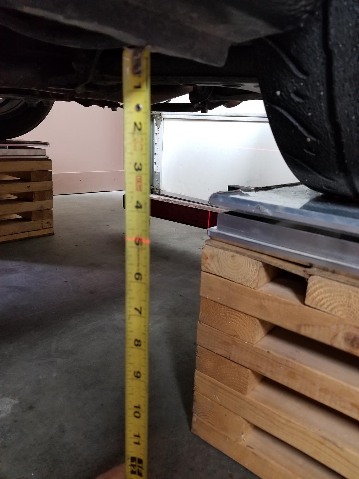
When I measure a chassis for modeling or just setup a car I put it on cribbing that's shimmed so that the tops are level.
Then I setup my laser level on a post with the vertical line at the centerline of the car and the horizontal at the top of the cribbing or the scales if I'm using them, whatever represents the ground.

Then I can get under the car for easier measurement. I measure off the centerline to the component, a plumb line or a framing square (whatever is most convenient) to get left/right measurements and down to the horizontal laser line for vertical. I'm checking ride hight in the picture below.

If I need to access ball joints or something that's inside the wheel I measure from the centerline of the hub to the ground reference, jack the car up on that end (or maybe just that corner), pull the wheel and spring(s), lower the car down to ride hight, raise the suspension till the hub is at the correct hight and start taking measurements.
It's worth it to take the time getting the car configured for accurate measurements. If you don't then you can't really trust any of the analysis. Garbage in garbage out and all that.

dps214
Dork
12/16/21 6:18 p.m.
Are you actually looking to mess with suspension geometry, or just want to get a reasonable steering rack setup?
If the latter, you mainly want the tie rod to be the same length as the control arm, the two links to be parallel in the vertical plane and pretty close in the horizontal plane, and ideally as close to in line as possible (some or all of that may be limited by steering knuckle geometry though). If you can get pretty close to that, you're like 90% of the way there and it'll almost certainly be better than the stock linkage setup.
If you're looking to actually re-engineer the suspension, then there's a billion different variables to consider.
In reply to APEowner :
Awesome, thanks! That laser level setup is exactly the kind of thing I was looking for. I was picturing something involving strings.

In reply to dps214 :
As far as suspension geometry goes, I mostly just want to understand what I'm working with. On other cars, I've only ever done simple alignment changes...okay, I admit I've cut a few springs, too. So, I think it would be a good learning experience for me to measure everything, and just try to check Mitsubishi's 40 year old work myself.
If the roll center ends up way underground at a lower ride height, or there's some quirk in the stock geometry that would be easy enough to fix, I'll at least know about it. This is the first project I've had where really messing with the suspension feels like fair game, but since I'm also in the middle of an engine swap, I can't fall down a billion-variable rabbit hole right now, as enticing as it may be. It's a good time to take measurements while everything else is out of the way, though, and I need a lot of those measurements to try to get the steering right anyway.
For the steering, if I just want to match the width of the stock center link, I need a rack that's 20" between the inner tie rod pivots, which I haven't been able to find. There are lots of racks that are just slightly longer, and there's also the option of getting a new custom rack, or getting an existing rack narrowed. I'd prefer to use an off-the-shelf part if I can, so I'd like to play around with different rack lengths and heights to see what I can come up with.
Maybe I can't achieve zero bump steer, but if I can get an acceptably small amount of bump steer in an acceptable direction in the actual range of usable suspension travel, that might be good enough. If I can't find "good enough" with an off-the-shelf part, then I'll have to go the custom or narrowed rack route.


