
Hello All,
I've been having some fun with an STMPro speeduino ecu in my Pinto for a couple months now. I've hurt one of the output chips a couple times, but had success replacing the chips. Now I am in a situation where I do not have a response from my tachometer. It has worked with this ecu in the past, however the signal originates at the same chip that I've had other problems with. So to test the output, I've hooked it up to a friends ancient engine analyzer, my timing light with rpm lead, and tried assigning new pins to the tach output. So far I have not been able to read a signal.
I borrowed a friends oscilloscope to try to read the signal, but I am not having success. While discussing with a friend, we realized that the tach signal is probably just a switched ground, and may not provide a reliable signal if the other scope probe is grounded. So this leads me to my question:
How does one test a tach/rpm output from an ECU such as speeduino with an oscilloscope or multimeter? I'd like to have confidence in my troubleshooting before replacing the chip again, or buying another tach.
Picture for attention:

To follow up on this here is an excerpt from my build thread. Hopefully this will help the next person searching the internet for how to test a tachometer output with an oscilloscope.
Then I learned about pull up circuits. Pretty genius actually. For those that don't know, here is a diagram:

The idea is to use a large enough resistor on the power source to reduce the current enough that the switched ground can easily "pull down" the Vout to ground when activated. When the switch is open, the current is enough to "pull up" the voltage to equal the power source.
To tie it all together, the reason my spare low current output didn't work was that there was no power source in the circuit. The output is a switched ground, and the tachometer is expecting a square wave of 12V/0V. Without a power source the output is a 0V/0V square wave (no signal). Once I moved over to one of the high current outputs (small connector pin 12, Arduino pin 28), I used a 10k Ohm resistor and tapped into the hot side of the usb charging port for power. I also added a .5A fuse because I'd really like to be done soldering on this ECU for awhile.

This allowed me to connect the positive oscilloscope probe to the Vout wire (signal wire to the tach from the ecu output), and the ground probe to chassis ground, and read a nice clean square wave on the screen.
In reply to Shavarsh :
I had to do this even with a Megasquirt box when using its tach out. It just switches a ground, it doesn't supply power. A tach doesn't supply power on its input wire (otherwise an ignition coil may not work) so I added a 1000 ohm resistor between my tach's power and signal wires.

In reply to Pete. (l33t FS) :
That's a great way to get it done. I'll keep that in mind.
Depends on the circuit used, but even a processor output you should be able to see on a scope. The std ms tach output uses a 1k pullup to 12v from a low power npn transistor. Likely this, along with many other things are copied by the speedy guys 

In reply to Paul_VR6 (Forum Supporter) :
Curious... I have a 3.57 board from about 10ish years ago, it definitely didn't have a built in pull-up on the tach output.
Or maybe it did but it fried in the years between installing the unit, and using its tach output. I'm not sure how inactivity can damage a resistor, though.
3.57 did not have a dedicated tach out, you'd have to build it. The circuit above you would have to build on the DIY style boards. It's included on a micro, ms3 with 3x board, MS3 Pro etc.
The built in pull up is also included on the STM Pro speeduino, selectable between 5V/12V on the tach output. I suspect I've damaged that output. That's why I've installed an external pull up on a spare output.
In reply to Paul_VR6 (Forum Supporter) :
Good to know. I'd never run into this issue with a Pro before.
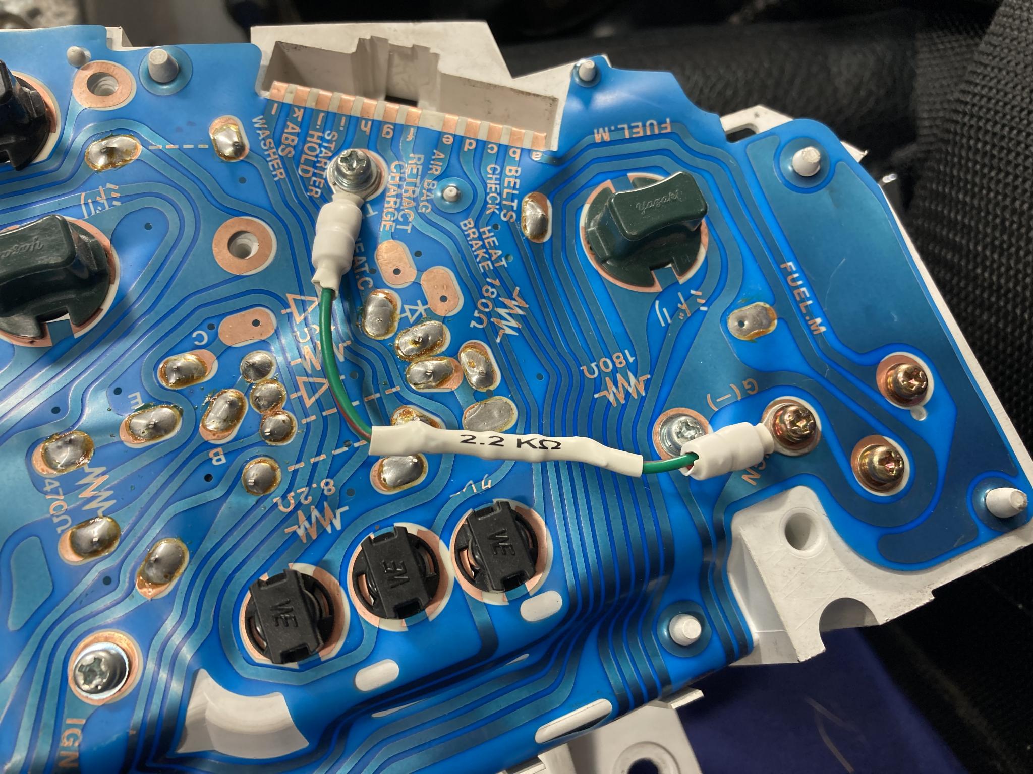
I had to add a 2.2k resistor to the factory Miata tach to allow it to be driven by a GM ECU.
Does the Speeduino have a test mode where you can force the output into an on and an off state? If so, you can check the voltage in both states with a multimeter.


