I'm interested, I'd like to do the same for my Corolla some day, and I may end up building a set of custom knuckles for a different car further into the future.
Well 4.5 months after the last post I have a bit of an update.
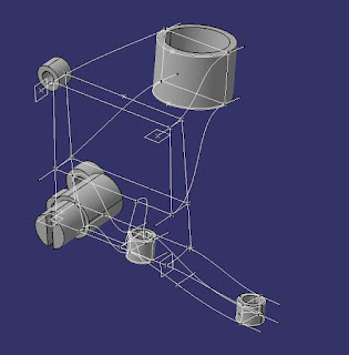
To paraphrase slippery this is one berkleyed up part. What I received was a bunch of "tubes" which were basically the outer diameter of the mounting point along with the hole and it's correct taper, from this first image the solid shapes are basically what I received from slippery. At first blush this looked easier than I found it to be.
No 2 holes (save for the dust shield and brake caliper mounts) lie on the same plane, this makes it a bit of a chore to try to stitch together into some sort or solid object. Ultimately surfacing winds up being the best option for this as it's the easiest way to tie things together in 3D space. You can see my skeleton starting to take shape here as well:

A bunch of surfaces and convert to solid commands later and I wound up with this. Note, this is revision 5. Each time I scrap the model and start over I've learned a few different commands or found a better order of operations to make things more logical. In this rendition I've also moved the wheel bearing upwards creating a 15mm drop spindle, and I've deleted the stub axle for the e46 press fit bearing in favor of an e92 m3 bolt on wheel bearing assembly which would be easier to change at the racetrack with basic tools.

To get a sampling of how much I'm learning each time I make a new revision to this knuckle? this is my first revision:
Now that I am starting to feel comfortable with making surfaces my next step will be attempting to build this in a manner which could potentially allow for the part to actually be built. After I finally get a revision that "looks" good it will be time to start on some FEA.
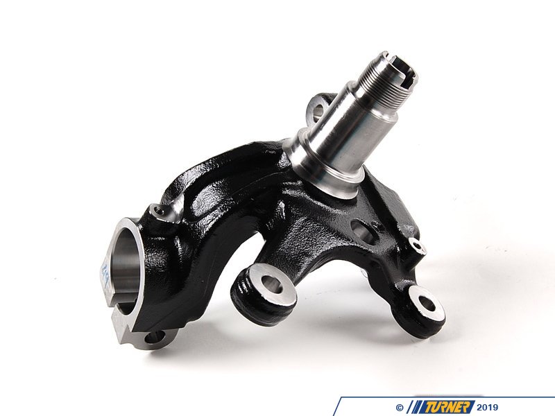
Lastly for those perhaps not familiar with the e46 kingpin:

Good stuff! Your latest design looks quite sturdy, I'd say FEA is overkill, but it would be entertaining and educational to read about you doing it ![]()
The only potential improvement I can eyeball is that maybe you should curve the webbing further into the background direction on the caliper mounting points, so that the metal holding them on is beefier, like this (additions in green):

You could increase the size of the hollowed-out pocket to offset the weight increase.
GameboyRMH wrote: Good stuff! Your latest design looks quite sturdy, I'd say FEA is overkill, but it would be entertaining and educational to read about you doing itThe only potential improvement I can eyeball is that maybe you should curve the webbing further into the background direction on the caliper mounting points, so that the metal holding them on is beefier, like this (additions in green): You could increase the size of the hollowed-out pocket to offset the weight increase.
ohh good call! I'll explore adding that for this next revision, I've been slowly sifting through the web for images of other knuckles and cherry picking ideas off them (this is harder lately with the demise of photobucket)
A couple additions which I'm wanting to explore on future revision, turning the brake caliper holes 90 degrees would allow for monoblock calipers (like the Brembo's I run) to be a direct bolt on affair without needing to run an adapter bracket similar to the design seen here:

The other idea with regards to machinability would be to make something multi piece where the lower balljoint/tie rod are machined from one piece while the upper is another piece, this would allow for playing with different locations of both above mentioned components relative to the shock/tire. I see many aftermarket spindles which due this and from a machining standpoint it's likely easier as well. I just personally prefer to have as few bolts to check for tightness during pre race inspections as possible.
Here's an example of such a design:

You could also put the steering arm on a removable piece so you can adjust steering speed & travel, but that carries the same maintenance downsides.
YOu could generate a rough casting model and have it cast by a rapid prototype company. A partial DIY method would be to 3d print a rough cast model. Use that to cast some sand molds then use the sand molds to cast the part. But finding someone willing to fire and pour your metal of choice can be difficult.
Depending on the material it might just end up cheaper to throw a billet into a 5-axis and just let it go at it. Especially if you can catch a machine shop with a lull due to summer shutdowns of various factories. They would probably like you to have the program mostly completed for them. Then again it might be possible they just want the CAD model and will build from that.
You might want to use bolt on steering arm and caliper brackets so that you can make the spindles the same for both sides of the car. If you're casting or hand machining them it'll almost certainly be cheaper that way. If they're CNCd then the cost difference will be less significant.
FEA is never overkill. Do it. Or give me the cad file.
Even if you don't have really accurate outputs from FEA (more common than most people think), it does a great job of highlighting where the high stress points will be, which are always good things to mitigate.
excellent suggestions!
Those pretty well line up with the image I had shown where the lower control arm mounting point/tie rod/steering linkage are on a seperate piece for changing geometry.
I'll have to give some more thought to if/how the main piece could be identical on both sides for ease of machining but since the strut mount tips both inwards towards the center of the car as well as rearwards for caster, I'm not sure that will be feasible without braking the hub into an additional piece at which point it might be diminishing returns.
ProDarwin we agree on FEA, the math for figuring out loads will be the interesting part as this is a bit different from the usual things I run FEA simulations on.
You'll need to log in to post.