1 2 3
Leafy
Leafy New Reader
9/30/13 9:37 p.m.
dragoon119 wrote: In reply to mblommel: Where? Below the engine compartment, tunnel, firewall, and rear roll bar? Is that where triangulation is needed more?

I couldnt quite tell you because I dont know where your suspension pickup points are. And that 2nd triangle that goes to the middle of the tube on the front is pretty much just ballast since it goes to the middle of the tube.

Seriously, chassis design is a simple game of connect the dots. No tube should meet another tube in the middle (unless its just passing though). And follow the load paths where possible, which is normally not very possible at all since there's normally an engine and driver in the way. Tubes are weak when you push perpendicular to them in the middle, they're strong when you push or pull on them lengthwise.

dragoon119
dragoon119 New Reader
9/30/13 10:53 p.m.

In reply to Leafy:

Currently working on that, I am also reducing the size of some of the frame rails that people are say are too large.

I will have the mounting points clearly established but the transmission is a different manner. I have been looking for a dimensions for the Ay6- 6 speed tranny for months and nothing. I need to know if it has similar mounting points to a T-5 trans because depending on dimensions or costs I might swing either or.

Should have updated pics and Step model up in about an hour. More Triangulation Less tube size More strategically placed bracing Underway

Oh yeah btw, I had planned to use the windshield as a roll over bar so would it actually be wise to lower the firewall size to 2x4?

dragoon119
dragoon119 New Reader
10/1/13 10:42 a.m.

Alright guys I did some modifications to the frame.

I lowered the central tunnel rails to 2x4. I kept the firewall and rear section (Sorry I'm am really exhausted and can't identify the proper meaning at the moment.) at 2x6. I added more bracing under the front of the engine bay and have the load going toward the edges of the passenger compartment in case of a crash. I've finished half of the rear section and would like opinions on how it looks to you all.

What I am trying to go for is an X frame like the S2000

But on a lower section of the vehicle like the Lotus Elan

I want the windshield to double as a roll bar, so I use 2x4 on that section going into the 2x6 frame acting as a Firewall/footwell.

dragoon119
dragoon119 New Reader
10/1/13 10:53 a.m.

Heres the revised chassis

dragoon119
dragoon119 New Reader
10/1/13 10:54 a.m.

In reply to Leafy:

Leafy, I should have a model up after work, which will be pretty late.

nocones
nocones SuperDork
10/1/13 11:29 a.m.

What kind of educational background do you have? I'm not intending to be mean but given some of the comments you have stated I suspect this may be a bit beyond your current skill level. That for sure does not mean you can't learn. That's what learning is for.

Your starting at the wrong spot if you do not have a functional suspension design.

My car building recipie goes like this:
1. determine what Drivetrain (Front, Mid, Rear engine, FWD, RWD, AWD) you are going to use.

  1. Identify a power goal to select an engine and transmission.

  2. Do a rough layout of key components to determine rough weight distribution targets (Include engine, trans, occupants, fuel tank and any other heavy items you know the weight of. Assume the chassis weight and that it's near 50/50 your just getting close here). Here is where you determine Track width (Driven by expected CG height), and Wheel base (Driven by desired Weight distribution).

  3. Select Tire sizes (Width, Overall Diameter, and Rim diameter) based on HP, Weight distribution, and drive configuration. You need to consider required brake system performance because it will drive your Rim diameter.

  4. Suspension. Now things get interesting. It's time to design your suspension. No 1 solution works and there are NUMEROUS entire BOOKS about this so everything I say from here is VERY condensed from my experience the design of 4 competition vehicles. I always start at the front. Assuming you’re running a double A-arm or multilink type suspension the first choice I feel you should make is what your goal for Kingpin inclination and scrub radius is. This will determine the location of your lower ball joint and will be used to drive the rim offsets. Make sure you can get rims of the offset you want. I always design for close as possible to 0 KPI with minimal scrub radius. Next chose a camber coefficient that you want and a RC height. These two numbers basically coupled to the Lower Ball joint location dictate the path that your A-arms can lie on. The Camber coefficient determines your VSAL. This also dictates where your load paths into your chassis are. You now simply draw your front layout and determine the highest position possible for the Upper ball joint that will be dictated by your rim diameter. The only big things left are determineing actual A-arm lengths (Fix the inner pivot locations) as well as select a Caster and spindle offset (Determine Trail). Relative A-arm lengths will have an impact on how much your roll center moves as the suspension travels and how much your VSAL changes. Determine how you are going to suspend the car (Push/Pull rods, bellcranks, direct action shocks). You also need to design the steering. That’s actually fairly easy. Select a Ackerman percentage determine where the Steering links go and their length (Driven by desired steering ratio and available steering rack ratios) and determine their locations on the car. The outer endlinks are determined by the ackerman ratio and can be at any height provided the inner pivots are at the correct location. Inner pivots should be on a line between the upper and lower inner A-arm pivot and create a line with the outers that intersects your static VSA. This determines your rack width and height. Generally you will have a fixed rack width so this will driver your rack height (Or space constraints will) and the Upright side will just be determined from this location.

Rear suspension thankfully is easier. It doesn’t turn so KPI/Caster/Scrub Radius are much less important. Basically you follow the recipie for the front otherwise but you need to consider avoiding drivetrain components and anything else that will get in your way. I run much shorter VSAL in the rear because you can’t gain camber through caster (usually around 1.2x track width).

  1. Finally the Chassis. You now know where everything goes (engine, trans, fuel tank, people) and where your road forces will act on the CG (Suspension design). You can finally design a chassis. Basically play connect the dots with straight lines, avoid things you can’t put lines through, make triangles and I like to include a SCCA/NASA legal Cage appropriate to the weight of the car I’m building. I figure I want to use my car in anger and these guys are who I would most likely be looking to do that with. If your going to build, build to some sanctioning body so you don’t have suprises later.

Notice how low on the list this is. I love making concept sketches of cars and chassis but I’ve done this 4 times and have a good idea of what a suspension will look like. It sounds like you are still very early in the game and are getting ahead of yourself.

After the chassis things get fun because you get to update your weight spreadsheet and start to determine spring rates, ride frequencies etc. Obviously the inclusion of OEM off the shelf components fix some of the dimensions and freedom you have. This is sometimes good because a true clean sheet design is Insanely time consuming and difficult. Saying I’m going to use a Miata upright or MG steering rack fixes some dimensions and makes your job easier.

Good luck and take things as constructive. Your primary goal should be to make something safe and have fun. It’s a crazy road your headed down so I wish you luck.

nocones
nocones SuperDork
10/1/13 11:39 a.m.

BTW holy wall of text nocones.

Leafy
Leafy New Reader
10/1/13 11:41 a.m.

Excellent points. And all this book talk reminds me, Racecar Vehicle Dynamics by Milkman is one of the 4 bibles. The other 3 being Robert Norton's 2 books, and the Machinery's Handbook.

There's a lot to consider on the suspension, never forgot to overlook anti-dive and anti-squat. Its so complicated thats why I suggested just stealing miata parts or any other well handling vehicle as a base to build a tube frame off of.

Knurled
Knurled UberDork
10/1/13 11:52 a.m.
dragoon119 wrote: In reply to Knurled: I put those in for side impact protection so I guess they are not needed?

Side impact protection comes from the sides, not the floors.

Really, if you're building a small open-top car, side impact protection is kinda moot. Unless you're wearing a harness and are strapped into a HANS-rated seat, your head is going to meet the other car's hood...

Regarding frame sizes, bear in mind that the vehicles you're modeling after are made out of 16- or 22-gauge steel, meaning .060"-.040" thick.

ransom
ransom UberDork
10/1/13 12:47 p.m.

I'd also recommend Allan Staniforth's Race and Rally Car Sourcebook, which has a lot of practical info and is very readable. It does, however, practically refer back to the evolution of the author's single-seat racecar, so the primary focus of examples is a little different to what you're working on.

I like that Staniforth is very encouraging, but as nocones points out, I suspect there's a fair bit more research to do to guide your considerations before you start picking tubes and where to put them.

Adrian_Thompson
Adrian_Thompson UberDork
10/1/13 12:53 p.m.

Holy awesome post Nocones

nocones wrote: My car building recipie goes like this: 1. determine what Drivetrain (Front, Mid, Rear engine, FWD, RWD, AWD) you are going to use. 2. Identify a power goal to select an engine and transmission. 3. Do a rough layout of key components to determine rough weight distribution targets (Include engine, trans, occupants, fuel tank and any other heavy items you know the weight of. Assume the chassis weight and that it's near 50/50 your just getting close here). Here is where you determine Track width (Driven by expected CG height), and Wheel base (Driven by desired Weight distribution).

I’d say his plan is fairly obviously Front/Rear. Also assuming this is fun road/track/toy I wouldn’t get too stuck on 50:50 weight distribution, surely anything from 40:60 to 60:40 is fine. Most ‘7’ end up with a rear weight bias anyway. I’d say his weight dist. is going to end up where it ends up depending on his donor parts and can be measure later and used for initial ride frequencies?

nocones wrote: 4. Select Tire sizes (Width, Overall Diameter, and Rim diameter) based on HP, Weight distribution, and drive configuration. You need to consider required brake system performance because it will drive your Rim diameter.

Again I’m going to swag that this is 90% determined by his donor, as in 90% of Miata based cars end up with off the shelf 15x6 or 15x7 wheels and 195-225 section tires as that’s what’s cheaply and easily available.

nocones wrote: 5. Suspension. Now things get interesting. It's time to design your suspension. No 1 solution works and there are NUMEROUS entire BOOKS about this so everything I say from here is VERY condensed from my experience the design of 4 competition vehicles. I always start at the front. Assuming you’re running a double A-arm or multilink type suspension the first choice I feel you should make is what your goal for Kingpin inclination and scrub radius is. This will determine the location of your lower ball joint and will be used to drive the rim offsets. Make sure you can get rims of the offset you want. I always design for close as possible to 0 KPI with minimal scrub radius. Next chose a camber coefficient that you want and a RC height. These two numbers basically coupled to the Lower Ball joint location dictate the path that your A-arms can lie on. The Camber coefficient determines your VSAL. This also dictates where your load paths into your chassis are. You now simply draw your front layout and determine the highest position possible for the Upper ball joint that will be dictated by your rim diameter. The only big things left are determining actual A-arm lengths (Fix the inner pivot locations) as well as select a Caster and spindle offset (Determine Trail). Relative A-arm lengths will have an impact on how much your roll center moves as the suspension travels and how much your VSAL changes. Determine how you are going to suspend the car (Push/Pull rods, bellcranks, direct action shocks). You also need to design the steering. That’s actually fairly easy. Select a Ackerman percentage determine where the Steering links go and their length (Driven by desired steering ratio and available steering rack ratios) and determine their locations on the car. The outer endlinks are determined by the ackerman ratio and can be at any height provided the inner pivots are at the correct location. Inner pivots should be on a line between the upper and lower inner A-arm pivot and create a line with the outers that intersects your static VSA. This determines your rack width and height. Generally you will have a fixed rack width so this will driver your rack height (Or space constraints will) and the Upright side will just be determined from this location. Rear suspension thankfully is easier. It doesn’t turn so KPI/Caster/Scrub Radius are much less important. Basically you follow the recipie for the front otherwise but you need to consider avoiding drivetrain components and anything else that will get in your way. I run much shorter VSAL in the rear because you can’t gain camber through caster (usually around 1.2x track width).

Beautiful and concise way to put it, but for 99% of builders I doubt they go that far. I think most people, who even go this far, start with whatever front upright, wheel, tire etc. they are going to use then initial draw a parallel to the ground line as an LCA, then draw a line from the contact patch through their desired roll center (let’s say 2”) then draw an initial UCA that intersects the two lines, then mess about with camber gain by changing the UCA inner pivot along that line. Not perfect but workable and reasonably predictable for 90% of cases. What you outline is perfect for drawing up a pure race car, dedicated autocross car etc., but probably beyond the time and effort that 99% of people put in. As for steering again I bet most of the time people live with whatever Ackerman they get from their chosen uprights and WB, then just adjust the height to try and minimize bump steer, many just live with the rack length, others buy or modify to get a better rack length. For the rear what about a nice simple live axle either 3 or 4 link with a long panhard rod (I don’t see the real world point of a Watt’s if you’ve got a 3-4’ long PAnhard and only 3-4” of total vertical suspension movement. In a small light war with relatively high wheel rates this is going to give people a reasonably good car that’s limits are so far beyond most drivers and 99.99% of on road situations that you’d never notices the deficiencies inherent in their design. What’s ACBC’s famous quote ‘Any suspension design will work if you don’t let it’?

nocones wrote: 6. Finally the Chassis. You now know where everything goes (engine, trans, fuel tank, people) and where your road forces will act on the CG (Suspension design). You can finally design a chassis. Basically play connect the dots with straight lines, avoid things you can’t put lines through, make triangles and I like to include a SCCA/NASA legal Cage appropriate to the weight of the car I’m building. I figure I want to use my car in anger and these guys are who I would most likely be looking to do that with. If you’re going to build, build to some sanctioning body so you don’t have surprises later. Notice how low on the list this is. I love making concept sketches of cars and chassis but I’ve done this 4 times and have a good idea of what a suspension will look like. It sounds like you are still very early in the game and are getting ahead of yourself. After the chassis things get fun because you get to update your weight spreadsheet and start to determine spring rates, ride frequencies etc. Obviously the inclusion of OEM off the shelf components fix some of the dimensions and freedom you have. This is sometimes good because a true clean sheet design is Insanely time consuming and difficult. Saying I’m going to use a Miata upright or MG steering rack fixes some dimensions and makes your job easier. Good luck and take things as constructive. Your primary goal should be to make something safe and have fun. It’s a crazy road your headed down so I wish you luck.

As I say Nocones, this is not in any way meant to disagree with anything you’ve written as a)I agree for a perfect situation and b) I’ve never designed a car myself. Well that’s not true, in my head I’ve designed 1,000,000’s, they just never get out of my head. I just wanted to step in and try not to frighten off the guy before he starts. I’d love you to start a thread on your thoughts for RC height, swing arm length, RC migration etc. for a variety of cars.

To the PO, just to cheer you up, this is a pic of the front suspension of a Dutton Phaeton kit car. Latterly thousands of these monstrosities were built in the 70’s and 80’s and people somehow survived with this dreadful mess of a front end without killing themselves. I’d say step #1. What is your realistic goal with this? To say you’ve built a car? To build something that looks cool, ‘feels’ quick and is great to drive down a twisty road on a sunny day? Build something that is fun to autocross once or twice a year? Build something to do a track day once or twice a year? Building something you can autocross or track every single weekend and happens to be just about legal enough to drive on the street. They all have very different requirements for the suspension, chassis, running gear etc.

Giant Purple Snorklewacker
Giant Purple Snorklewacker MegaDork
10/1/13 1:33 p.m.
motomoron wrote: It's a great start. And if you have a MIG welder and a chop saw, buy a bunch of tube and make some stuff. It'll help drive your process.

Or, buy a box of toothpicks and glue it all up to scale. Then bend and twist it to see just how flibbery some of that design is.

dragoon119
dragoon119 New Reader
10/1/13 3:05 p.m.

In reply to nocones:

Self taught for the most part, from what I can grab from car magazines, technical articles, and the occasion forum thread of builds from everything like the Batmobile to Diablo replicas.

Well then, my recipe is very similar to yours. Allow me to answer some of your questions 1. The drivetrain is Front-mid engined, rear wheel drive. 2. Power goal is 200-400 hp 200-300 lbs/ft 3. Engine: Straight 6- small displacement V8 4. Trans: Tremc T-5 or AY6- 6 speed (However I can't seem to find any information or schematics on the casing to make a test fitment into the chassis.) 5. Weight distribution should be 48/52 6. Track width should be approximately 63.75" Front and 63.75-64" rear 7. Wheelbase: 102 8. Tires 225/55R16 Front 235/55R16 rear 9. I haven't decided let on the brakes. 10. Suspension: For the front I would like to use a double wishbone setup with the shocks set onto the lower A arm for simplicity. I would love to setup a multilink pullrod suspension in the rear, but will settle for double wishbone pushrod if the setup becomes too complicated. This is not going to be a complete one-off as I will be using a steering rack from some vehicle (haven't decided let. However, it must be manual steering.) Wheel knuckles from a front wheel drive vehicle etc. I came here because I realize my inexperience and want to perfect my design before I begin shelling out hundreds of dollars for steel and stuff. I don't like to spend blindly.

nocones
nocones SuperDork
10/1/13 5:04 p.m.

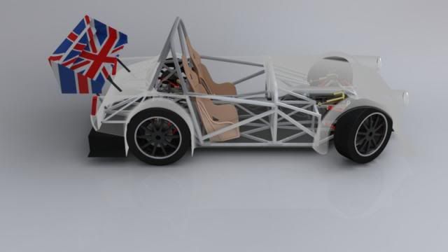
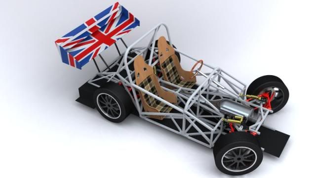
I'm attaching some pictures of the most current frame/car I've designed. There are more pictures/link to even more pictures in my Garage of my midget.

Ignore the goofy British flag rear wing. I am by no means claiming this chassis is perfect. Some load paths are compromised to make for easier fabrication and I never conducted an FEA on this chassis I only went off experience learned from the other 3 chassis that did go through FEA. Finished with all tabs/brackets and a Full SCCA legal roll cage for a 2500lb car it weighed ~280lbs. You can see however that the entire chassis layout is around putting tubes where the suspension/drivetrain/roll cage wants them. The largest tube is 1" square with some 3/4 & 1/2" square mixed in. I would change a few things if I did it again but after building it I'm fairly happy with how the design turned out.
 photo carfinal2_zps0f6dc903.jpg

 photo 04-04-09-03_zps3c8aba75.jpg

 photo carfinal4_zps59e69882.jpg

This car was built around the running gear (Brakes/uprights) from a 4 lug 2nd gen RX-7 with a Miata Torsen Diff. Track width is OEM 2nd Gen RX-7. I used the MG midget steering rack unmodified. Front uprights retain the stock upright/hub with a fabricated adapter piece for the Strut to dual a-arm conversion that includes the new steering link.

Even utilizing this level of OEM componentry I still followed the plan I laid out. I think re-using a stock component without still designing around it's dimensions is a cop-out. The idea of slamming Miata subframes under cars because the Miata works good is short sighted. There is still lots of work that must be done to ensure good performance. Spring rates, Roll axis to CG rates have to be matched up to ARB sizes, Ackerman has to be corrected etc. etc. I left Anti-squat/Dive out of my analysis because I've found it unnecessary in my experience. Generally speaking the car's I've been playing with have CG heights very near to the 1/2 wheel diameter.

It sounds like you've made some decisions so I would focus on finalizing the suspension design prior to working on the chassis. I'm assuimg you've picked a wheelbase if you have a estimate of Weight distribution?

Giant Purple Snorklewacker
Giant Purple Snorklewacker MegaDork
10/1/13 5:06 p.m.

In reply to nocones:

What is that drawn in?

nocones
nocones SuperDork
10/1/13 5:08 p.m.

Awesomeness.

Pro/E wildfire. Renderings were completed with hypershot. The best part is its fully assembled using mechanica. Everything actually works. The tires move the pushrods that move the belcranks compressing the shocks. Grab the steering rack and it turns the wheels showing Ackerman and camber change due to caster. I can adjust camber/caster/toe in the model.

I should really get paid for this car design thing.

NOHOME
NOHOME Dork
10/1/13 7:38 p.m.
nocones wrote: I think re-using a stock component without still designing around it's dimensions is a cop-out. The idea of slamming Miata subframes under cars because the Miata works good is short sighted. There is still lots of work that must be done to ensure good performance. Spring rates, Roll axis to CG rates have to be matched up to ARB sizes, Ackerman has to be corrected etc. etc. I left Anti-squat/Dive out of my analysis because I've found it unnecessary in my experience.

As someone who is contemplating just such a project for the same resons you state, I have to fully agree with you.

However, for those that are not fully aware of the compromises that are involved in using a Miata suspension as a starting point, let me suggest that by doing so they are still going to end up light years ahead of trying to do their own suspension from scratch. It may not be perfect for the application, but a lot of good enigneering is going to end up in place. It's a relatively safe place to start learning from.

mblommel
mblommel Reader
10/1/13 8:45 p.m.
dragoon119 wrote: In reply to mblommel: Where? Below the engine compartment, tunnel, firewall, and rear roll bar? Is that where triangulation is needed more?

Basically if you have a square/rectangular opening in you frame it can flex. Squares are not rigid, triangles are. If you take an open rectangular section and connect the two opposite points with a member you form two rigid triangles with very little weight gain. Hence the term triangulation. The important forces being applied to the chassis will come mostly though your suspension pick up points (I'm assuming you're not going to using big aero elements) so I would focus on making those points rigid or at least designing in how much movement is acceptable.

Once again my FSAE experience says get the components you're planning to use, establish your wheelbase, pickup up points, track width, etc. THEN connect the dots with the frame. I think you're starting at the wrong end of the project. Remember the frame's only purpose is to locate stuff and do it with some amount of desired or designed rigidity. It's lots of fun to draw up stuff in Solidworks, but you're wasting your time if you don't think the process through before firing up the CAD software.

Our team's suspension guy chugged through Milliken and Milliken to establish our design. I'd start there. You can also pick up a lot of good info over at the FSAE forum, but I would keep a low profile with your current state of knowledge. There are some super sharp kids over there that are pretty merciless to those who ask questions without doing extensive homework first.

Good luck!

dragoon119
dragoon119 New Reader
10/2/13 11:23 a.m.

In reply to Adrian_Thompson:

Fear not, I have not been frighten off!

I have recently posted the information on the theoretical specifications of my car and believe that the suspension is the only thing left to do at this point. Well that and the rendered drawings, but I'm hiring someone for that as I'm only good at 2D side view car drawings.

Either today or tomorrow when work is not in the way I should have a theoretical front suspension mock up in the Cad software for everyone to critique.

dragoon119
dragoon119 New Reader
10/2/13 11:43 a.m.

In reply to mblommel:

About 4 posts above this one I've listed the specs on my sports car. At this point the only things hanging in the air are the:

Wheel knuckles I'm about to use. Brakes Steering rack Shocks/ mounting location

I am going to try and address the wheel knuckles first, the brakes should be determined with the 16 inch wheels of choose since I am not putting the brakes inboard. I would like the steering rack to be out of a Corvette Z51.

Well thats all I got for now.

dragoon119
dragoon119 New Reader
10/6/13 6:03 p.m.

In reply to Adrian_Thompson:

I told you I wasn't frightened away! I'm back!

In reply to Giant Purple Snorklerwacker:

I'm gonna have a smaller model made of plastic to test forces on in a couple of weeks! Gonna try that out.

In reply to Nocones:

I'm recently downloaded Lisa so I might finally understand what everyone means by FEA. I can hear you facepalming right now! Anyhow, After, doing some models on the engine and such, I've decided to go with a pull-rod suspension set up in the front and a unique push rod set up in the rear. I understand that pull-rod set ups have a problem with anti-squat... Anyhow, the weight distribution I want is 48/52 but I will lean as far as 45/55 if need be. I really don't want to go 40/60 as the thought of accelerating forces puling the frontal weight into the thirties is just frightening to imagine.

In reply to mblommel:

Thanks to you I triangulated the living crap out of this model. Really, everywhere I went all I could think of was triangles, at work, at home, in my food. I hate triangles now, I want a circule or a square, anything but another bloody triangle! Okay, rant over. Thanks for the site, I'm gonna be ghosting their for months so beware... I'm watching.

On that note, I would of uploaded updates sooner but I was holding off until anyone could give me the measurements on an AY-6 tranny. With those in hand I finished the model. So guys, I'm ready for round 3!

Leafy
Leafy New Reader
10/6/13 6:07 p.m.

I seriously think this model is too far gone at this point. Now that you know where your suspension points are going to be, delete everything besides those points and then connect the dots. You still have a bunch of tubes that arent doing anything, a bunch of points where you need bracing and a ton of tubes that are way too big. Starting over completely from scratch I bet you could make it way stiffer and 30-50 pounds lighter, that looks like a 120+ pound frame.

jstein77
jstein77 SuperDork
10/6/13 7:56 p.m.

Start by copying everything Factory Five does.

Keith Tanner
Keith Tanner MegaDork
10/6/13 8:06 p.m.

Or read the Exocet reveal thread. It's full of good discussions of how the frame was designed and why and very well illustrated.

Using existing suspension components is a good option if you're mostly interested in frame design, as it lets you skip some pretty difficult stuff. Taming roll center movement, bump steer and camber curves is a big project, and if you try to design absolutely everything you're liable to build nothing.

Ian F
Ian F UltimaDork
10/6/13 8:46 p.m.

In reply to Keith Tanner:

Pay attention to what Keith and others have been posting. Learn to walk before running... or maybe learn to crawl... since if we're being brutally honest, you're not out of the crib yet.

From the looks of your pictures, you've basically ignored most of what they've been advising. These are guys who have actually designed and/or built frames for cars that have track time (and haven't fallen apart). Pay attention to what they say. If they say start over with a clean sheet, it may be advice worth listening to. I know you've put a lot of effort into what you've done so far, but sometimes you just have to treat it as a learning experience and go back to "GO".

1 2 3

You'll need to log in to post.

Our Preferred Partners
m7mQtqjOr893fOCSaFJIqk4aU3KDGaFmgn5ERZbtCUtySKVsGv8i0BzpZaCF3EzE