I would think that a vacuum chamber that goes to all four would make it worse, not better.
Not having done it yet with such short runners, I wonder if the best chance of success would be tapping into a single runner and using timed sampling.
Alpha-N always struck me as fiddly because of the way it appears the math that Megasquirt uses, which is why I always shied away from it. That and I have never had a TPS that was repeatable position-wise. (Cheap parts) I do want to try it, but it looks like you have to map every grid square instead of working by extrapolation.
How about MAF? MSExtra has the code to support a MAF sensor of course...and from a practical standpoint I do need to make an airbox...if I can find a way to do it with an air horn setup like this:
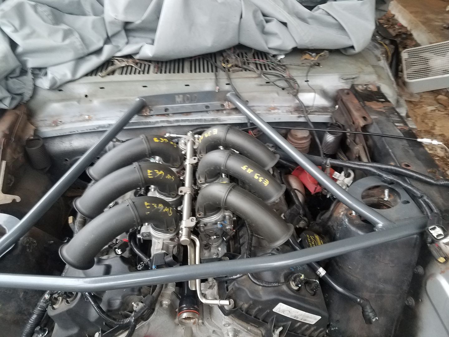
The airbox is of course required anyway because of the "shooting-yourself-in-the-foot" nature of individual filters when it comes to ITBs(shared filters aren't possible with this setup that I can see)...it would give me a chance to integrate a MAF sensor(which will also make the Ti-VCT much much easier to tune).
P.S. I have probably 8-10" between the throttle plates and the valves.
In reply to Wicked93gs :
MAF is always preferable, IMO, but alpha-N should have throttle response benefits at low RPM.
@SkinnyG, I have used the 2 wire Bosch (available on my BMW and VAG cars in the early/mid 90s) with very good luck. They are simple PWM control around 100hz, and the circuit requirements are very, very simple.
@Knurled - if you have a bad TPS signal you will want to kill yourself on AlphaN, heck even a dedicated ITB mode as it's critical. Pure Speed-Density you can deal with it as you can increase the filtering on the tps or use a volts/sec cutoff to get rid of any issues, when it's only used for accel/decel it's much simpler.
Thread hijack - If I had a turbo + ITB setup running on MS2/MS3, would Blended Mode be the only sane option? Also I assume the vacuum reservoir (and all lines) would need to withstand boost pressure, or possibly have a check valve?

Didn't someone make a 4 MAP sensor arrangement with an electronic "combiner" for a single output?
Also a MAP system would need to be separate from a IAC system, as the IAC would confuse the MAP.
Another way for IAC on an ITB might be a Stepper on the throttle stop (geared cam or wedge).
There is however an inherent design flaw in injected ITB implementation. An ITB violates a few of the principals of intake tract design. One is that you should gradually accelerate the air to the back of the valve. The other violation is that you should not change the acceleration of that column of air as it traverses the port tract. Most ITBs are straight not tapered, and the throttle shaft and blade bisecting the port creates as much as a 20% loss in airflow thus a good percentage of the ram effect energy is lost at the throttle shaft instead of contributing to VE.
This can be countered by using a rotary valve or a Slide type air valve, this has the advantage of reducing the airflow inrush issues found with multiple blade type air valves. This makes it easier to modulate power in low traction conditions.
A long tapered port runner into a plenum and the throttle valve on the plenum fixes both of these issues and simplifies throttle control, Idle, and cylinder balancing, all at once.
In reply to Paul_VR6 :
Technically you do not need a TPS at all for speed density. A lot of PNP setups don't use one, relying entirely on MAP based enrichment. My RX-7 in its first incarnation just had little plunger thing that maxed out over 1/3rd throttle. At which point enrichment was no longer necessary, which is probably why Mazda did it that way in the first place.

In reply to bentwrench :
A well designed ITB system does indeed accelerate air gradually to the back of the intake valve...once the throttle plate is open at least...most air horns you see have a taper built in, being slightly wider at the bell mouth that the side that connects to the throttle body....as for most ITBs not being tapered...I would have to disagree with you there...most are in fact tapered to some degree or another(though you can indeed buy cheap aftermarket ones that are not). The ones I am using are from a BMW M3 v8....and the size at the throttle plate is 50mm....which then tapers and changes shape to an oval shape where it bolts to the head...in this case, both the Ford and the BMW port shapes are almost identical, with the Ford being just a bit larger in the "corners":

You can see what I mean from the CAD file I made for the adapter plates. Normally 50mm ITBs would be too large for any sane streetable engine...but again, the Ford engine shares a feature with the BMW engine here...long relatively small intake ports....so(in theory at least) the performance of these ITBs should be identical to how they perform on the M3(or close enough to make no noticeable difference). Effectively by the time the ITB gets to the port size the size is much closer to 37mm...averaging out at 43.5mm...small enough to keep velocity up to a reasonable degree. As for the airflow loss at the throttle shaft...not a whole lot to be done there...but even a 20% loss of 43.5mm results in an effective size of 208mm worth of airflow over 6 cylinders...FAR more than any single throttle plate could reasonably hope to flow(also far more than the engine could hope to use at WOT in a NA configuration, but that is another matter). The biggest flaw in my design here is that the Ford intake ports are slightly larger than the BMW side at the flange...and that DOES violate the rule that ports should never get bigger as they aproach the valves. I am just hoping the difference is small enough as to make no practical difference. I did of course hand port that area to smooth the transition.
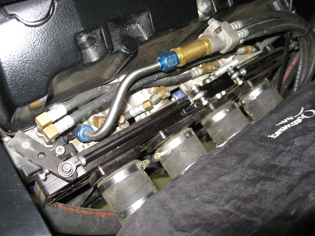
Slide ITB on a Honda
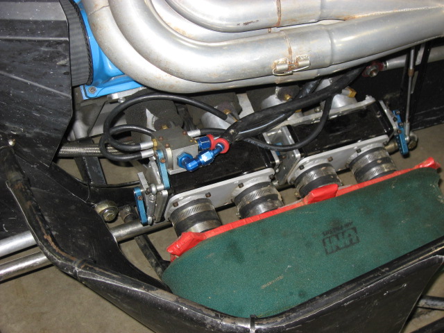
Rotary valve ITB on a Ford
These are both motors making on the plus side of 2HP per cubic inch
In reply to maschinenbau :
in a turbo application, an airbox is of course a must....and if using an airbox you can run a MAF sensor...assuming that the turbo isnt oversized for the engine(meaning the engine is often in boost), the most important part of your VE map is going to be above 100KPA anyway, your resolution below that is going to be marginal and only really relevant for cruise and idle conditions in any case...assuming you had a decent MAP signal you could probably get away with Speed Density even if you dont use MAF
In reply to bentwrench :
I seem to remember reading in Maximum Boost Corky Bell saying that slide valves just weren't a viable option for street engines(Not that he is the end all and be all of performance engines, but that is a pretty good book) but I dont think I have ever seen either a slide valve or rotary valve anyway...I need to look into it.
In reply to Wicked93gs :
The slide valve is very good but will not work with closely spaced intake ports.
We designed the roller valve mainly to use on motors with a Chevy V8 port spacing.
In reply to bentwrench :
Is a roller valve like those air conditioning port ball valves essentially on some type of axle? Just tyring to imagine it.
It's actually 2 rollers, we worked on the design for 2 years and got a patent even.
Very simple, picture 2 rollers with a half moon cut out of each, the rollers are synchronized.
We named it CenterFlow as it opens like an iris but is not round until fully open when it presents a completely smooth bore.
It is very slow opening and we had to do trickery with arm angles on the linkage to speed up opening on high traction surfaces or for drivers who could not adjust.
Alan Johnson visited us looking to see if it was good for Top Fuel but the slow opening is a problem for that application.
It really shines on a Sprint Car motor with a dry slick track, the slow opening makes it easy to keep the tires under you. It would be outstanding in the rain as well.

I wanted people's thoughts on the factory BMW ITB vacuum manifold(circling back around to the topic at hand):
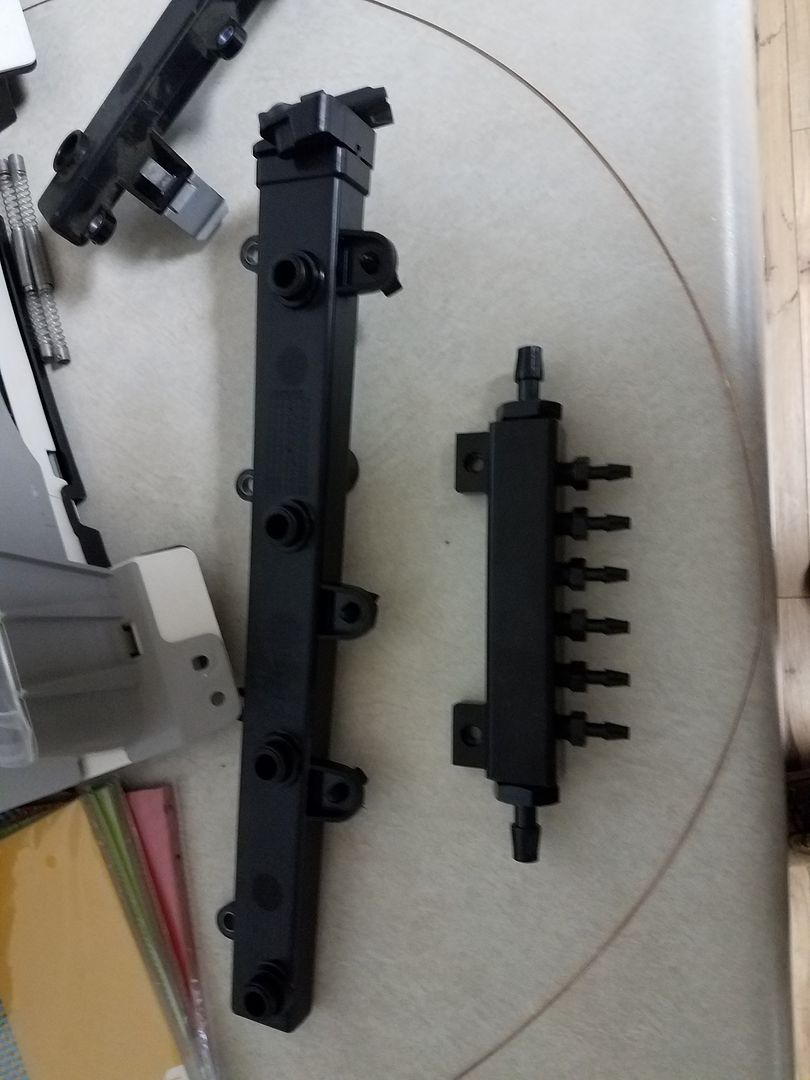
Ignore the vacuum block here...just something I bought before I settled on the catch can being a better manifold option. Now, BMW has been building factory ITB cars for decades so I figure their engineers know a little about them, This is the factory M3 manifold....a couple things of note here....the MAP sensor at the end, indicating BMW pulls a fairly clean signal with this design(otherwise why bother?) The 2nd thing is the taper itself...just like an intake manifold...what do you guys think the purpose is with the taper?(maybe there is a certain minimum volume needed?) Thirdly notice the little pipe connectors where this thing presses into the throttle body and seals with an o-ring(on both sides oddly) and the whole thing bolts to the TBs...I suspect that the reason BMW uses a manifold for each bank is something I read on Kinsler Injection's website...they were discussing supplying fuel to the injectors on single throttle bodies and they said that you should always use a fuel rail if possible because individual hoses from a distribution block are more susceptible to pulses from the injector opening and closing. The same principal "should" apply to air entering the valves...as they open and close there will be a pulse(air is just a thinner liquid after all)...so if you use in this case a "vacuum rail"(instead of a fuel rail) it should minimize the pulse. I simply don't have the space available to create any such vacuum rail with my ports being as close to the valve covers as they are, but I thought it might be worth considering for other people trying to get a clean vacuum signal.
@ knurled, yes possible but as the throttle body area to displacement increases it gets harder and harder. My favorite example of how fiddly map only enrichment is putting anything but an exact 1m vacuum hose into a g60 corrado.
In reply to Wicked93gs :
Seems like they are also using that for a balance tube, due to the diameter of the passage for each cylinder.
The taper is probably to help even out the way the pulses from each cylinder hit the MAP.
Probably drive by wire so no IAC needed.
In reply to bentwrench :
It was drive by wire....but it did also have an IAC that sat between the banks and connected the back side of each manifold with a larger 3/4"-ish hose
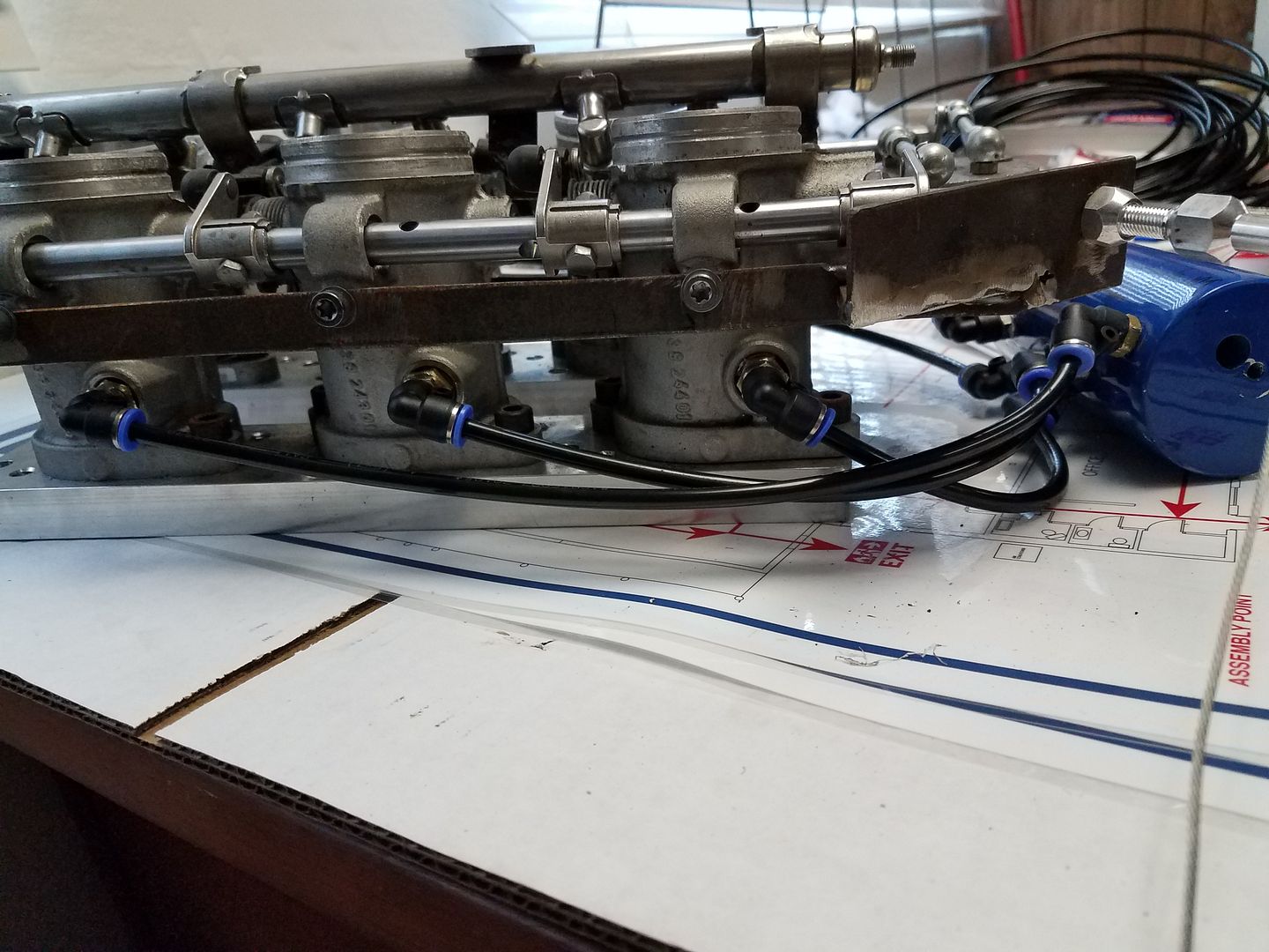
The vacuum tank system coming together
Bit of an older thread, but I'm curious if and how this ended up coming together?
And those vacuum hoses and fittings in the pic above, are those the push to fit type of stuff that you can find in the plumbing area of the hardware store, or something more unique?
One option for getting a good vacuum reading is to solve the problem electronically rather than pneumatically, mke did this with his FrankenFerrari to run the ITB'd V12 using a multiMAP board that has a bank of per-cylinder sensors and outputs the highest vacuum reading among any sensor at any time, IIRC he designed this board himself and uploaded it somewhere:
https://grassrootsmotorsports.com/forum/build-projects-and-project-cars/frankenferrari-v12-ferrari-308/148959/page58/
On a piston engine with ITBs, I would not bother trying to run speed-density.
One option if you are stubborn would be to run the MAP off of only one cylinder, and used a timed MAP sample. I know MS can do this but I have no experience with it to know how well it works.
The best solution I'd ever seen was on a 16v Scirocco. The throttle bodies drew air from a common plenum that was connected to an airflow meter. (The airflow plate in a K-Jetronic counts as an airflow meter)
Part of me wonders if you could run a MAP on a venturi to get an airflow signal that way. But at that point it seems easier to eliminate the injection altogether and use an arrangement of calibrated orifices to meter the fuel directly, maybe with an air bleed and a mixing chamber to emulsify the fuel, kind of an "emulsion well" if you will...


My new solution for this: I used an electronics enclosure and plan to run hardlines to each ITB. I wanted to be able to fit check vlaves inside. I have read reports that if you run (number of cylinders)-1 check valves you can get a relatively strong 15+ inches of vacuum and a stable signal. I thought it was at least worth a try...at the very least it gives me a lot more volume than the log I was running before.
this is a really interesting thread pushing the boundaries of my knowledge and understanding. I know we tried to run Alpha N on my ITB rotary but couldn't get it to run right and gave up, however I have miles of running length but when I shorten it, it may be worth a revisit as I have a simple block style manifold like you show for your early prototype.
are you putting a chopped up BMW intake manifold on a ford v6 swap and running MS3???
I think the check valve box may work well with brakes but maybe not for MAP. Have to think about it a little more.


