
Stampie
UltimaDork
9/20/19 8:32 a.m.
AngryCorvair said:
Bumping because cooling concept has changed. Mounting radiator in the former engine compartment, with the OE fans in their OE puller configuration. I can make whatever inlet and outlet ducting I need. The lower valance has 2 vent areas, each is 15” wide x 2” tall, for a total 60 sq.in as seen below:
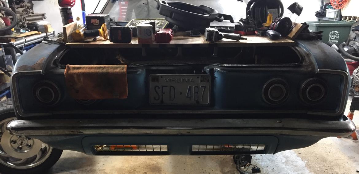
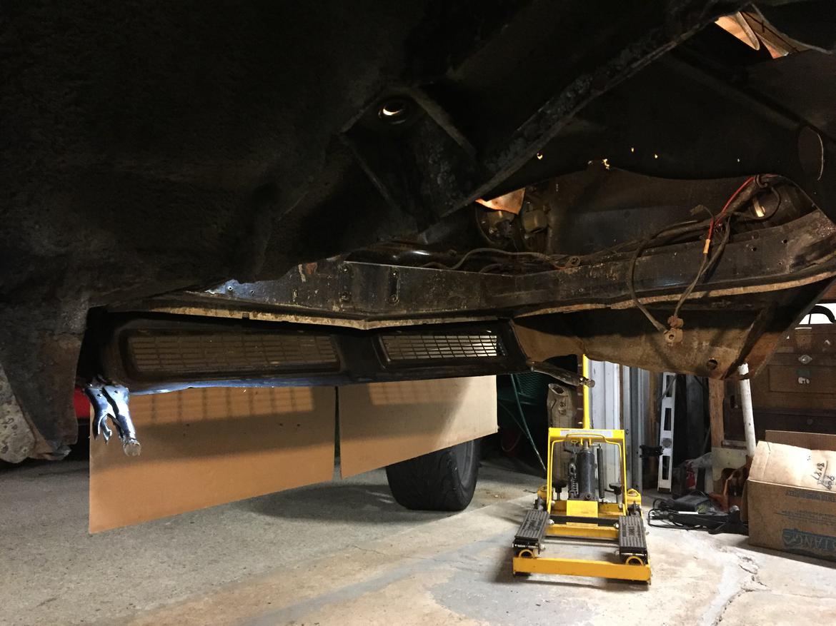
I’m OK with enlarging those vents, probably by making an entirely new panel from stretch-metal. Total panel area is 40” x 6” = 240 sq.in. I’m also marginally OK with venting the decklid. This could be a temporary setup to get through the Challenge, or if it works well it could be permanent.
Feedback please!
For the Challenge a leaf blower in the staging lanes worked for us.
It looks like the lower valence (with the vents) is a removable part. Do that ti get more open area and less restriction. Add baffles to make sure the hot air gets out of the engine bay. For short runs, limited cooling will be OK, but may require dedicated cool downs between runs. Those could result in fewer runs and/or reduced consistency in the runs.
Generally the two worst cases for cooling are: full power extended runs at speed (most power input to the cooling system) and post-run traffic (sitting after high power application). If you can come up with the baffling to get cool air to the core and a dedicated duct to get the hot air out then you have done all you can without getting to cutting body panels. Venting the decklid would need to be part of the system so that the flow does not get bypassed at one condition or the other (at-speed/sitting).

Robbie
UltimaDork
9/20/19 11:14 a.m.
Think about air in, and air out (I know you will but remember to consider both - its common to optimize one but forget about the other).
Also, think about pressure differentials. Air moves based on them. even with good sizes and good ducting, if the pressure is the same on both sides of an exchanger, no air will flow through. At the back of the car, high pressure zones are harder to find and harder to predict.
So my clearly scientific answer is: make large in and out ducts and run the fans for pressure. Sorry that's not more helpful.

Kramer
Dork
11/17/19 4:19 p.m.
Use a factory fan blade on a solid mount and make duct work to direct the airflow over the hot bits. Hey, it worked for all those corvairs.
I’ve got a couple ideas I’ll probably try:
1. Being a 60’s GM product, it’s got those awesome kick panel vents that are fed by high-pressure area at base of windshield. Thinking about dryer duct from passenger kick panel to engine bay.
2. Similar concept, but using empty inner headlight bucket as source.
3. Still have option to put radiator in frunk

reviving my own zombie thread for a slightly different question:
i want to build a duct down the center of the car, from the base of the windshield to the front of the engine. this will provide combustion air as well as some blow-through cooling air. total length will be about 8 feet, and the cross-section will be about 36 sq. in.
a little bit of math says my 5.7L engine at 6000 rpm will need 1215 cfm, and (assuming 50% of duct area feeds engine) in a duct of 18 sq in, the air speed will be about 3688 in/sec = 324 ft/sec = 220 mi/h.
is that an unreasonable airflow for a 3"x 6" duct about 8 ft long?
i think it's probably OK considering the following:
the throttle body is 2x 48 mm, so throttle area is 5.6 sq in, so i'm feeding it with a duct that's more than 3x throttle area
OE inlet duct is about 2 ft long and about 3-1/2" diameter (9.6 sq in) at the filter box. it chokes down to an oval cross-section about 6" wide and less than 2" tall where it goes over the top of the radiator.
time spent at 6000 rpm should be really brief. and hopefully not catastrophic. also, when the car is moving forward there will be some amount of positive pressure feeding the duct.

I answered about header bags in your main build thread.
On the center duct from the front of the car to the intake/radiator/engine bay, you don't need to make the intake duct the full length. It could split off from the main duct at some mid point that you have access to, for filtration etc. I would be concerned about getting enough mass flow to the radiator and then having anything that resembles a small breeze for the rest of the engine bay cooling. 36 sqin of total area over ~8ft MAY be enough to handle the cooling at continuous speed, but the on-off nature of a competition car along with the low speed nature of autocross will tax the system pretty quickly. Dedicate the entire 36sqin to rad cooling if you can. The cooling fans you are planning to use will do a good job of passing the air, but the old rule of drag increasing with the square of speed will be compounded by the effective reduction in cross section from boundary layer growth. Area changes can help alleviate some of that by tripping the boundary layer and setting it into a different flow regime, by the length is going to make small cross-sections worse. I did see at least one suggestion to pull some cooling air from under the car and that will be a great addition to the central intake. It would allow the engine to get as much air as needed and the make-up air could come from underneath. A mixed approach is likely going to be the cleanest option. Watch out for road debris damaging the radiator face...
My abuse test for cooling systems with a "boutique" auto manufacturer was: A figure-eight with centers at about 300ft apart and a 20-30ft radius on the ends. This simulated an endless series of rolling 2nd gear pulls to near red-line. If a car made it through more than about 20 laps without puking the cooling system or showing other signs of overheating, I deemed it acceptable for the power/cooling levels and the antics the customers would likely put the car through. Basically it was minimum 20 rolling stop light drag races, with little to no cool down time. We had access to a decommissioned runway and we made use of it.
In reply to stafford1500 :
Thanks for the detailed replies! sorry, I didn't paint a clear picture with my description. Attempt #2:
I have gone with front-mount radiator, bottom-fed via dam/scoop under front valance, with cooling air exiting behind front wheels.
the central duct is only for combustion air and flow-through cooling of the engine bay. It will be fed from high pressure area at base of windshield, and exit through vent at base of backlight plus louvered rear decklid.
I have the space to increase cross-section of this duct to 7"x7".
duct length, from base of windshield to throttle body, is [edit] 96".
More info on primary cooling system:
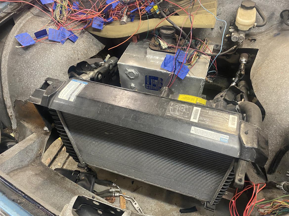
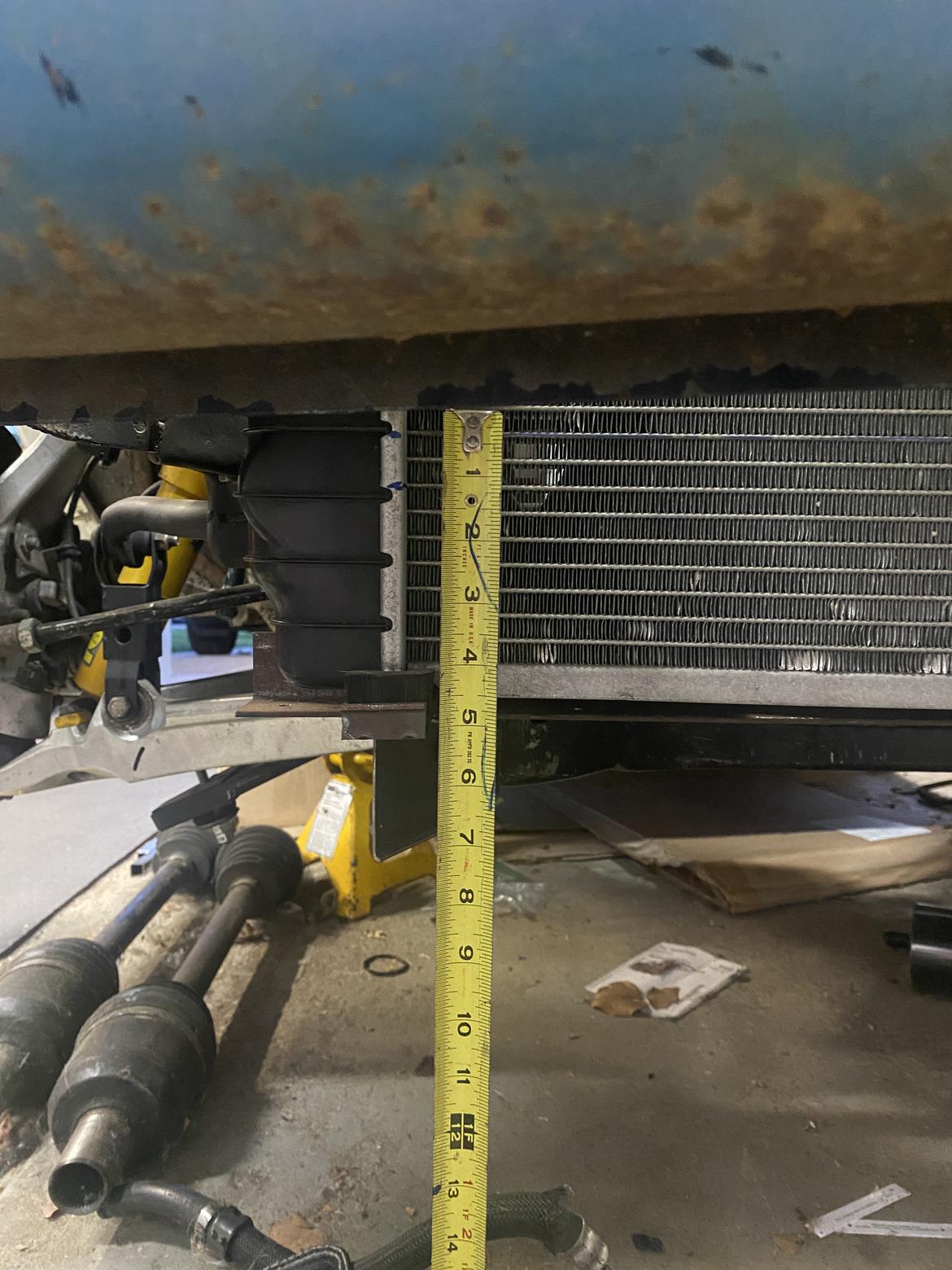
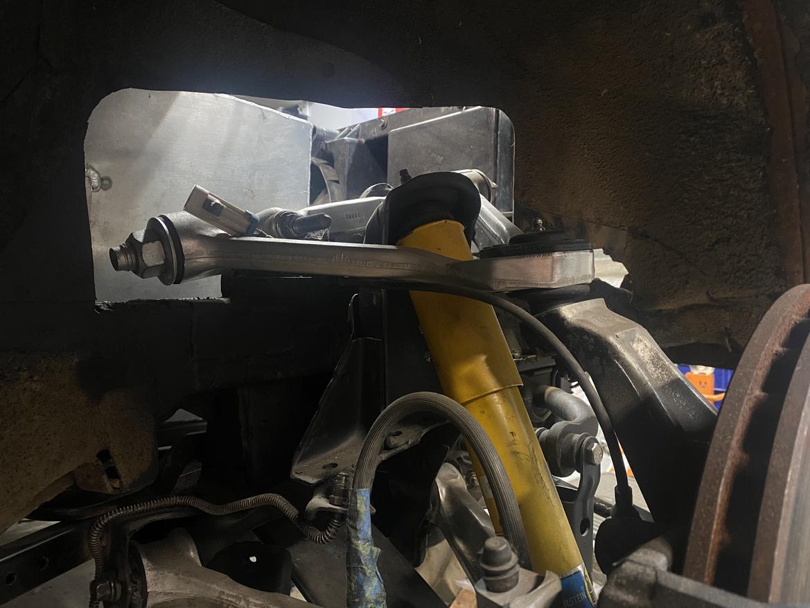
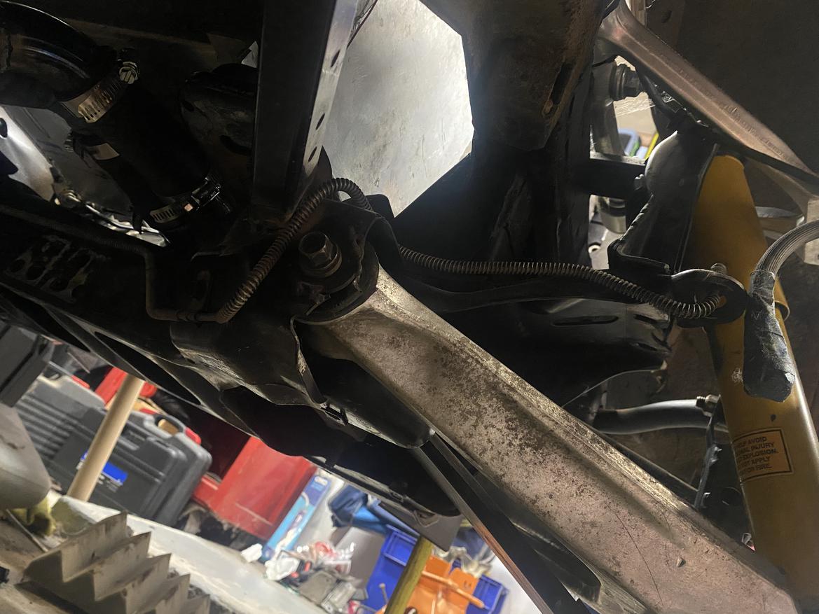
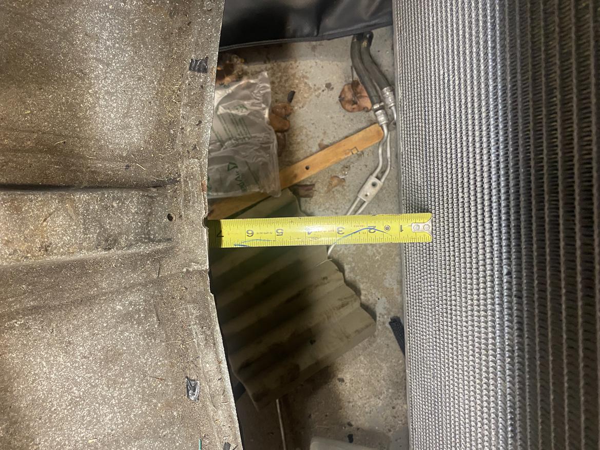
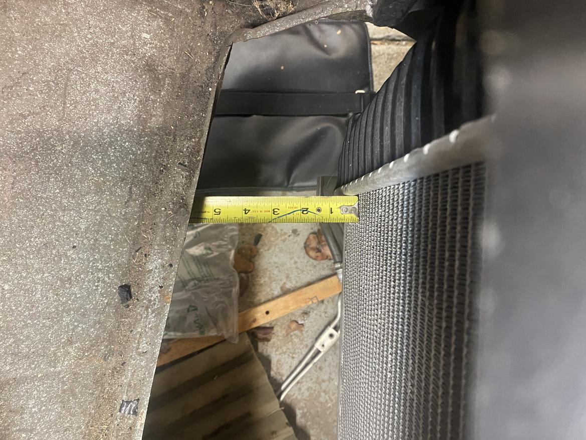
radiator is stock C4, aluminum and plastic, 2-row with core 23" wide by 17" tall. Bottom 4" of core are in direct airflow below front valance. Radiator is bottom-fed through a full-width opening that is 7" wide in the center and tapers to 5" wide at both ends. Air dam / inlet scoop and duct from front bodywork to rad core not shown. Stock C4 puller fans. Air can escape frunk above/around both UCAs as well as down past the unibody rails to under-car. Pix for clarity:
With that clarification I think your cooling will be good.
The intake /engine bay cooling duct should work pretty well with the dimensions you gave earlier. The distance on ducts like that add up fast dont they...
In case stafford1500 looks at the Aero forum, here's a couple of inside views of engine box venting to base of rear window:
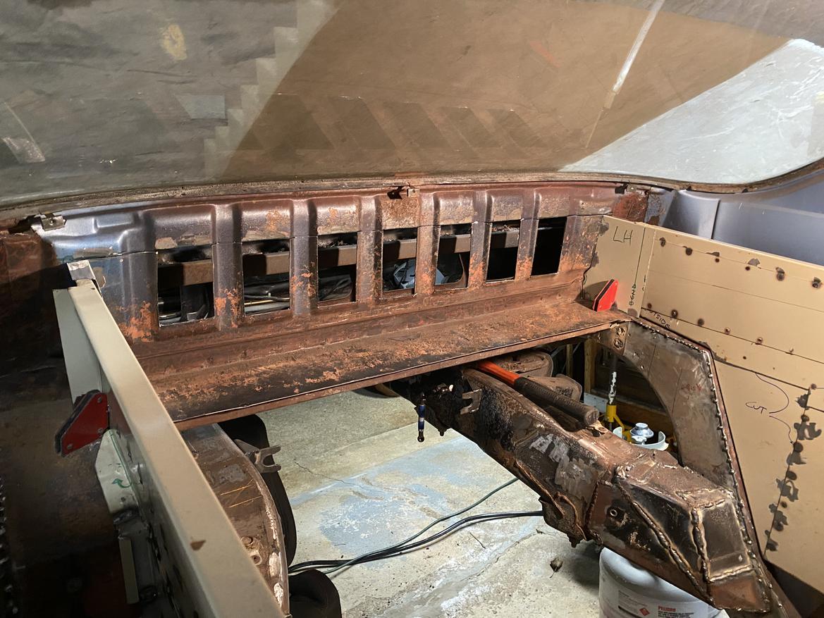
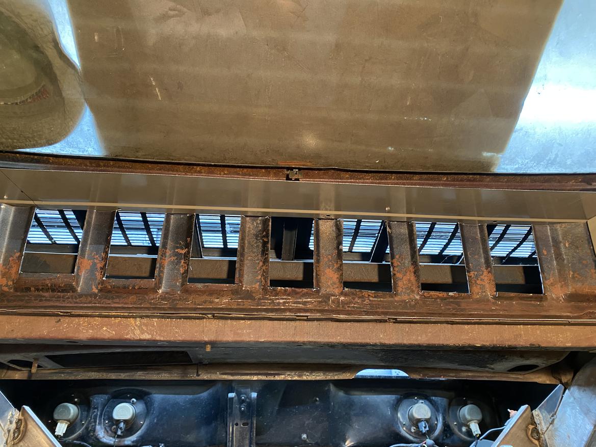
And here's a couple of outside views:
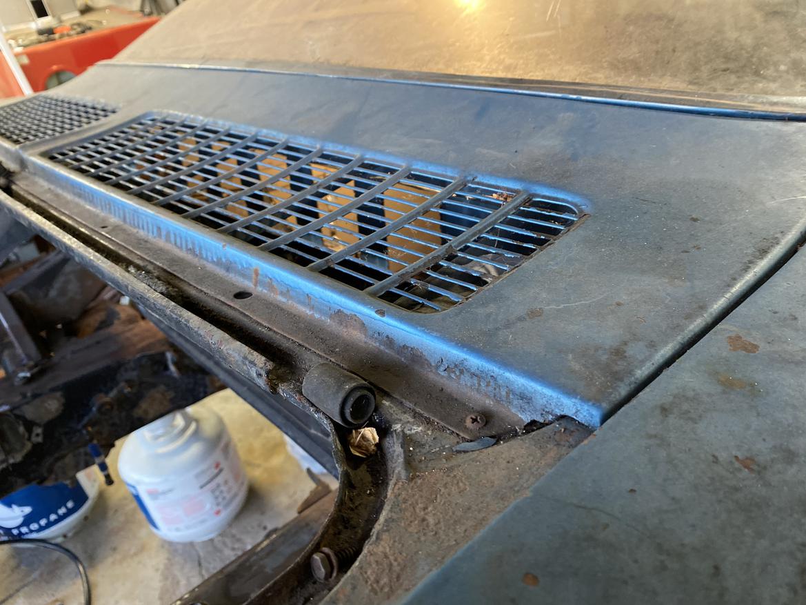
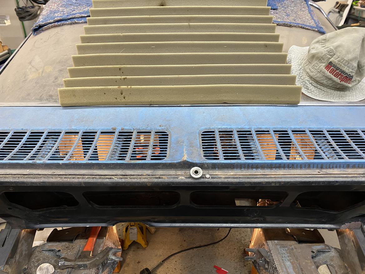
Feedback?
In reply to AngryCorvair (Forum Supporter) :
That piece of foam says that you should put some old-school sexy louvers over the rear window.

In reply to AAZCD-Jon (Forum Supporter) :
Believe me, I saw it too. But that's not the type of feedback I was looking for. :-D
In reply to AngryCorvair (Forum Supporter) :
I saw your post in the build thread earlier. Just getting to a point where I can take a breath today. I think you will be all good. The overall slope from the front to the back will be most useful for post-run cool down. You may want to put some temp stickers on the cover in a few spots to catch max values and decide if/where you may need more insulation post-challenge.
A leaf blower applied to the duct inlet at the front may give you some idea of overall flow diffusion/restriction.
stafford1500 said:
In reply to AngryCorvair (Forum Supporter) :
The overall slope from the front to the back will be most useful for post-run cool down.
it's only about 1" rise over 36" run currently, which will give me a good baseline. if necessary, i could achieve about 2", maybe 3", but not gonna tackle that until i see where it falls on the post-Challenge "OMG stuff to fixxor" list
You may want to put some temp stickers on the cover in a few spots to catch max values and decide if/where you may need more insulation post-challenge.
that is a great idea!
A leaf blower applied to the duct inlet at the front may give you some idea of overall flow diffusion/restriction.
that is another great idea! i appreciate the feedback.
Your engine will not draw 1215cfm unless it is making about 1800 horsepower 
300hp rally cars make that power through a 32mm restrictor that cuts the power when air reaches .5 Mach. It takes more power to move the air through faster than that than the engine can get from that air. (That sentence needs to be drug out and shot) Extrapolate that to about .3 Mach that you calculated for 18 square inches.
Look at the size of your throttle blades, your air cleaner duct, that is a more appropriate approximation of how much air the engine will need.
We use several of these to monitor insulated concrete forms and pours during the winter. Phone app with continuous time recordings.
SensorPush.com: HT1 Temperature and Humidity Smart Sensor $49.99

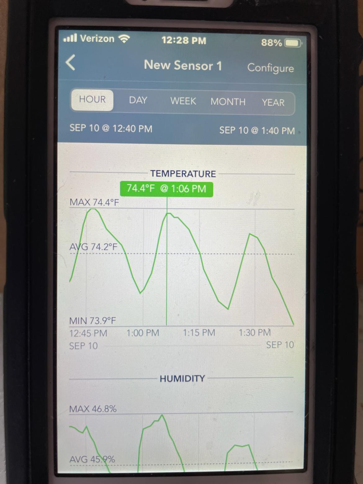
This last photo shows the real time data log you can achieve.
Waking the semi-dead to ask stafford1500 if this is the stuff:
https://www.amazon.com/Ceramic-Blanket-Density-Furnaces-Insulation/dp/B07NJKS38T/ref=mp_s_a_1_6?crid=28V3L42O1KIZH&keywords=kiln+insulation+1%2F2%22&qid=1685472893&rnid=2470954011&sprefix=kiln+insulation+1%2F2+%2Caps%2C185&sr=8-6
I was thinking about cutting it into strips and wrapping the headers with it. Any knowledge of whether or not this would (1) survive and (2) keep header heat contained? Or is this supposed to line the heat shields and engine bay panels? Or somother application I'm missing?
Here is the McMaster link to the stuff we talked about.
https://www.mcmaster.com/catalog/129/4002/93315K71
I would not apply it directly to the primaries, since it will have the same effect as header wrap, which is holding moisture to the steel when it cools off. My application is as the wool/glass//steel stuffing in a glass pack muffler, but a layer pinned to the inside of your header bags/heat shield will go a long way to keeping heat where you want it.
Make sure to try the propane torch while holding a piece of it to prove it to yourself (after you heat it while not in your hand first).
Your linked item looks very similar at first glance
In reply to stafford1500 :
Thanks for the additional info, I'm gonna give this stuff a try.


