In reply to Lof8 - Andy :
I've got these 1 1/4" aluminum couplers from Amazon at the joints under the clamps. You use a heat gun just like an electric heat shrink tube, it's just a thicker more substantial material. Super easy to install.


In reply to Lof8 - Andy :
I've got these 1 1/4" aluminum couplers from Amazon at the joints under the clamps. You use a heat gun just like an electric heat shrink tube, it's just a thicker more substantial material. Super easy to install.

Dang I like those hose clamps! I feel your pain with dash wiring ... was out in the garage fooling with it all day in the Europa today ....
I didn't get much of anything done yesterday. I ordered all new Koni Yellows only to realize I ordered the wrong fronts. Due to the type of 911 strut housing I HAVE to order a specific 911 part number so they will fit the housing. I sent those back in and yesterday received the proper replacements. Unfortunately I noticed some oily substance covering the inside of the shipping box and upon opening one of the packages found this.

One of the front struts made it out fine so I will be waiting a little longer for the replacement to come in.
For the rears I have been waiting on my $27 coil spring adjuster kit to come in.

I chose this set due to price but also aluminum top hat. It would need drilled to match the OD of the Koni shaft.

Luckily the sleeves fit the Koni body perfectly, so no worrying about them being larger than the clip they rest on. The sleeve is upside down in the pic as I wasn't sure if I needed adjustment at the low range or high. Based on pics of others setup it will be higher.


When I got home I was digging through some parts looking for a specific diameter coolant hose and found some old KW top hats from the FRS. They fit the Koni shaft perfectly and also have a better stack height. I ordered up a couple spacers to take up the distance to the nut. All I lack now is 8" long ~140lb springs, rear bump stops, and new top bushings.


Wow, what happened to that shock that it came apart like that?
You're only running 140# springs in the rear? I'm running 400#, about 9" long, in the back of my Mini hot rod build. I think mine are going to be too stiff - I think I'll wind up somewhere in the 250 range but they claim that's what I want. We'll see......who are you getting your springs from?
Are those black adjustable spacers plastic or aluminium?
In reply to MiniDave :
It almost looked like the crimps that hold the body to the cartridge weren't done properly? I really don't know what happened, especially since the box it came in wasn't remotely damaged at all. There was oil everywhere and since it's my workplace countertop for incoming customers I couldn't really dig into it much further.
From my research the 140lb is a good street coil, maybe a bit soft for autocross or track work. I've decided to try the softer first as I probably will be adding in a rear sway bar. I really would like a compliant setup if possible.
The adjusters are aluminum. There's dozens of versions of these on ebay for ~28-45$ shipped. Some have a poly top hat, so keep that in mind if you ever order any. The springs are always absurdly high rates in all of the ones I've bought.
I haven't decided on where I'll get them but it appears that Eibach has the length, pounds, and diameter needed. I haven't checked Hyperco yet, and I'm curious if I can use longer springs than 8". I have seen most use helper springs with the 8" but don't know if I would run into coil bind with longer springs.

I'm stoked that you used those heat shrink hose clamps and couplers. I have been curious about them. Am I remembering correctly that they have a special cutter tool as well for removing them without hose damage? Build looks rad!
In reply to GoLucky :
I haven't looked into removal but some folks have said it can be a pain in the ass. One mentioned using a soldering iron to cut through it? I figured the delicate touch of a brand new razor blade would do the trick. If there is a special tool it probably isn't worth getting as I wouldn't use these on anything other than permanent connections.
Yesterday after work I figured I could start the shifter cable process. I've kinda mapped out how I wanted them to enter the cabin already so I figured it would be an easy slam dunk install. Well that's not what happened. At all.
So I cut a hole on the inside of the interior just above the tunnel. I figured this will be a great place for the Boxster grommet to bolt up to. Unfortunately the way it angles is the wrong direction so I'll probably need to cut the grommet and flip it to work as intended. That kinda bummed me out. No pics of this due to frustration I guess.
Then I set up the cables through the firewall holes and found it pushed the shifter pretty far forward. Like touching the dash when in first far forward. If I swoop the lines as much as possible it falls into a similar position to stock. I could probably make this work but am considering getting some custom shorter ones. I hate to spend that much on cables though so I'll probably just make it work.


To be honest I thought it was going to be too far forward regardless. So to rest my mind I tossed the seat back in with the pedal board to get a good idea of what it feels like. It's actually not bad at all.


The shifter mount will be raised a couple inches which will be similar in height to what you see here. The knob that came with the Numeric base is taller than the stock one so I want to plan ahead for that by going a little lower than the box height seen above.
What was really fun was sitting in it and pretending to use pedals and drive the car. I like that feeling. Need more of it sooner than later.
I took the weekend off from 914 stuff. Yesterday afternoon I messed with the intake piping. I tried using a "cobra head" style intake boot to get more clearance at the rear trunk wall but it just didn't fit. It also made piping to the air box impossible. So it was back to the original plan. I bought a cheap 3" to 2.75" reducer for the airbox transition and a 45 degree 2.75" elbow to connect to the throttle body. After trimming a couple inches off of one end of the 45 it fit perfectly. In fact I think if I shorten the valve cover vent, the trunk panel can either be welded back in place or turned into a removable piece for service.
Also the coolant tank cap is now black and looks the part.
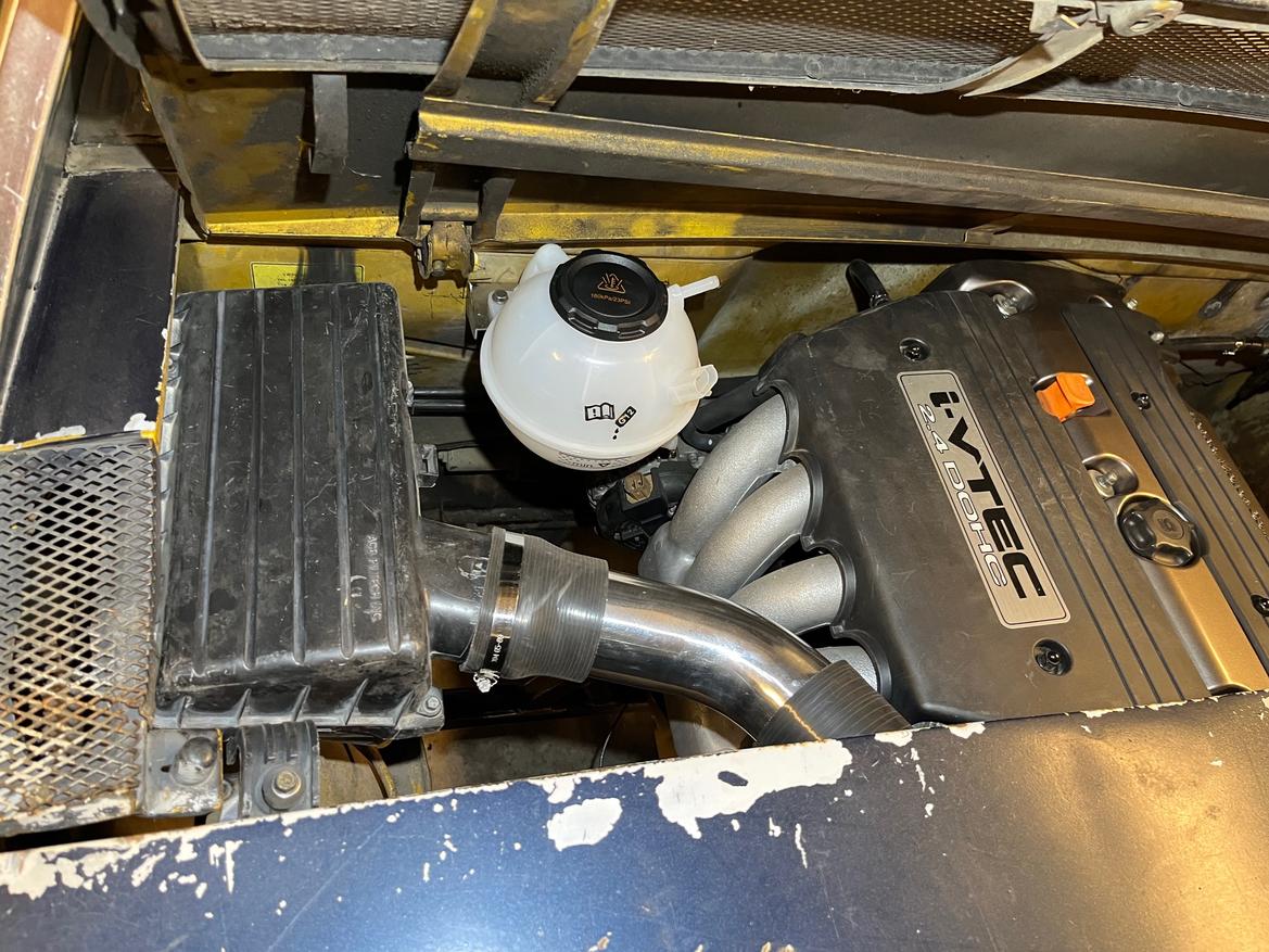


I'll need to do a little bump out or notch for the elbow of the intake but hopefully can tighten up the valve cover hose. I've got a plan for that already.


The aluminum 45 will get painted black or wrinkle black. It shines through the engine cover more than I like.


I love the factory air box. Lookin really good!
In reply to Lof8 - Andy :
Thanks! Yeah it's looking like it belongs there and should still flow plenty for my application I think.
I told myself and the family we needed to wait a year before considering a new dog after Charlie passed. Well I caved and we got ourselves a new puppy!
Meet Archibald McGee AKA Archie


We picked Archie up last Wednesday evening and have been getting acclimated. He's a rescue and is the best puppy we have ever had. Training has been so simple we keep waiting for a rug pull. In fact I'm in my office right now and he's sleeping next to me. He's eager to please and is a velcro dog. I go somewhere and so shall he. It's awesome. We really had a big hole in our hearts when Charlie left us and now it's nice to have someone trying to fill those massive dog shoes.
Anyway, with Archie's recent arrival it has meant a delay on any work for the 914. I'm not mad about that in the least but I did finally manage to pepper in some time Sunday. Weather was excellent and I wasn't particularly motivated to do anything specific so I decided to finish pulling the wiring harness and dash frame from my car as that's where I left off. Wires just dangling out the bottom of the dash since I was struggling to get the damn light switches to come out without damaging them. The lower section of the dash frame was banged up and dented, so some hammer and dolly work was employed to straighten it up.

After getting it square I fit it back into the car to make sure it actually bolts back in place. It actually fit! That felt like a good stopping point so I started to clean up.
When I opened the garage door it was glorious. The warmth, the sun, oh my! It was a sign to do work outside. So I pulled the car cover off the parts car and finished removing the wiring harness. I also swapped over the hood cable and guide since mine was cracked and broken up into pieces. The HVAC box and associated bits were pulled from the donor as well since I managed to damage some parts of mine when removing. Luckily those came out without a fuss so I should be able to make a combo of parts work for me. I also pulled the headlight motors since mine have some wiring hackery going on that I don't trust.
I was kinda in the zone so not really many pics were taken. Honestly there isn't much to see but look, there's a harness on the ground that's complete next to the hacked up one from mine. That is neat.

I couldn't stare at it too long before the cloth tape was removed with a seam stitch cutter. It may be the perfect tool for this kinda job if the tape isn't layered too thick. I used scissors for those areas or just a quick unwrap .


After going back and forth between the janky harness and donor, I realized there are some key differences betwix the two. Especially at the ignition and wiper switch. From what I can tell it's close enough that I can move wires around or splice to match if needed vs having to swap columns.
Right before bed I decided to start pulling wires that will no longer be used. I have a diagram whipped up for what I need to have left over and the original diagrams to show me what I'm pulling actually should be removed. So far it's working great and I think once I update the fuse block to a blade style I'll have a good harness. One thing I will do is replace ALL of the spade connectors with new ones and where possible add in some multi pin connectors to ease servicing. Once I get a good list together I'll probably order a bulk weather pak style or similar kit. Any recommendations would be truly appreciated as I want a good seal but also not too bulky of a connector. They also need to handle the amperage the circuit will have.
So far here's the list I started:
tail lights - 5 pin
head lights - 3 pin
headlight motors - 3 pin
front turn signals - 3 pin
wiper motor - 4 pin
wiper switch - 6 pin?
blower fan - 4 pin?
hazard switch - 7 pin?
light switch - ?
ignition switch - ?
signal switch - ?
We had pizza for dinner and I played with spaghetti afterwards.
Even with every version of wiring diagram I could find there are some odd differences. On top of that, being color blind sucks for this kind of stuff. My wife has always been a tremendous help in that department, but often times I can trace wires back to their origin.
I'm slowly whittling away stuff I don't need as well as getting a feel for how I want to "enhance" this harness.
The wiper motor and ignition stuff are about all I have left to sort. It's all there but I'll be updating the connectors so it's easier to service.
The female spades are pretty brittle so all of those need replaced.
I'm still undecided on which direction to go for the fuse block. A 12 fuse is factory but I found a 16 that I think packages well and would be easy to configure since it has rear entry spades like the stock 914.
I'm not a fan of the relays used, so I'll probably reconfigure for standard 4 or 5 pins.
The factory relay and fuse board in the engine bay won't serve much purpose for my needs. There are a couple wires that need extended or just spliced to get rid of that monstrosity for the reverse light.
The only real circuits I need to add are the fuel pump, cooling fans, fuel sender, dash power, and ecu power. Most of those are ready to splice with the universal harness that's sorta pre-wired. I just need to see how I'll run the main relay when activating the chassis harness and the engine.
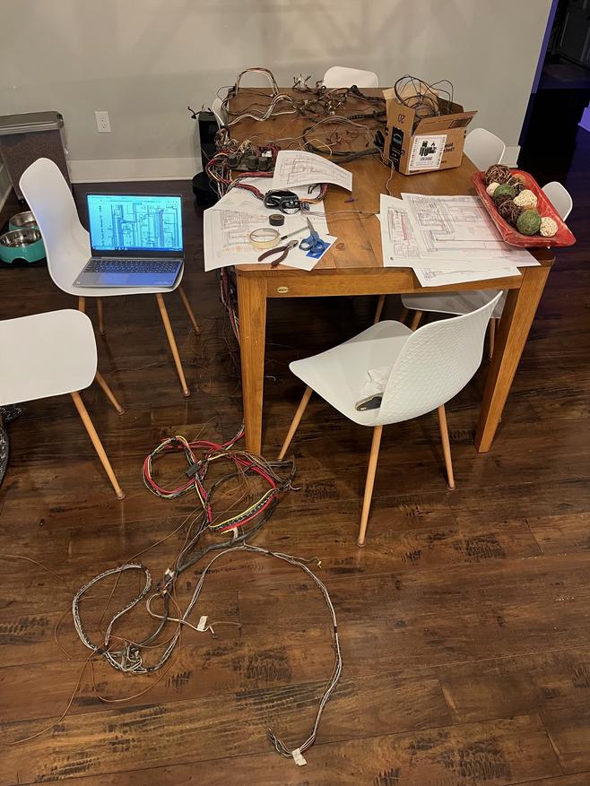
I spent a good half day starting to integrate the newer parts car harness into my 1970 one since there were some changes on the switches used. I want to keep the 70 switches because I have them but also because the steering column dictates what I can use. I mentioned before there are differences but I couldn't find a diagram that reflected those changes. Wire color, routing, and even labels on switches were different but SO similar. The donor car is a 73 and for whatever reason isn't in the list of manuals I found. Anyway I found the correct diagram the next morning and spent a day photoshopping out all of the circuits I will no longer need so I'll have a useful diagram for this car. When I got home that evening I confirmed the work I put in the day before to be correct since I was pulling and moving wires somewhat blind by tracing them back before committing. Had I had the correct diagram from the beginning it would have been so much less hassle and done in an hour or less. Oh well. I've started the planning process of integrating the circuits I need to add in which needs the proper pins and connectors. Those have been ordered so I can take a break from wiring. Sort of. I need to decide on battery and Haltech location.
It doesn't look like progress but this wiring harness is a HUGE step forward. I keep having to remind myself of that as there's no visual payoff with this stuff. If I had planned a bit better I would have spent more time in the garage doing stuff over the weekend VS spending most of it sitting with my laptop making sure I'm ordering the right parts to finish the wiring. I could have ordered that stuff today while sitting at my desk which wouldn't have delaying me much at all in that regard.
And since a post without pictures is not really cool, here's the new "seconds" tail lights I found on ebay. They have some minor scratches on the driver side and maybe a little on the passenger side but they aren't going on a perfect car anyway. For $75 shipped I couldn't complain. Non defect sets will set you back $250.


I had some time yesterday to tinker. My main mission was to measure and plan out brake lines. The hard lines at the calipers need replaced as well as new hard lines at the master since my new one is routed different than stock. Nothing to take pics of but they are all figured out and hopefully that will be on my to do list for the weekend.
Moving on I started looking at what I need to do for a throttle cable. My initial thought was that it could sneak up from beneath the throttle body but the cable direction would be a 180 to the mount. That's probably something that could be included in the custom line but isn't ideal. The next thing I did was spend time checking to see if I can flip the throttle cam and make cable entry from below possible. If there's a way to make that happen, I can't seem to figure it out.


After staring at it a bunch I realized I can make the cable go around the exhaust side and have a much smoother entry to the cable mount. It's not what I wanted but it's what has to happen I think. If Terrycable can add a 90 bend into the bracket even better for clearance with the trunk lid and soon to be grafted access cover.
With that out of the way I spent time writing down the various measurements needed to order the cable. I'll call this afternoon to see if what I want can be made into a reality.

Terrycable will make one off cables like this? I have a friend looking for a custom accelerator cable for a Sprite. If so I'll direct him to them....
In reply to MiniDave :
Yes they will! Our resident member and fellow k swapped 914er Lof8 - Andy told me about them. I called yesterday to inquire and the lady I spoke with was SOOOPER nice but above all massively helpful. I gave her all the information I could and she said it may take a week to have made. Cost will be $65 before shipping but it was way easier than I expected. I will have an adjustable barrel at the throttle body side and when I get that officially locked into the place I need it can either solder it myself in place or send it back to get finalized. Hopefully I'll have it in my hands in a couple weeks to follow up on that.
Excellent! Thanks....I'll send the info to my buddy.....he's doing a bike efi system on his Sprite
While this thread is back on top I have a few pics to post. I was adding in the coolant bleed line to the expansion tank last night and was admiring how much more I like it without the vtec intake cover. It looks more fitting this way so I think the cover is getting removed permanently.
Hopefully this weekend I can get some more progress done. There's a good check list of stuff to do that should push me further along.


I agree about the cover....looks awesome that way.
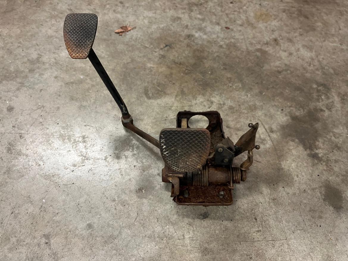
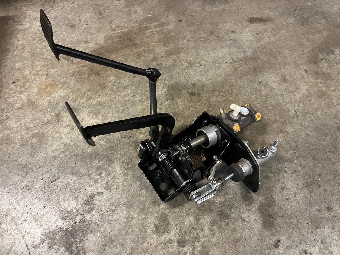
This weekend didn't go quite as planned but I've made some forward momentum. The pedal assembly needs bushings. It also needs the clutch push rod extended, so I started there first.
I welded a nut to the end of a larger clevis I purchased a while back. This seemed like it was long enough at the time but I later found out the clutch spring was broken causing a false reading on pedal play. I also realised I was either out of MIG gas or failed to install my new liner properly. More on that later.

I then trimmed the throttle linkage to clear the new larger clutch clevis.

Things were moving fast and I had a pile of new plastic bushings to replace on the pedal assembly just staring at me. I wanted to pull everything apart, blast it with paint and then assemble the next day. That's not what happened at all.
Everything was coming apart pretty well up until the clutch arm. It has a roll pin locking it to the arm.

After finally getting the roll poin out the arm would not come off the spindle. Heat, penetrant, air chisel, hammering, swearing, and nothing seemed to work. So I decided to grab the pedal assembly from the parts car and see how far I could get with that.
It came out of the parts car so easy I was certain it would be easier to take apart. Except I ended up in the same position. Only to be confronted with more struggles with the roll pin since my tool broke off in the arm...... It sucked. I hammered my hand like 5 times but finally got it freed.
Back to pulling the arm off the spindle. There's no easy position in the vice for any of this. Things are flopping around. Nothing wants to cooperate. Heat, chisel, hammer, more air hammer. I tried a three jaw, then two jaw puller. Nothing would fit quite right. Except this ball joint tool. EUREKA!!!!

Sure enough it started pulling the arm off. The parts car came off with just that tool but the other had to be finished off with a ball joint splitter tool. No pic but with them both taken apart I could finally call it a day.


Sunday I had one mission. Paint the parts and make the pedal assembly whole again.

Having the two assemblies made it possible to select the best available for one super good enough set. I probably should have waited a little longer for the paint to cure but I really wanted to see it all together. I decided to forgo the roll pin and instead use a bolt to lock it in place.


It was at this point I realized the clutch clevis will need to be longer. I bought a longer threaded nut to weld to it initially but with the broken clutch spring it seemed too long. So I used a shorter one. When welding the shorter one on it was obvious that I wasn't getting any gas and the feed of the line felt really strange. So after taking a break I went back into the garage to investigate my MIG gas problem.
I found a couple errors on my part, mostly due to me just rushing through the install with zero preparation involved. The liner was sticking out too long blocking the gas passage in the gun nozzle which was my major problem with porosity and lack of gas. After trimming that up I still couldn't get a consistent wire feed. This is why I decided to change to my spare liner in the first place, but obviously something was not right still. After looking things over again I found that the wheel on the feed should have been flipped for the smaller .025 welding wire. I had seen this before but apparently ignored it completely. With that repositioned we have a nice smooth feed with gas! So glad to have that sorted as it would have kept me from moving forward elsewhere.
To try and accomplish one more goal I decided to assemble the axles. I was already dirty and just wanted to check stuff off the list.

After getting the outer end assembled on the first one I started to reboot and pack the inner. It was at this point I realized I was missing a circlip. Mother of frick! I dug through all of my parts boxes, totes, bags, etc. and came up short handed. I was frustrated enough at that point to call it a day and track down a circlip to finish at a later date. I probably should have just finished everything but the one end but maybe that can be tonight's progress instead.

Last night I spent a good half hour just cleaning up the garage. Soon I need to reorganize my tool cabinet. I've got drawers packed to the gills and 80 percent of it barely gets touched. A bench style toolbox addition would probably help a ton but all my money is getting thrust into the 914 so it can wait.
After a good clean up I got the battery mounted. I've been eye balling a spot near the stock 914 battery tray and there's a bracket on ebay that should fit my battery. Even better it was only $28 shipped. It's lightweight aluminum and nicely bent. I couldn't make anything as nice as this, so it seemed like a no brainer.

As you can see it needs a little trimming to make room for terminals.

After positioning where I wanted it and making a couple marks, it was time to rivnut. To the left you see there's only one in place. What you can't see in this pic is that the sheet metal dips in where the next two upper holes would go. When I pull the engine out the last time I'll make a sheet metal bump out for it to fasten to.

And now with a battery installed. It's nice and snug. Stock battery location means my wiring should reach without issue. Pretty pleased with this setup.

It's not terribly difficult to install but not exactly easy either. The bracket captures the battery so it needs to be bolted in together at the same time. I figure it's not going to be in and out much so it will be fine. I also think it will end up black or whatever engine bay color I settle on.

I had time to knock one more thing off my list. The typical feed line on the gas tank is an oddball size thread. Since I'm no longer using that port it needs to be plugged up. There are some adapters to AN fittings where I could use a cap over it but that seems silly to adapt a part to then just cap it. So when researching what to plug it with, there was mention of folks tapping the inner section of the feed for 1/4 NPT. So that's what I did. Tap it and then an allen head plug to block fuel from getting out. Nice and tidy. Cost me pennies. Took me less than 5 minutes to do. Can't beat that.

Axle circlip should be here tomorrow so my main goal will be to finish assembling the axles.

captainawesome said:I kinda needed something to really wrap up the progress for the weekend and make me feel like I accomplished something. A while back I found that Gates makes these heat sleeves used on coolant hoses. I thought they would be perfect for the splices I have in the system so I won't need a half dozen hose clamps. RockAuto had them for around $3 each so I bought enough to do the whole system other than the actual connection points that will be serviced.
Let me tell you boys and girls, these things are worth every penny!
I'm glad this thread came up. I was thinking about these yesterday. Do you know if they are available in a 5/8-ish range? I'd like to try them on some air hose repairs.
Edit: I don't know why I bothered asking knowing I was immediately going to Google them as soon as I knew what they were called. 😅 I suppose I should have just thanked you for sharing.
In reply to Crackers (Forum Supporter) :
Whether your 5/8" measurement is ID or OD it depends. Here's good chart of what's available though. I'll be using 32925 for my heater core hose splices.

Folks.
Calm yourselves.
Let it be known.
We have axles.
Axles that are assembled.
Axles that are ready to party.

You'll need to log in to post.