Now I see..with the bullet in the cradle and lining up the front suspension points = No Bueno Vato
It would be technically mid engined if i was able to keep the engine in that position, but alas, just not meant to be.
Im in love with the portaband though. One of tbe best tools in history.
Challenge budget so far:
previous challenge budget: 780.62
recoup total: 800
new money:
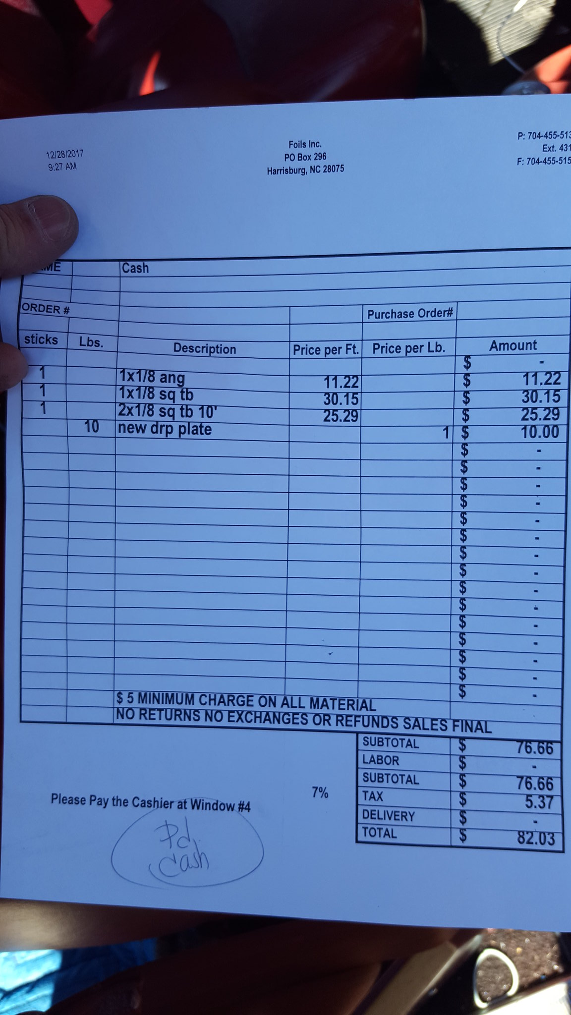
20 feet 1x1x1/8 angle iron: 11.22
20 feet 1x1x1/8 square tube: 30.15
10 feet 2x2x1/8 square tube: 25.29
10lbs 1/8 plate steel: 10.00
modify oil pan: 8 according to steve
jb weld: 2.50 (6.99 pack, used about 1/2)
new total: 868.78
to start with, I figure well talk about parts acquisition.
I finally got stuff picked up and pictures taken of parts that I talked about, but didn't document proof of.
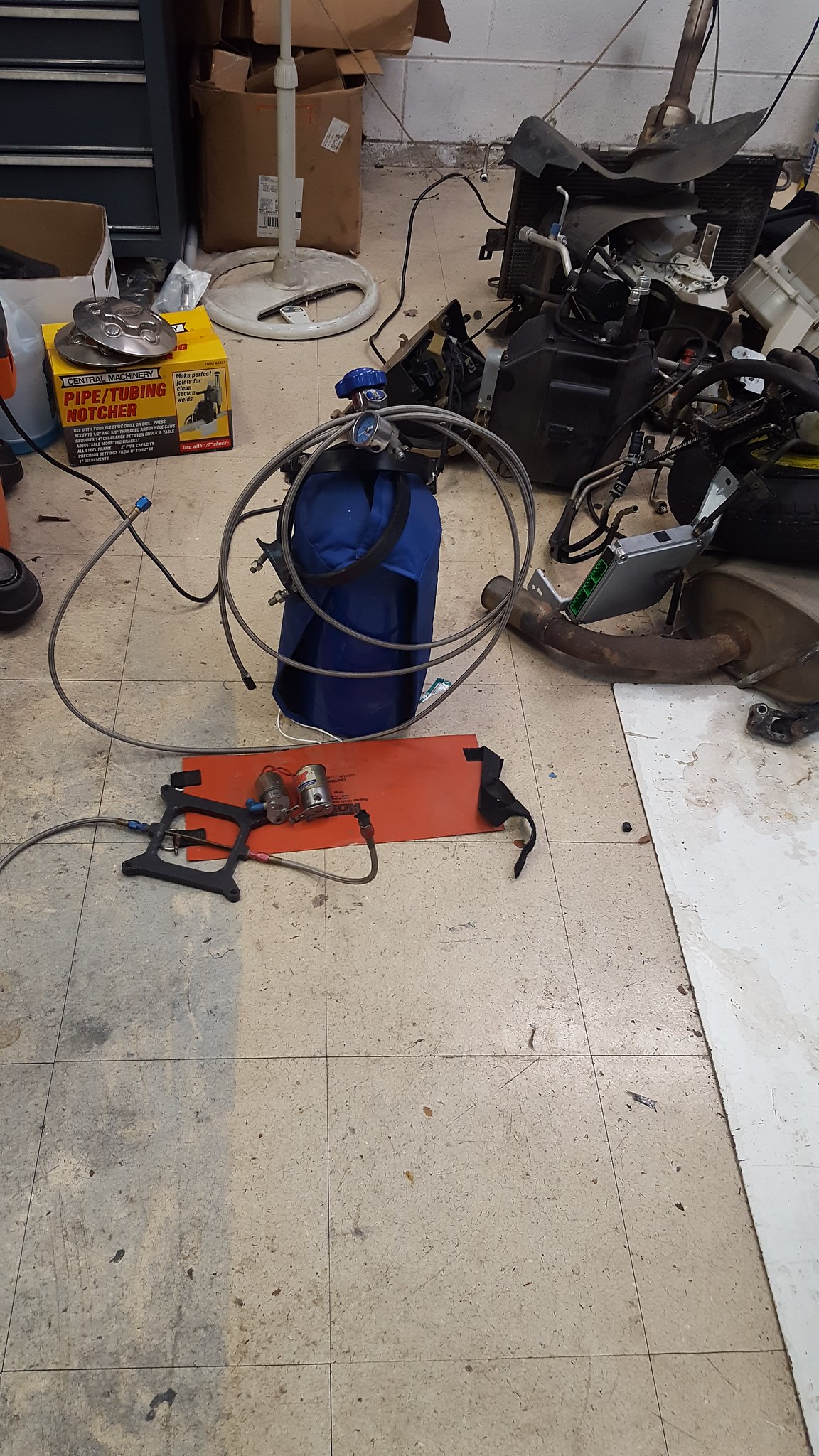
Nitrous kit from the trailer park yard sale:
 20171206_075641 by Michael Crawford, on Flickr
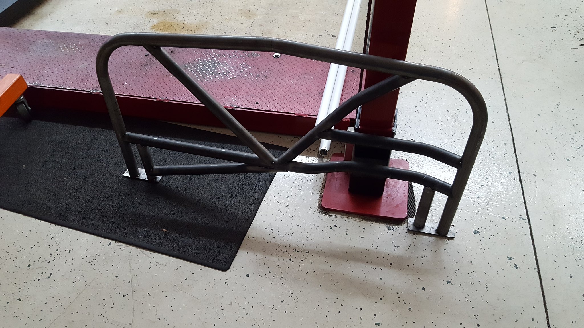
spec miata cage (still have to grab the roughly 20 feet of tubing he has but couldnt find when I was there)
 20171229_164854 by Michael Crawford, on Flickr
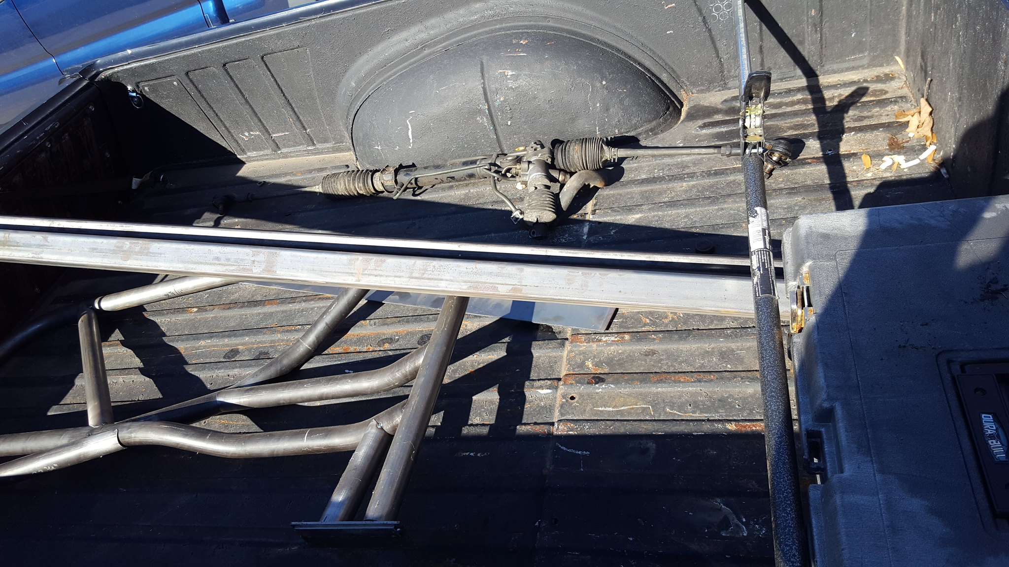
steel order and steering rack
 20171228_113010 by Michael Crawford, on Flickr
 20171228_113017 by Michael Crawford, on Flickr
slicks (drove 150 miles like this. Stampie drive far greater. Hes cooler than me)
hoosier is my co-pilot
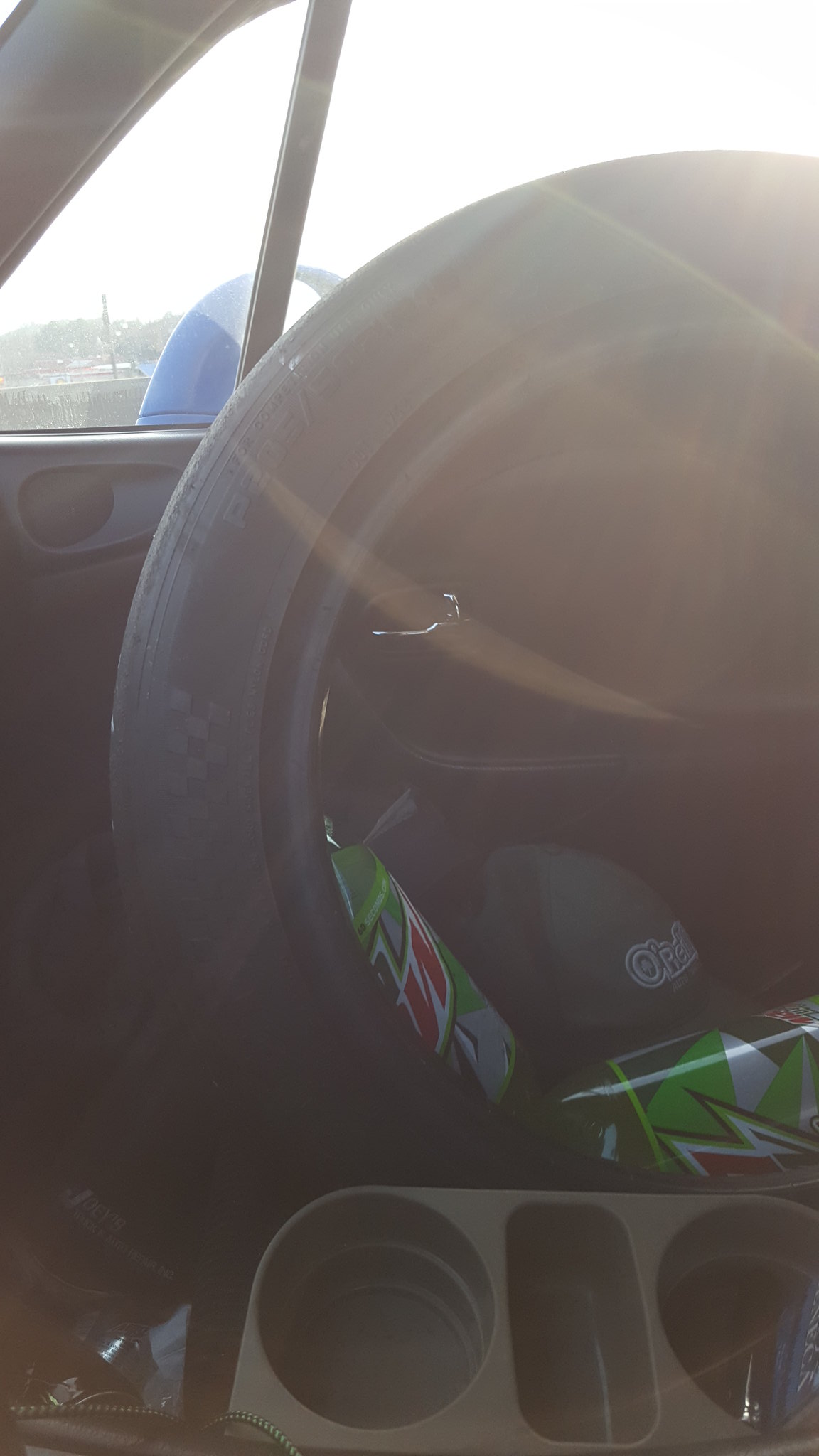 20171229_155119 by Michael Crawford, on Flickr
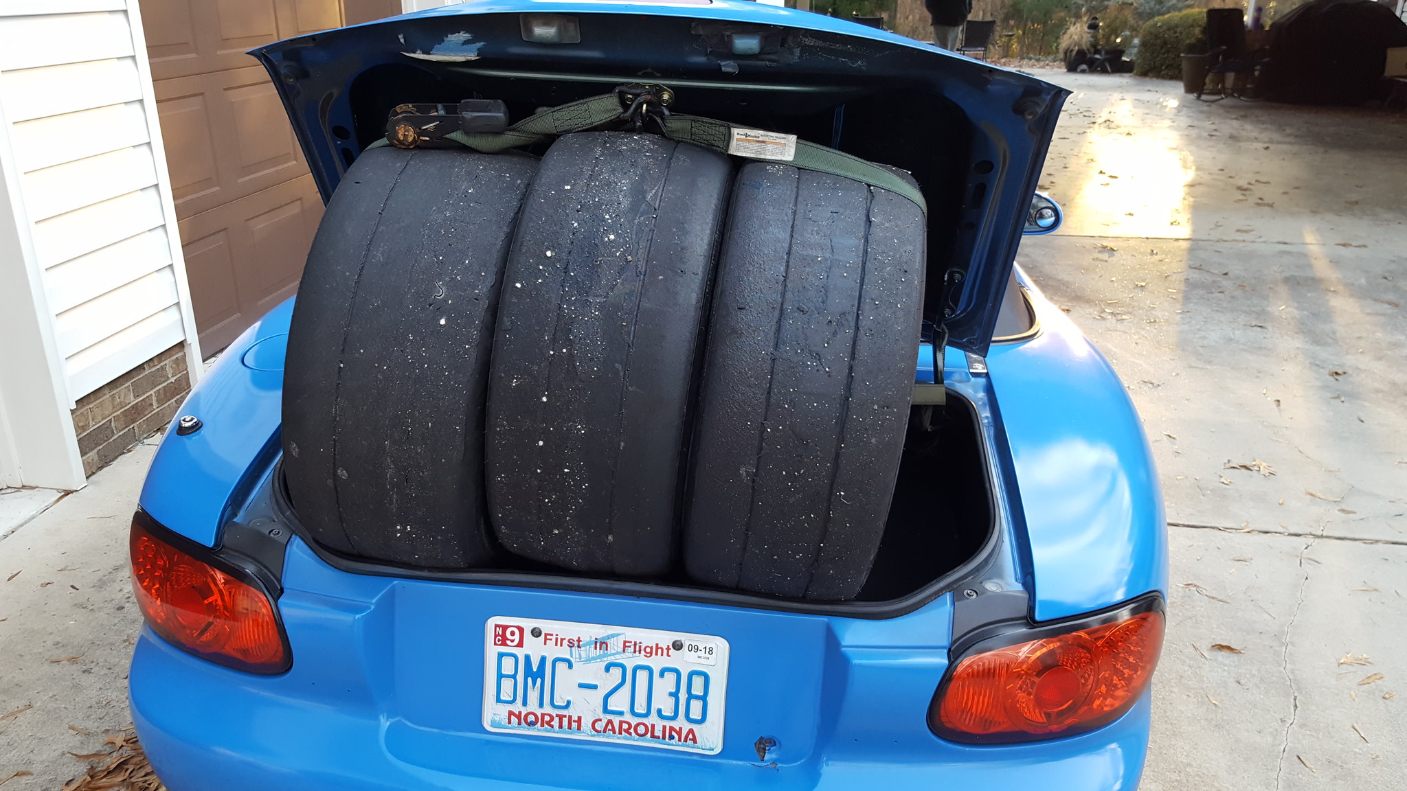 20171229_164443 by Michael Crawford, on Flickr
wheels:
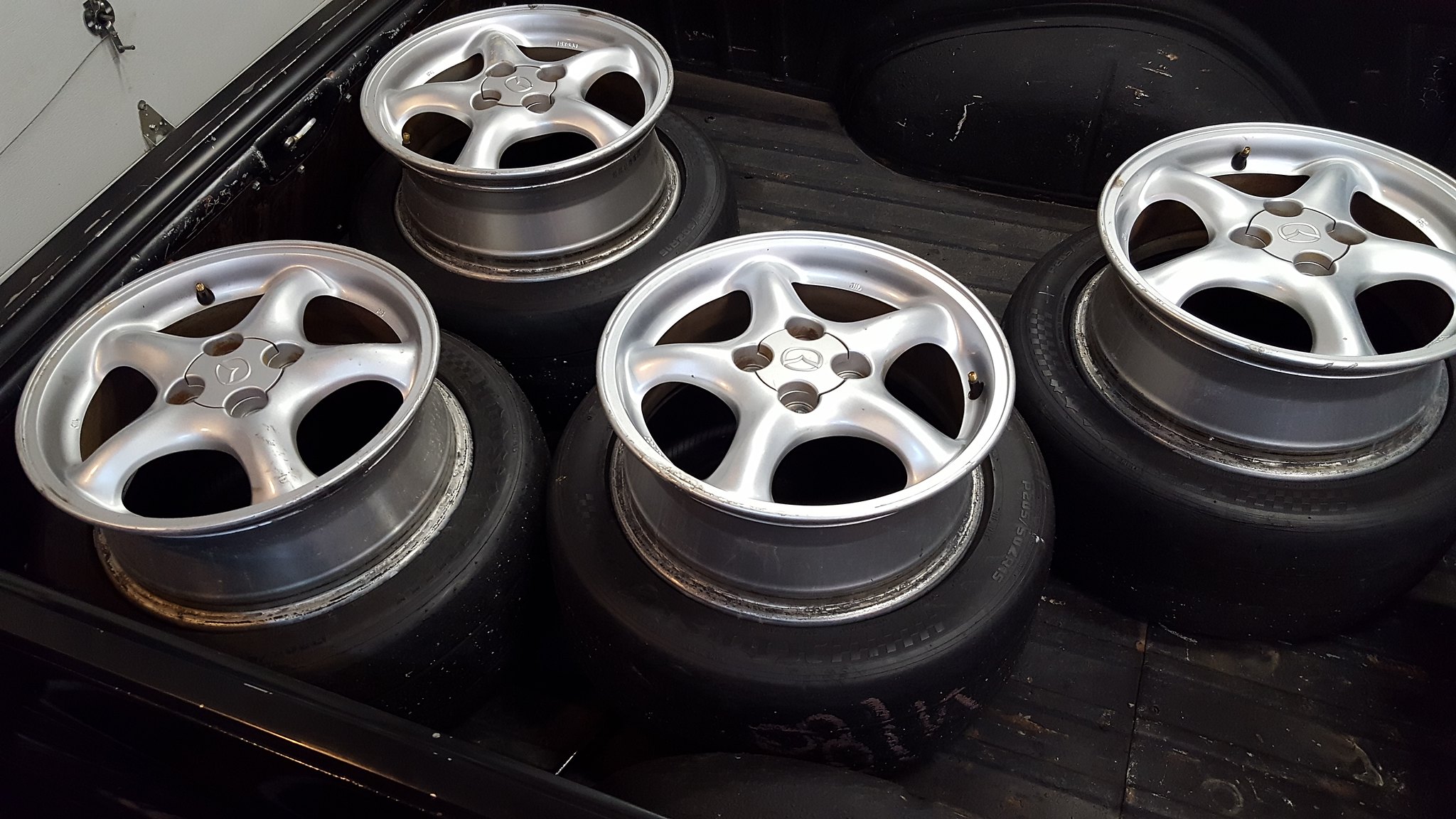 20171229_180558 by Michael Crawford, on Flickr
ok. now that that's out of the way....
I had decided when we left off that either the crossmember needed to be radically restructured, or the oil pan. We were about 2 inches shy of where we needed to be. The decision came down to notching the pan AND the crossmember. Pan first.
Stafford1500 (steve from last years challenge car insanity) offered to cut and weld it if I got it clean enough and brought it to him. So we pulled the pan off, and after about 6 freaking hours of cleaning with screwdrivers, wire brushes, superclean, oven cleaner, and a pressure washer, it was clean enough for me to work with. Steve said that it was far cleaner than it needed to be for what we did.
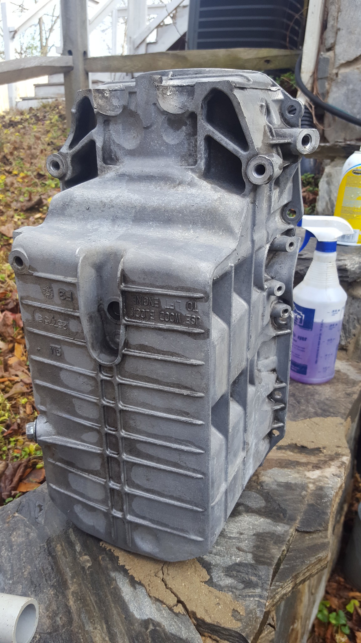 20171226_104428 by Michael Crawford, on Flickr
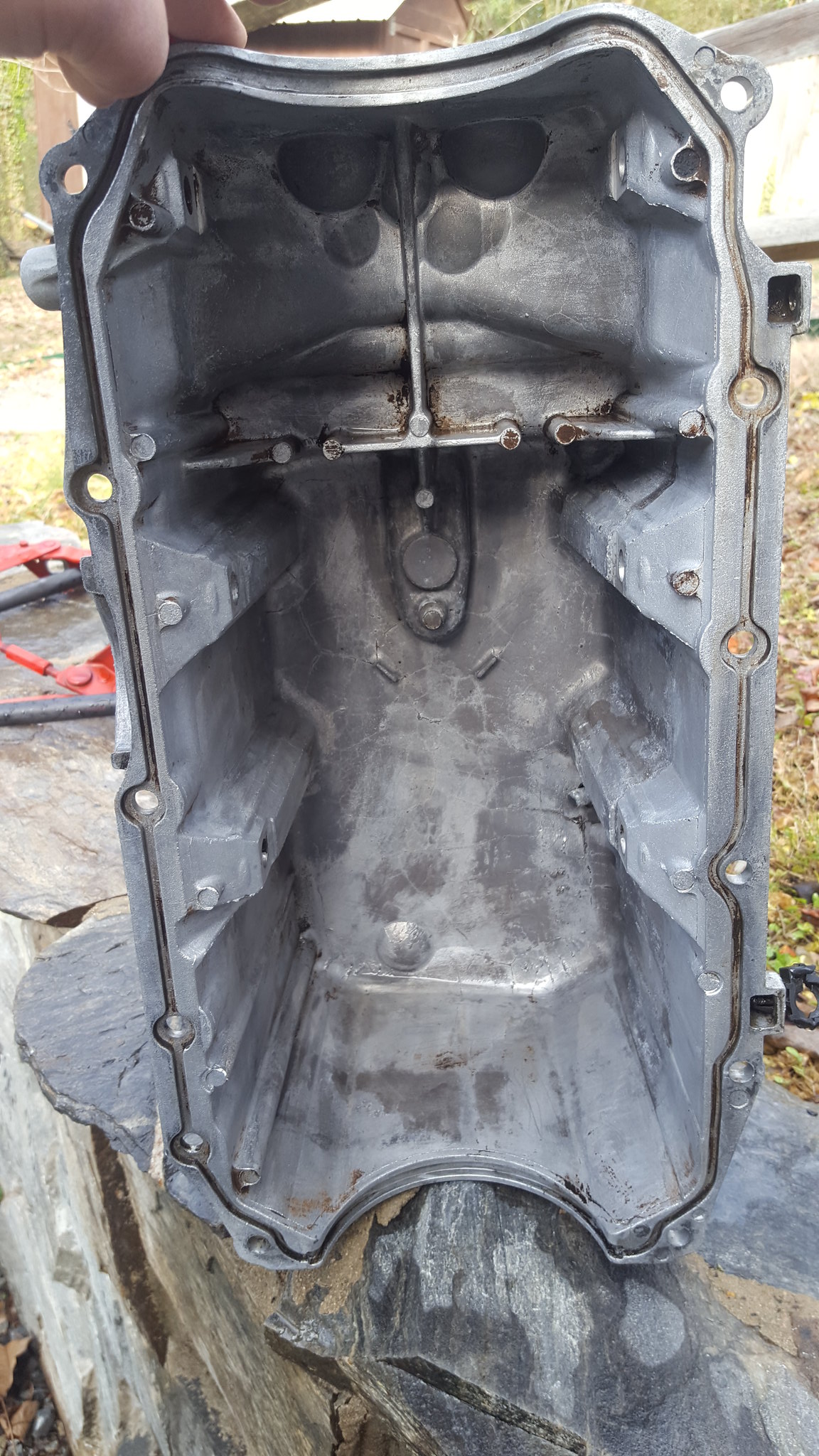 20171226_104437 by Michael Crawford, on Flickr
Anyway, we marked out a 3 inch notch with a sharpie, and mounted it to steves surface plate. He proceeded to cut the majority of it with a handheld circular saw. With a wood blade. At face level. BALLS.
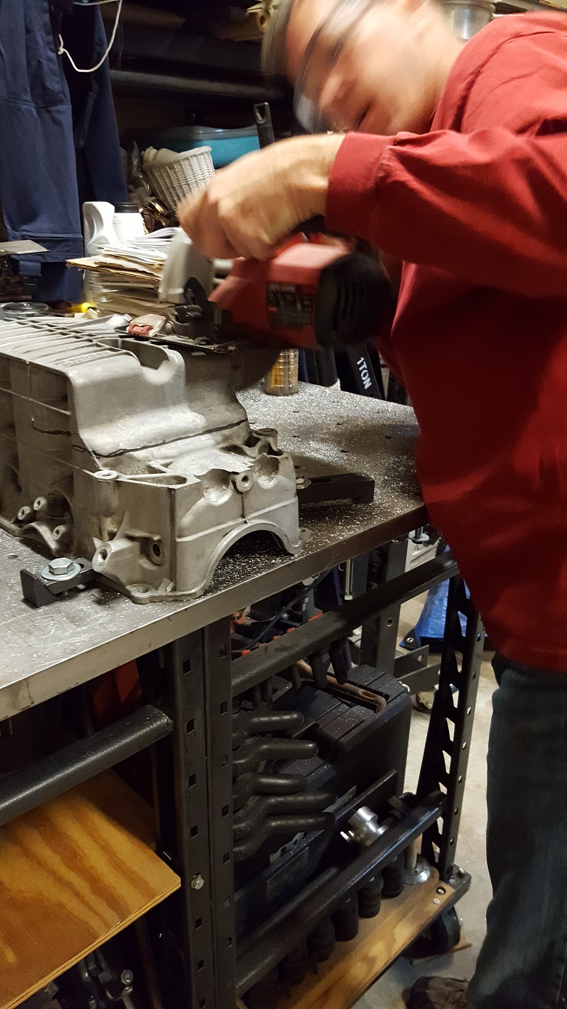 20171228_104826 by Michael Crawford, on Flickr
we dressed the edges with a flap wheel, emery paper, etc. while I was doing that, Steve cut a chunk of aluminum plate from a sheet that he had standing in the corner of the shop, after making a good cardboard template. Steve has so many awesome tools at his disposal. And such neat projects of his own. Makes this project look like a carburetor rebuild.
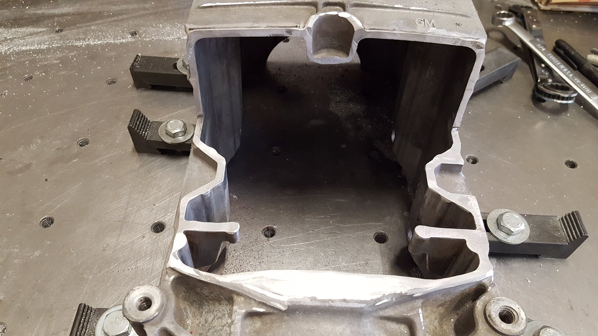 20171228_112855 by Michael Crawford, on Flickr
after getting the plate cut and fitted, we ratchet strapped it down and steve welded it up. (I say that like its easy. TIG is freaking black magic. Two hands, a foot, and talent all at the same time. I can barely chew and breath at the same 10 minute span.
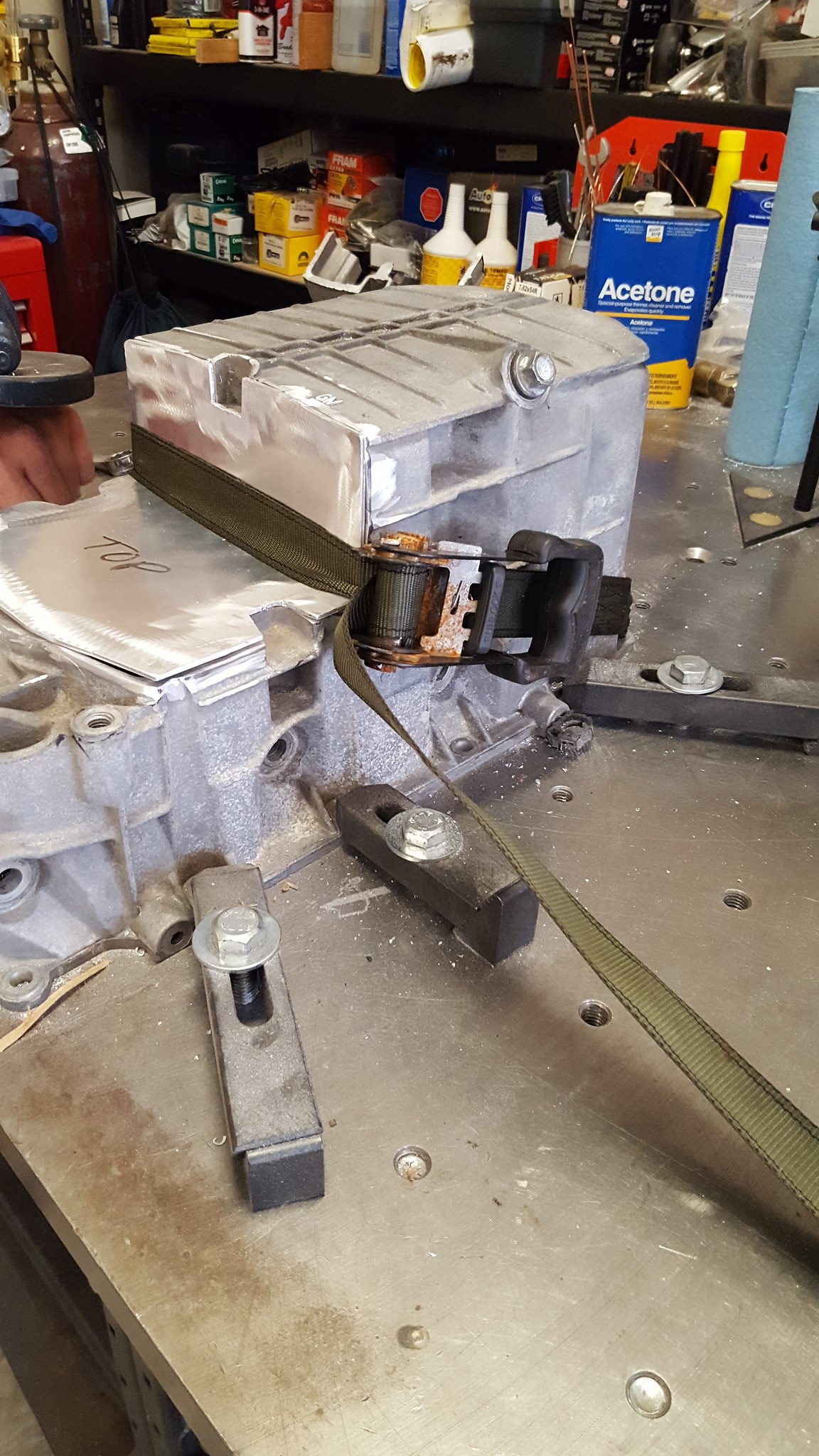 20171228_123837 by Michael Crawford, on Flickr
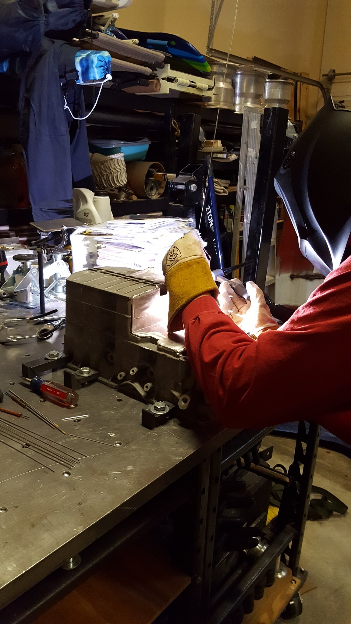 20171228_133335 by Michael Crawford, on Flickr
when we got all finished and unbolted from the table, we found that there was very minimal warping. Like .002 corner to corner on the rails. Close enough!
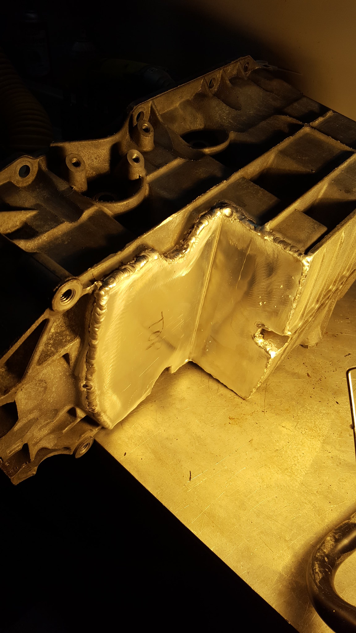 20171229_164831 by Michael Crawford, on Flickr
Took it home, and decided that since im a belt AND suspenders guy, it “caulk” the inside of the pan with jb weld reduce the chance of leakege. Stopped by oriellys and grabbed 2 packs of the good stuff.
 20171228_163917 by Michael Crawford, on Flickr
took it over to dads place, where he promptly took over. He custom cut a few popsicle sticks, and caulked every seam in the pan with ½ of one pack of jb weld.
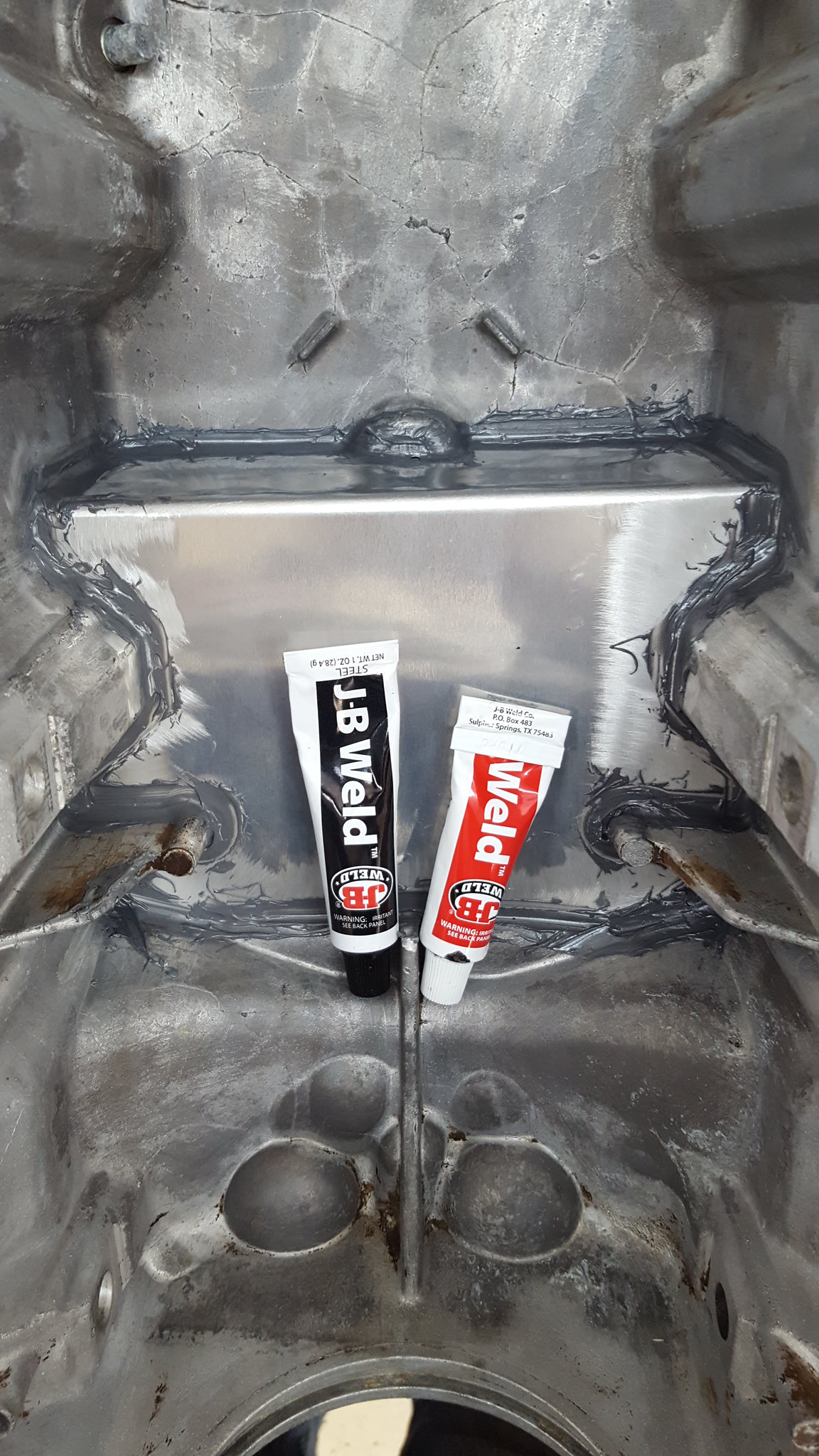 20171230_090109 by Michael Crawford, on Flickr
that brings us up to today. After the weld fully cured, we bolted the pan back to the engine. It cleared the stock oil pump pickup, and all the holes still lined up. Definitely successful....
I also noticed that this engine has a factory windage tray. Which also cleared! Score on both counts!
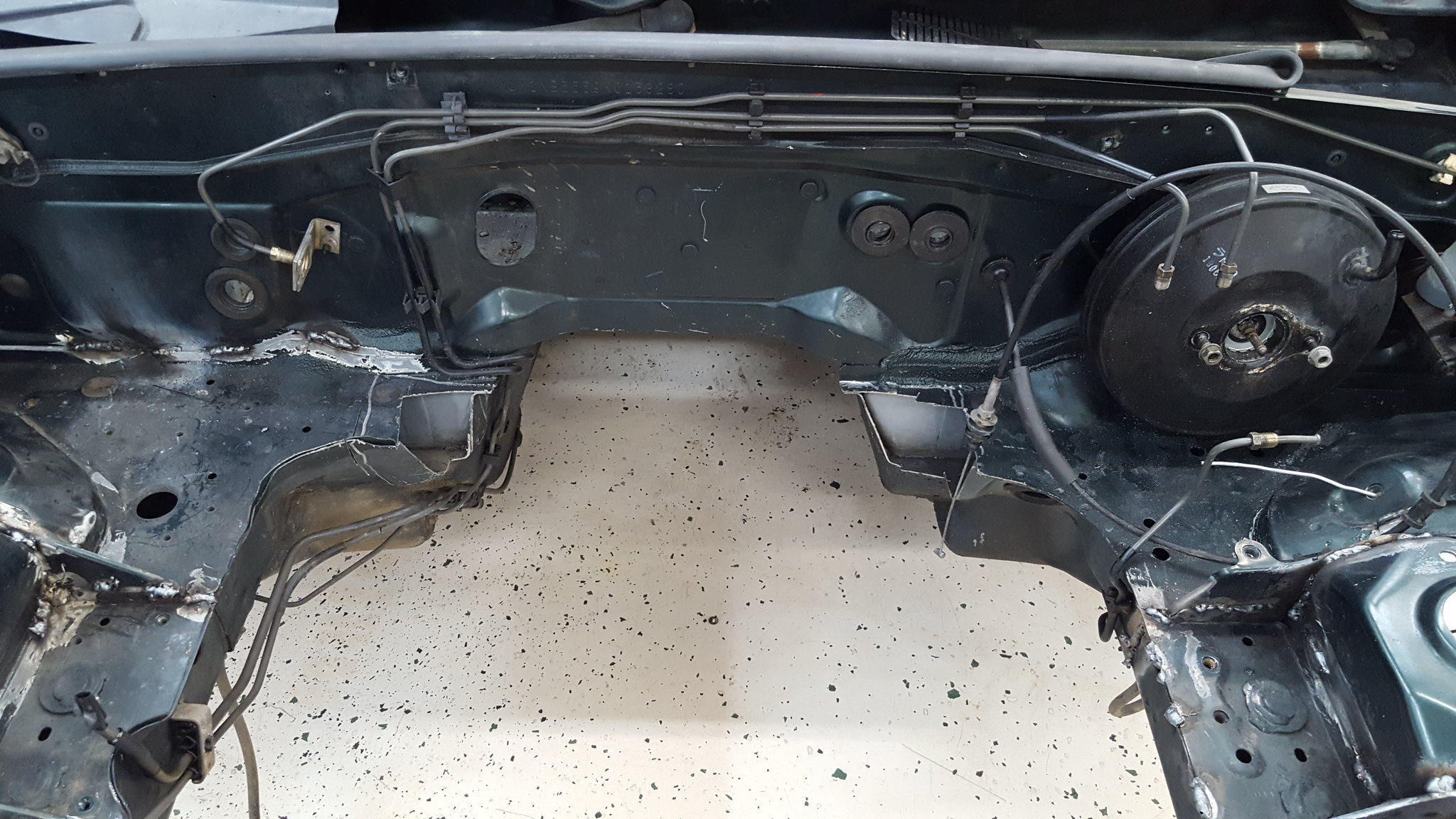
I did finally take a picture of how much I notched the crossmember. There's a little clearanceing on the flange on the drivers side to do, but that's purely for piece of mind. I've got about ¼ at the tightest spot. We have also nipped the edges of the wings like the v8 guys do. Only the drivers side turned out to be necessary. Passengers I just made extra work.
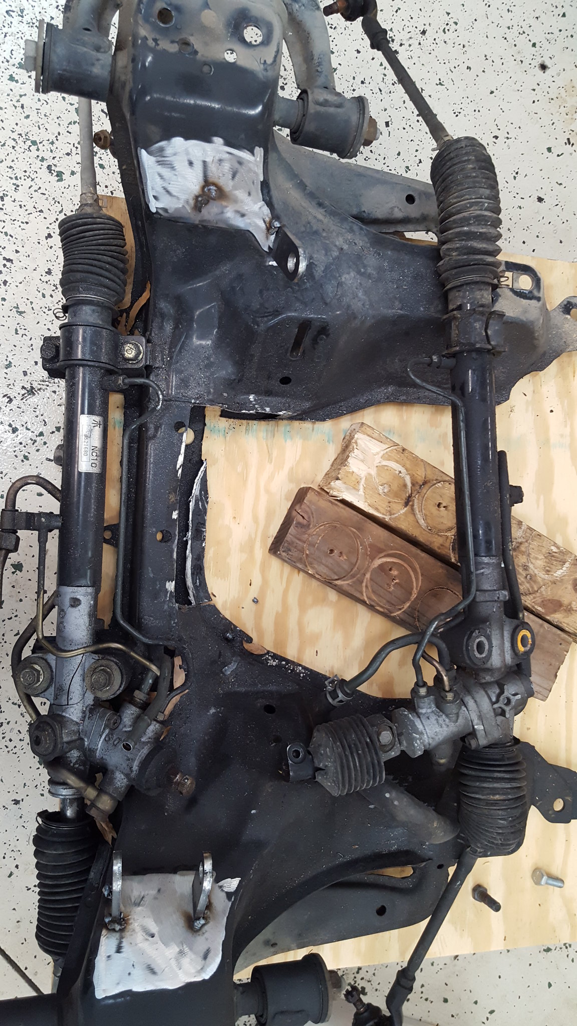 20171230_084705 by Michael Crawford, on Flickr
 20171230_085850 by Michael Crawford, on Flickr
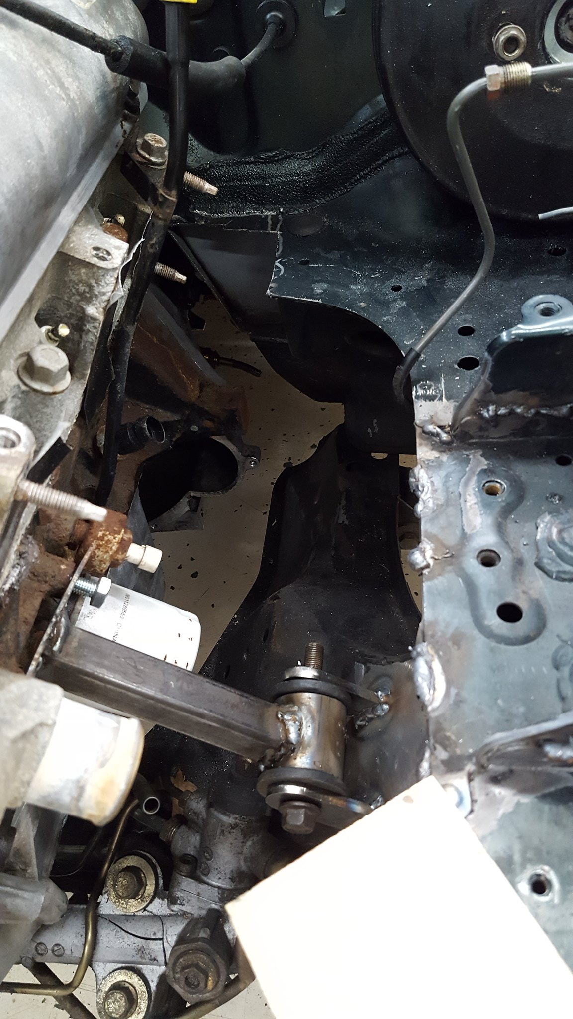
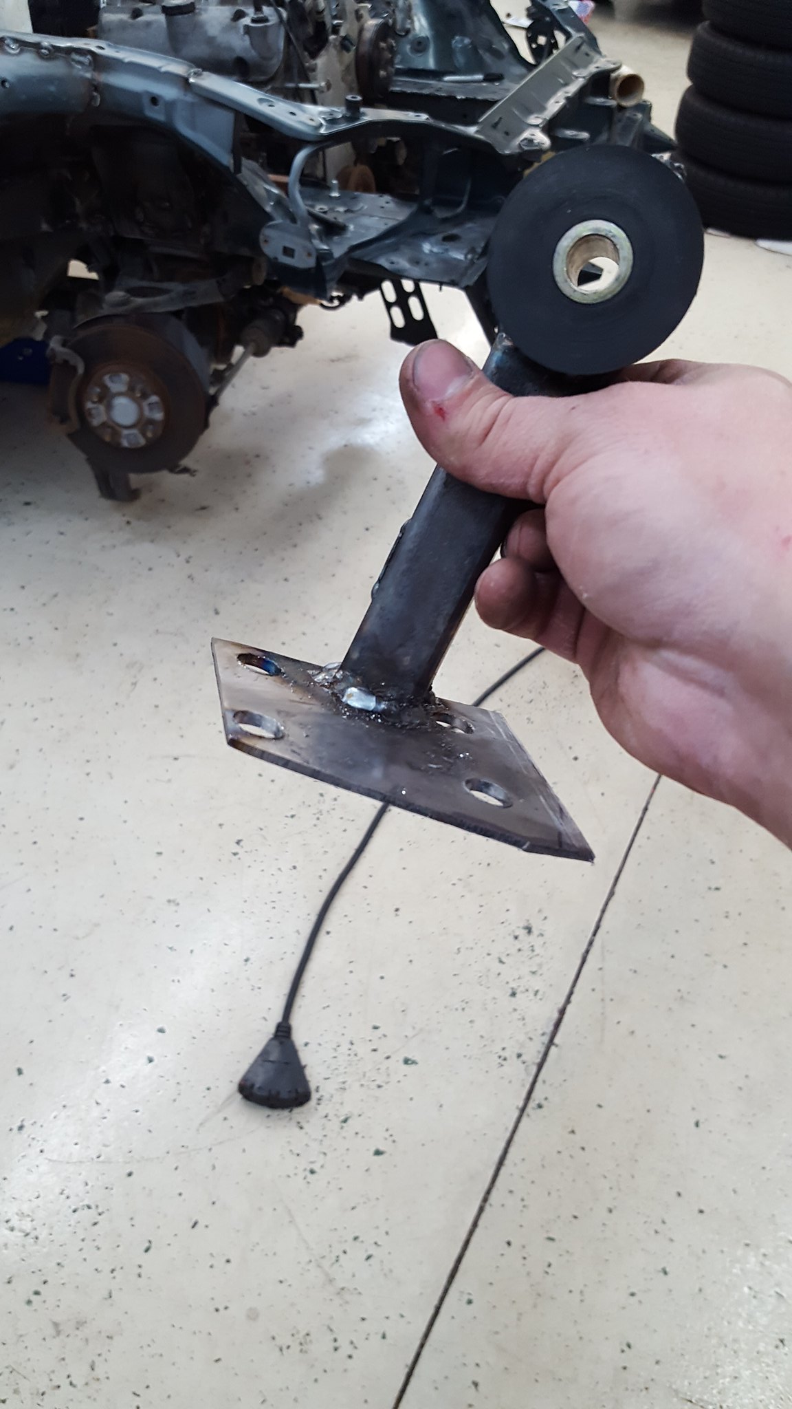
dad and I slipped everything into place. And stared. And readjusted. And stared. And playing with angles. And stared. Eventually we decided we were happy with the compromises we were making, and held the drivetrain in place with a jack and chunks of wood. Then got to making mounts.
 20171230_132202 by Michael Crawford, on Flickr
 20171230_125045 by Michael Crawford, on Flickr
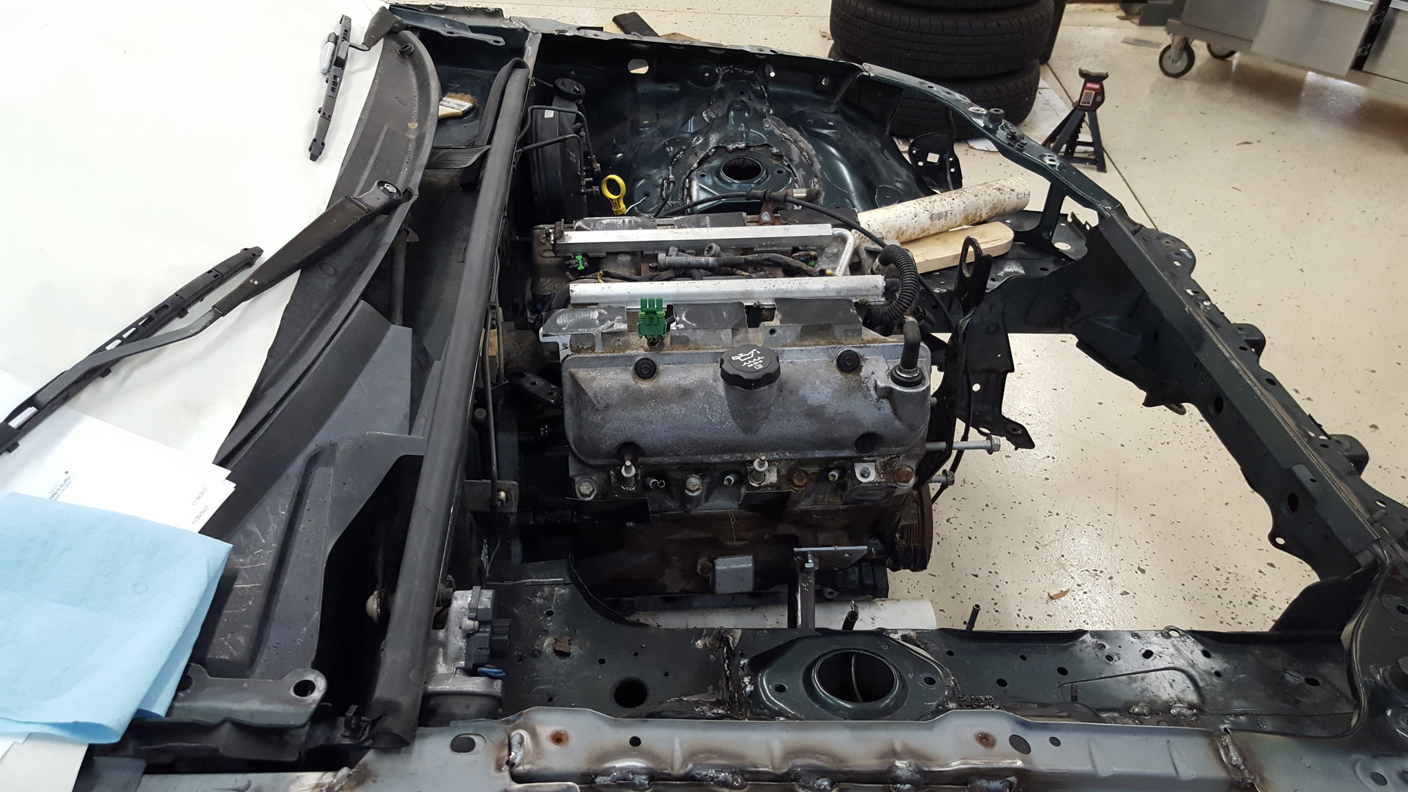
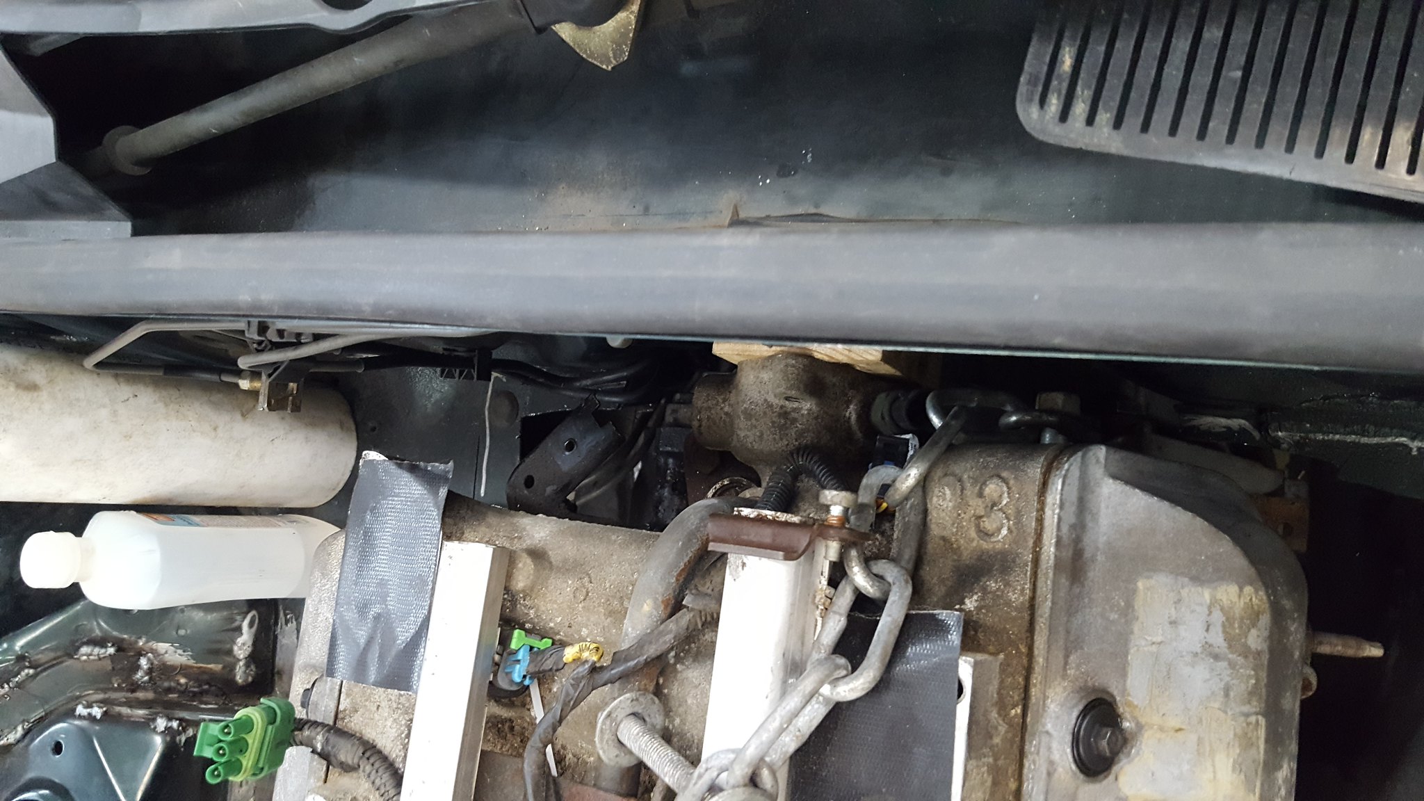
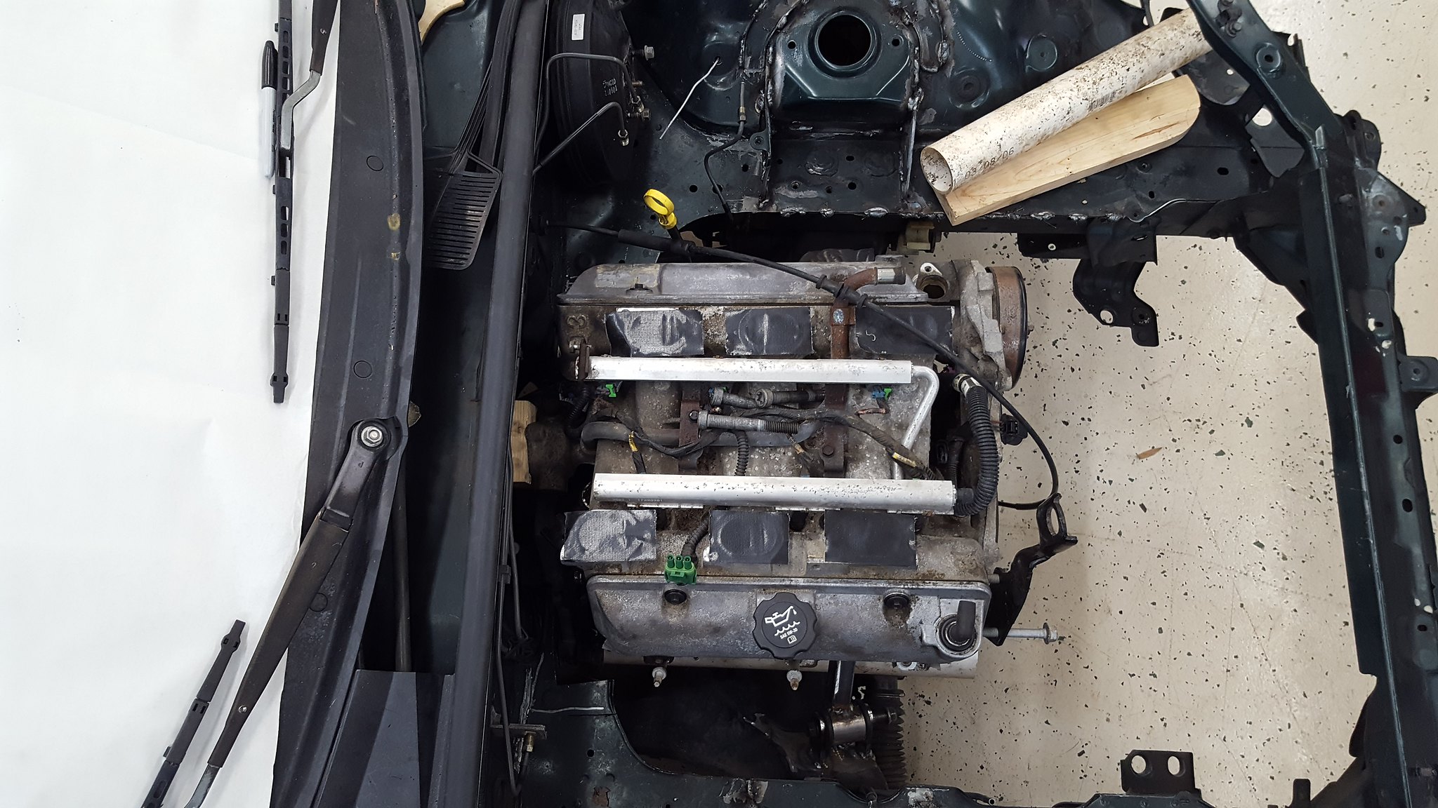
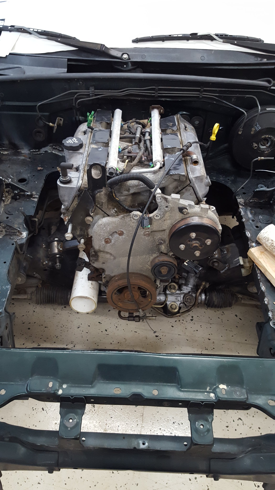
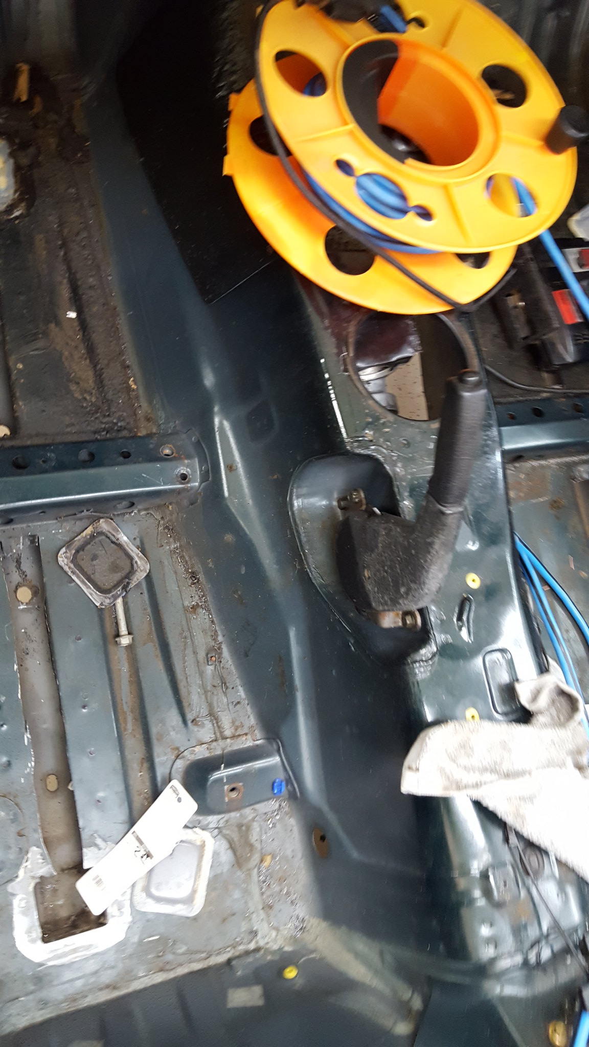
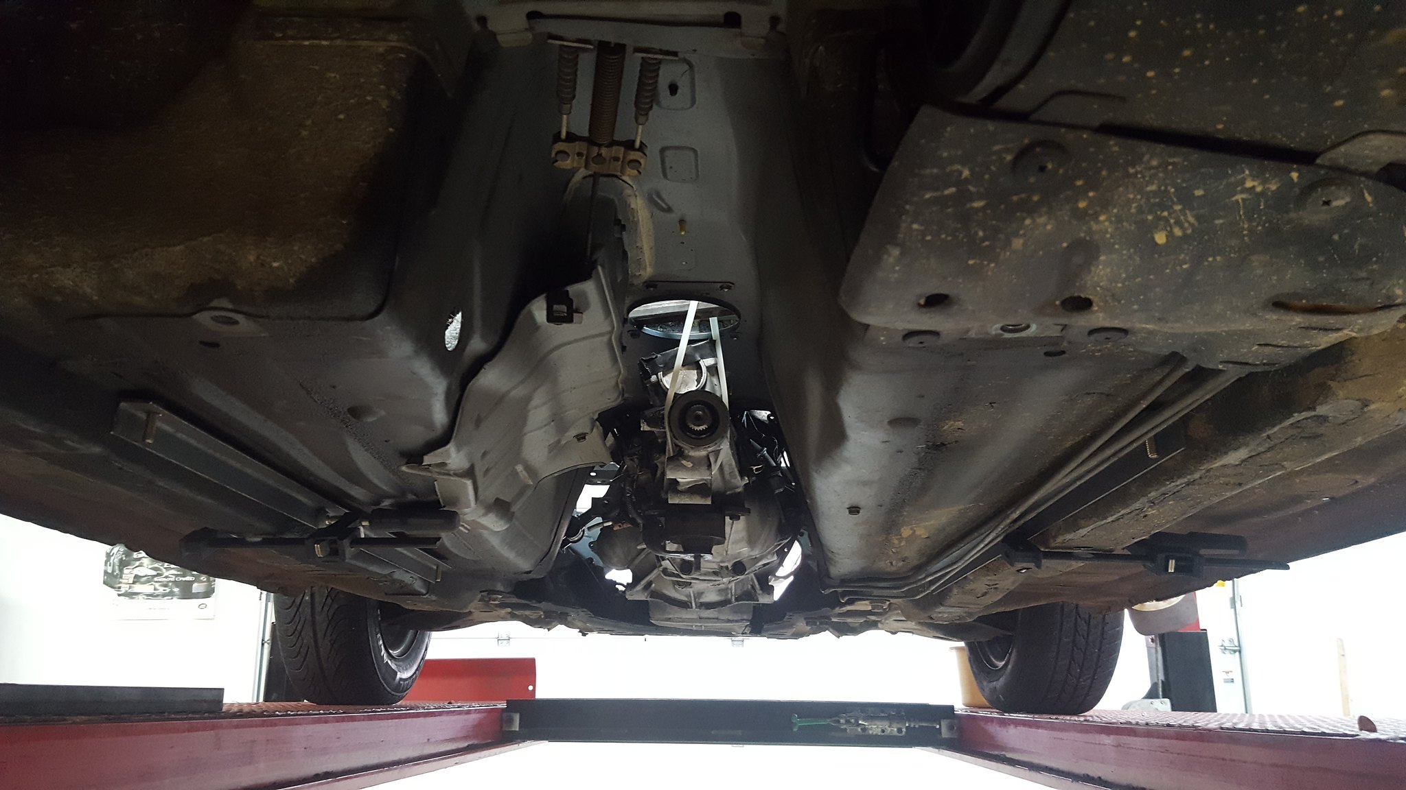
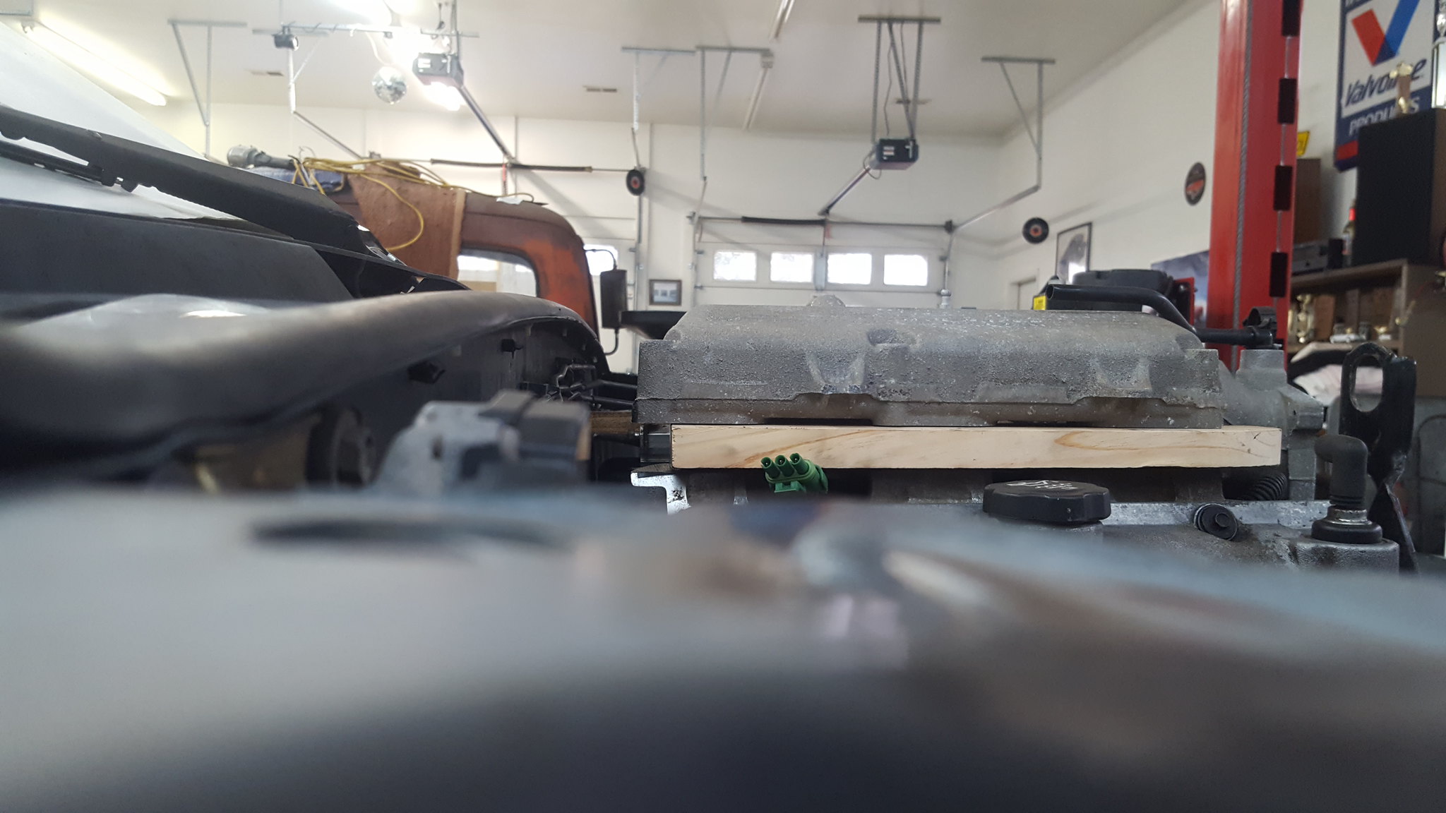
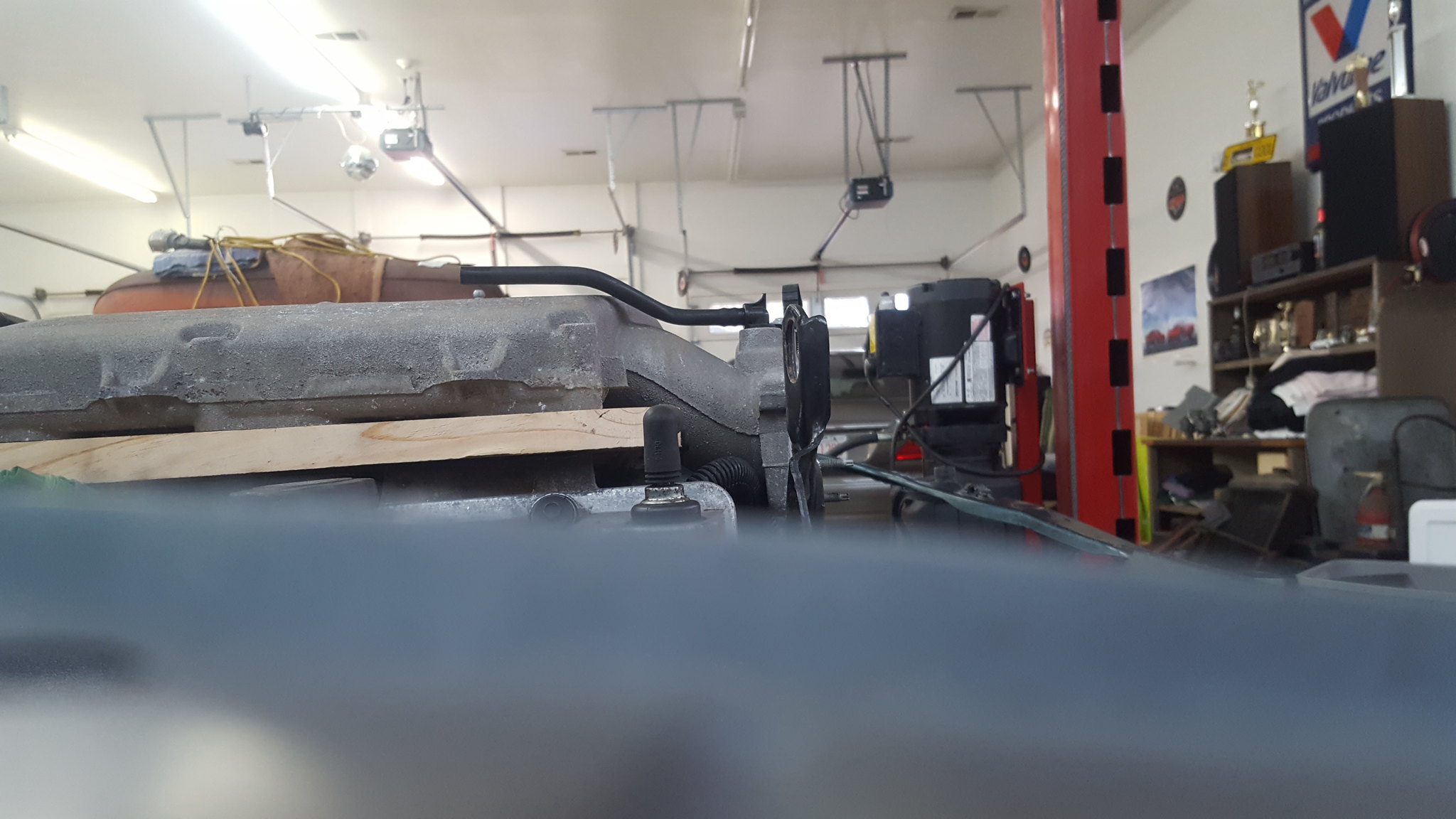
end of the day pictures. Feels like a huge milestone. The intake MAY clear the hood, but no promises. Fairly good exhaust clearance, lower intake in factory orientation with the thermostat hosing above the bellhousing. Mocked up with a block of wood ¼ thicker than the housing to ensure clearance. Passengers side head exhaust port is in front of axle center-line, drivers side is at. It just wasn't worth the extra effort and complication to go slightly further back. Shifter is at the extreme forward edge of the factory shifter hole, so we will have to monkey with some doglegs and such.
 20171230_150404 by Michael Crawford, on Flickr
 20171230_143140 by Michael Crawford, on Flickr
 20171230_132150 by Michael Crawford, on Flickr
 20171230_143202 by Michael Crawford, on Flickr
 20171230_143129 by Michael Crawford, on Flickr
 20171230_113335 by Michael Crawford, on Flickr
up nest is the 2x2 frame rails, and butterfly brace/trans mount. Then exhaust.
Challenge budget so far:
previous challenge budget: 780.62
recoup total: 800
new money:
20 feet 1x1x1/8 angle iron: 11.22
20 feet 1x1x1/8 square tube: 30.15
10 feet 2x2x1/8 square tube: 25.29
10lbs 1/8 plate steel: 10.00
modify oil pan: 8 according to steve
jb weld: 2.50 (6.99 pack, used about 1/2)
new total: 868.78
to start with, I figure well talk about parts acquisition.
I finally got stuff picked up and pictures taken of parts that I talked about, but didn't document proof of.
Nitrous kit from the trailer park yard sale:
 20171206_075641 by Michael Crawford, on Flickr
spec miata cage (still have to grab the roughly 20 feet of tubing he has but couldnt find when I was there)
 20171229_164854 by Michael Crawford, on Flickr
steel order and steering rack
 20171228_113010 by Michael Crawford, on Flickr
 20171228_113017 by Michael Crawford, on Flickr
slicks (drove 150 miles like this. Stampie drive far greater. Hes cooler than me)
hoosier is my co-pilot
 20171229_155119 by Michael Crawford, on Flickr
 20171229_164443 by Michael Crawford, on Flickr
wheels:
 20171229_180558 by Michael Crawford, on Flickr
ok. now that that's out of the way....
I had decided when we left off that either the crossmember needed to be radically restructured, or the oil pan. We were about 2 inches shy of where we needed to be. The decision came down to notching the pan AND the crossmember. Pan first.
Stafford1500 (steve from last years challenge car insanity) offered to cut and weld it if I got it clean enough and brought it to him. So we pulled the pan off, and after about 6 freaking hours of cleaning with screwdrivers, wire brushes, superclean, oven cleaner, and a pressure washer, it was clean enough for me to work with. Steve said that it was far cleaner than it needed to be for what we did.
 20171226_104428 by Michael Crawford, on Flickr
 20171226_104437 by Michael Crawford, on Flickr
Anyway, we marked out a 3 inch notch with a sharpie, and mounted it to steves surface plate. He proceeded to cut the majority of it with a handheld circular saw. With a wood blade. At face level. BALLS.
 20171228_104826 by Michael Crawford, on Flickr
we dressed the edges with a flap wheel, emery paper, etc. while I was doing that, Steve cut a chunk of aluminum plate from a sheet that he had standing in the corner of the shop, after making a good cardboard template. Steve has so many awesome tools at his disposal. And such neat projects of his own. Makes this project look like a carburetor rebuild.
 20171228_112855 by Michael Crawford, on Flickr
after getting the plate cut and fitted, we ratchet strapped it down and steve welded it up. (I say that like its easy. TIG is freaking black magic. Two hands, a foot, and talent all at the same time. I can barely chew and breath at the same 10 minute span.
 20171228_123837 by Michael Crawford, on Flickr
 20171228_133335 by Michael Crawford, on Flickr
when we got all finished and unbolted from the table, we found that there was very minimal warping. Like .002 corner to corner on the rails. Close enough!
 20171229_164831 by Michael Crawford, on Flickr
Took it home, and decided that since im a belt AND suspenders guy, it “caulk” the inside of the pan with jb weld reduce the chance of leakege. Stopped by oriellys and grabbed 2 packs of the good stuff.
 20171228_163917 by Michael Crawford, on Flickr
took it over to dads place, where he promptly took over. He custom cut a few popsicle sticks, and caulked every seam in the pan with ½ of one pack of jb weld.
 20171230_090109 by Michael Crawford, on Flickr
that brings us up to today. After the weld fully cured, we bolted the pan back to the engine. It cleared the stock oil pump pickup, and all the holes still lined up. Definitely successful....
I also noticed that this engine has a factory windage tray. Which also cleared! Score on both counts!
I did finally take a picture of how much I notched the crossmember. There's a little clearanceing on the flange on the drivers side to do, but that's purely for piece of mind. I've got about ¼ at the tightest spot. We have also nipped the edges of the wings like the v8 guys do. Only the drivers side turned out to be necessary. Passengers I just made extra work.
 20171230_084705 by Michael Crawford, on Flickr
 20171230_085850 by Michael Crawford, on Flickr
dad and I slipped everything into place. And stared. And readjusted. And stared. And playing with angles. And stared. Eventually we decided we were happy with the compromises we were making, and held the drivetrain in place with a jack and chunks of wood. Then got to making mounts.
 20171230_132202 by Michael Crawford, on Flickr
 20171230_125045 by Michael Crawford, on Flickr
end of the day pictures. Feels like a huge milestone. The intake MAY clear the hood, but no promises. Fairly good exhaust clearance, lower intake in factory orientation with the thermostat hosing above the bellhousing. Mocked up with a block of wood ¼ thicker than the housing to ensure clearance. Passengers side head exhaust port is in front of axle center-line, drivers side is at. It just wasn't worth the extra effort and complication to go slightly further back. Shifter is at the extreme forward edge of the factory shifter hole, so we will have to monkey with some doglegs and such.
 20171230_150404 by Michael Crawford, on Flickr
 20171230_143140 by Michael Crawford, on Flickr
 20171230_132150 by Michael Crawford, on Flickr
 20171230_143202 by Michael Crawford, on Flickr
 20171230_143129 by Michael Crawford, on Flickr
 20171230_113335 by Michael Crawford, on Flickr
up nest is the 2x2 frame rails, and butterfly brace/trans mount. Then exhaust.
I just knew Santa Claus would come to town. Very nice progress. Congratulations to you and Dad. This post was so awesome I read it twice.
With the dash out, there's probably not much of a problem with the shifter being further forward, might actually line up better with the steering wheel plane?
Also, that looks like a prime candidate for a "through hood" ram-air intake.
In reply to sleepyhead :
dash will be going back in. we should be able to dogleg the shifter and make it come out pretty close to the factory miata location. i love the ergonomics of the factory NB, and want to do my best to retain them if possible.
think more along the lines of shaker hood than ram air. satin black, polished intake sticking through in a perfectly shaped hole.....
Just about finished with my redneck butterfl brace.
Definitely not as light and pretty as the flyin miata piece.
Had to call it quits. Family movie night and honeydo list beckoned.
But, 3/4 of a butterfly brace, and i ziptied in the roll cage. And bocked up upper intake to hood clearance.
Any reason not to run tbe air intake through the cowl cavity? Safety concerns?
Btw, that is the single longest post I have ever seen. It's magical in everything it covers. It just does it twice...
It took me part of today to discover that it double pasted itself. I debated editing, but thays too much like work.
Thanks though!
Hopefully tomorrow i can finish up the butterfly brace, and maybe get started on my cage floor plates. Might fix the heater in the truck instead. Dunno yet.
Dusterbd13 said:I just realized that this is NOT in the build thread section. Can it be moved please?
Headed there to Build Thread now.
John Welsh said:Dusterbd13 said:I just realized that this is NOT in the build thread section. Can it be moved please?
Headed there to Build Thread now.
Thank you John
spent part of the day today doing chassis stuff.
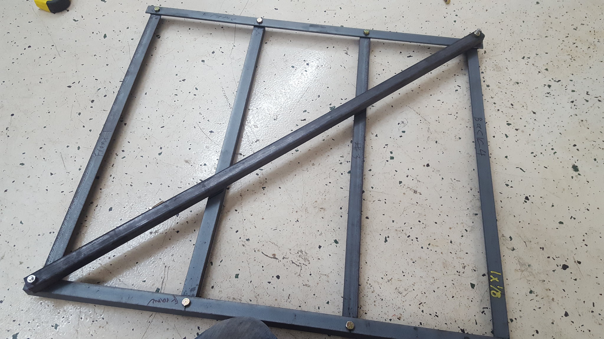
started my butterfly brace/trans mount. the long side pieces will be welded to the 2x2 rails that have yet to be put on. the bolts will all be welded into place, thereby creating studs. theres also another 1x1 tube that i need no fab in before all the welding and such happens. will weigh about 10-15 lbs when done, which is far heavier than id like. but it'll be bombproof. i think. suggestions/feedback on this thing? remember, im making it all up as i go along, and im sure no engineer.
 20171231_102006 by Michael Crawford, on Flickr
 20171231_120529 by Michael Crawford, on Flickr
 20171231_130418 by Michael Crawford, on Flickr
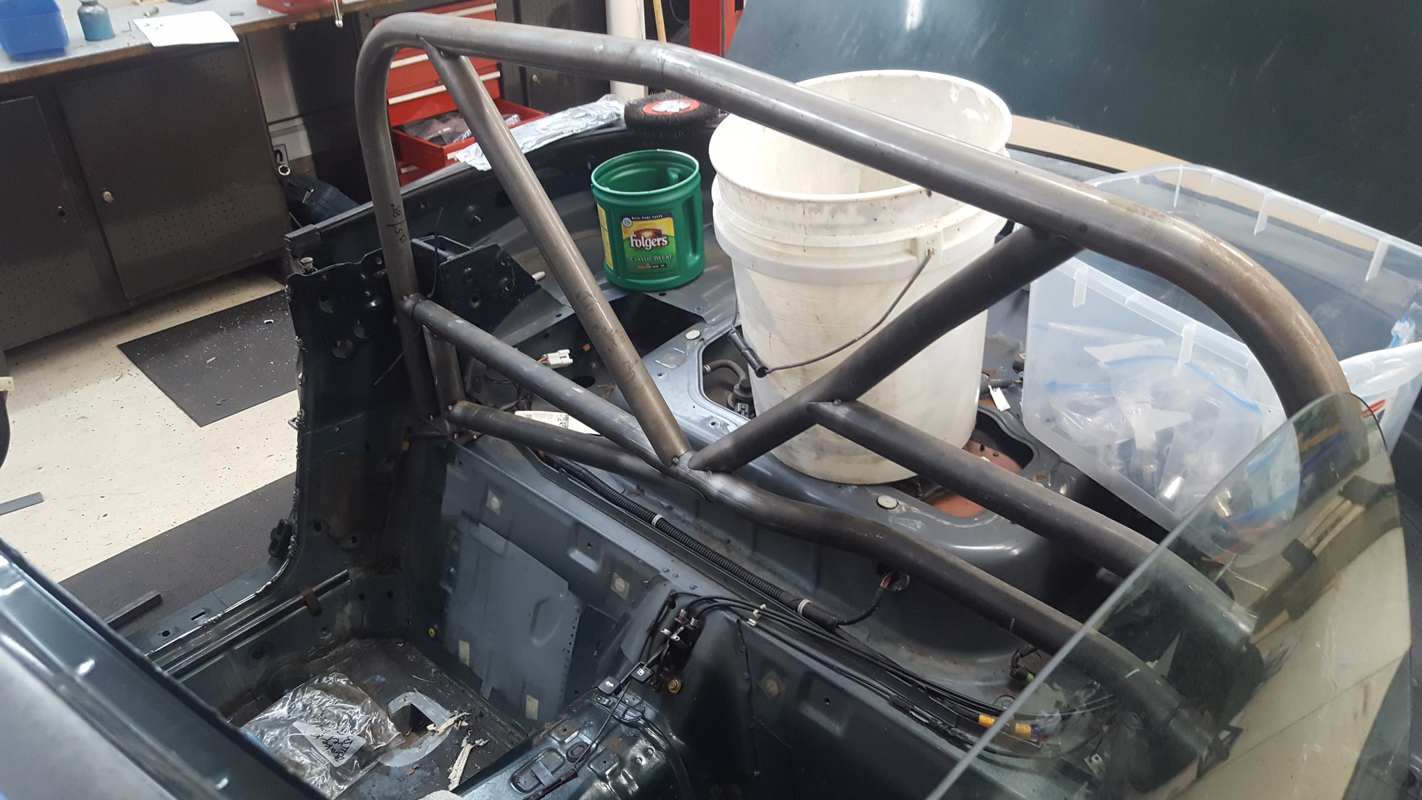
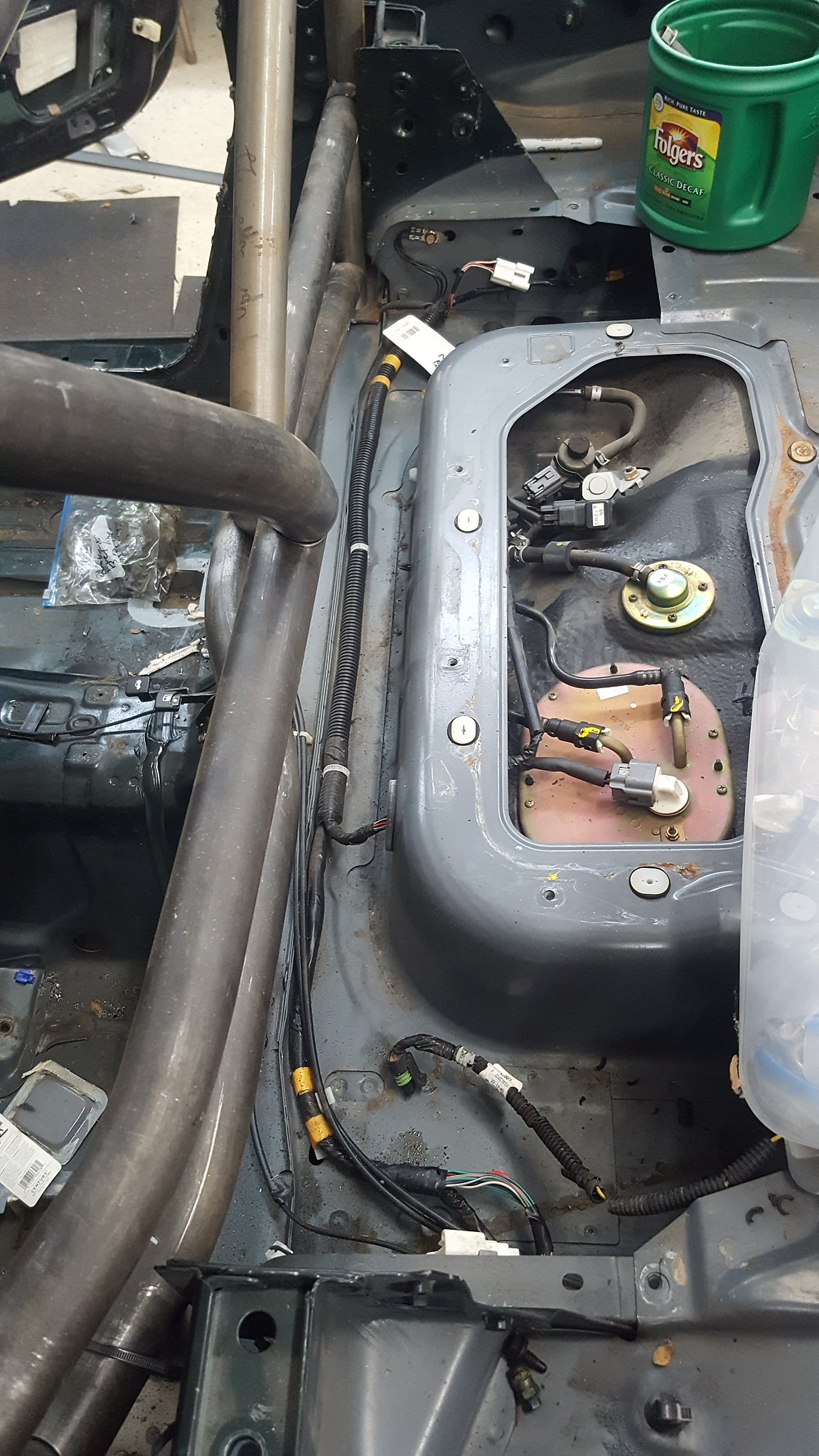
also, while i was working, i managed to knock over my entire pile of crap onto mu right foot. 3/8 plate, 1x1 tube. 1x1 angle, and a roll cage. 6 hours later my damn foot still hurts. so, to solve the problem, i cleaned the shop. part of this was finding a home for the roll bar segment. ZIP TIES!!!
 20171231_132007 by Michael Crawford, on Flickr
 20171231_132029 by Michael Crawford, on Flickr
will need to trim some flanges on the seat belt towers for it to sit where i want it. then, build my floor plates, rear downtubes, etc. but i LIKE this design. Its a whole lot better than the hard dog ace in my daily. however, i purchased the ace as it was the furthest from my head i could get and still have it pass the broomstick test with my unhelmeted noggin. the ace is in a daily. this is a race car that'll be driven to events. not to work....
lastly, started looking at hood clearance/upper intake mounting. to put the throttle body forward will require me cutting the timing cover for clearance, which wont leave me a place to mount an idler for the belt, or space it up 3/4 of an inch. this would make the intake poke through the hood considerably, and i think the throttle body as well. having the plenum through the hood could be visually awesome. throttle body, not so much. leaving it in the factory orientation may work, but that will require some more mockup and staring. the intake tube would be routed through the cowl where the wiper linkage lives, then out to the front of the car. or something. dunno yet. but im sure it will stick up above the hood now....
 20171231_133708 by Michael Crawford, on Flickr
 20171231_133714 by Michael Crawford, on Flickr
so...
a) the miata hood is aluminum... and tends to flex over 100mph
b) if you confine your hole to "not taking out" any of the ribs... you'll be fine. there's some discussion of this somewhere on Keith's Targa Miata build page.
re: intake
you might look at the "cowl intake" design that's floating around for miatas... fabbing some kind of twin snorkle intake that draws air from the "tub" between the hood gasket and the windshield that houses the wipers... might give you the flow/cool-air/space you need? You'll just need to put some thought into isolating the intake tract from the heat of the headers.
If i put the manifold in factory orientation, the throttle body will be IN the wiper cavity. Manifold is about 2 inches from the firewall at tb mount flange, tb is roughly 4 inches overall.
Cutting a hole would allow the entire rectangular intake pmenum to be about 1/2 inch above the bubble in the hood. This will definitely have some aero and flex effects that i have no idea how to research or anticipate.
1/2" seems like a small enough about that you might-could "persuade" the hood bigger. This thing's getting a respray, right? That, or you could try making a taller bubble with the "t-shirt fiberglass method"... should fare better than the flares did?
putting the throttle body into that cavity might make throttle linkage connection a pain. I can't recall how structural that piece is... ok to poke holes in it... not as sure about cutting a slot through the top of it.
you've already modified an aluminum oil pan. Maybe time to consider modifying the IM?
After looking at it more today, theres no way in hell that i can run a rear facing throttle body. It will wind up in the passengers compartment no matter how i do it.
So front facing it will have to be.
Hood scoop/reshape is a possibility, as well as custom plenum mods. Id rather not do either, but it is what it is.
If stage 3 didn't call for all the boost, id be considering itbs and megasquirt. And then it would be out of the challenge due to budget. But stacks sticking through the hood like an old can-am car would be badass.
The last update for a minute (or at least until next weekend or so)
finished up welding the butterfly brace today. The x looks crooked in pictures for some reason, but its not in reality. Also, my welds are ugly but have good penetration. That's why grinders and flap wheels exist.
 20180101_134301 by Michael Crawford, on Flickr
 20180101_140212 by Michael Crawford, on Flickr
 20180101_135314 by Michael Crawford, on Flickr
dad and I also spent some time grinding down the frame rails, and then cutting them out. Hes going to start fitting the 2x2 box while im at work this week. I was able to get a picture of us together while we were drilling holes for plug welds, which makes me happy. Please excuse my hair. Im just happy to still have it. (stocking cap while I was outside with a flap wheel in 10 degree weather)
 20180101_140411 by Michael Crawford, on Flickr
 20180101_134310 by Michael Crawford, on Flickr
 20180101_140914 by Michael Crawford, on Flickr
and the end result of framerail murder.
 20180101_152101 by Michael Crawford, on Flickr
[s] as a mechanical engineer, relook at that butterfly brace. A triangle is strong (i.e. your x which is 4 triangles). The intermediary braces add more weight than stiffness... If anything, something coming across the center of the x like a plus that makes the x into 8 smaller triangles which are stronger.
(the pentagons in the middle are not stiff, so you added some smaller triangles doing what you did but a plus over an X should be stronger for loads in the plane of the frame).
[/s]
Edit: my Structural Engineer of a wife tells me that what you did is stiffer because when a leg of the X goes into compression it'll try bow. So the 2 horizontal braces stop that bowing increasing stiffness. Adding the + would not increase stiffness as the top left to center would still be the same length and still flex the same amount. She does add that keeping the angle iron intact by flipping it if you can give up the ground clearance is technically stronger even though you welded it to the tube steel.
Hmm.....
So, what im understanding you to say with the edit is that the twisting motion, which this brace is to counteract, should be well controlled with my design, but would be technically stronger by adding a piece through the center of the x thereby making more and smller triangles. However, this wouldn't combat the twisting motion. Flipping the angle iron 90 degrees so the flats were above the plane of the box tubing woul combat twisting motion more though.
Am i reading this right?
You'll need to log in to post.