
Ian F
UltimaDork
11/12/13 8:05 p.m.
Yes, the "realists" and the "dreamers". Fortunately, there are enough bull-headed dreamers to forge ahead regardless of what we realists say, otherwise we'd still be rubbing sticks together and living in caves...
Anyway, my plan is more one of pragmatism: I simply want the car back together and on the road as quickly and cheaply as possible. I have more than enough welding, wrenching and wiring ahead of me just to put it back together that I don't need to be mucking about with trying to re-engineer most of the car as well. Plus, I have enough experience behind the wheel of an 1800ES to be happy with most of what Volvo designed in the first place... If all goes well, I would like to have the car come in at under $10K with maybe half of that in the B20.
And on that note... it's time to go downstairs and organize Volvo parts...

NOHOME
Dork
11/16/13 6:40 a.m.
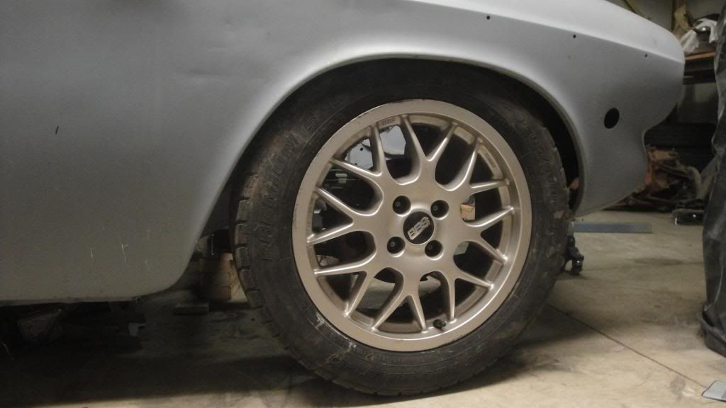 Looks like its gonna fit. Just barely!
Tossed some junk 205-55 16 tires on the rims and attached the lower a-arms to the frame where they are going to reside. A-arms are parallel to the ground plane. Squared the wheels with zero camber. (no upper a-arm yet)
Set the ride height measured at the pinch weld to 7".
Might have to join the Hellaflush crowd.

Ian F
UltimaDork
11/16/13 6:39 p.m.
Oh yeah... I think those BBS wheels might actually be for a Volvo. There's a used car lot I pass going to/from work with an older S40 with those exact wheels. I remember the 4x bolts pattern striking me as odd for a Volvo, but then again I remember that platform was shared with other Ford/Mazda cars of the era.

Josh
SuperDork
11/17/13 7:16 a.m.
Older S40s are not a Ford/Mazda platform, they are based on the Mitsubishi Carisma. Newer ones are the Ford C1 (Focus/Mazda3) platform.

Ian F
UltimaDork
11/17/13 7:54 a.m.
In reply to Josh:
Ah... right... I always forget that.

NOHOME
Dork
12/4/13 11:03 a.m.
Still at this.
Good news is that I can leave the factory frame-rails alone. Still at a bolt-in stage.
By stealing the idea from the Miata V8 sub-frame with the mounts located below, rather than besides the rails, I move the pick-up point support right under the Volvo factory rails. Could not be better located.
So, by virtue of some clever origami and a water jet, I can make the lower a-arm mounts and adapter to the Volvo frame-rail out of a single folded piece of 1/8" plate.
Drawing does not look like much progress, but a lot of tape measure time and internet searching has gone into this.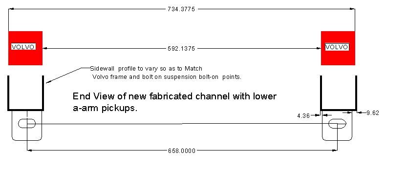

NOHOME
Dork
12/4/13 12:51 p.m.
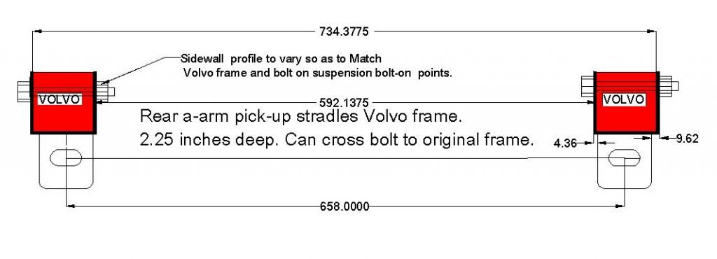
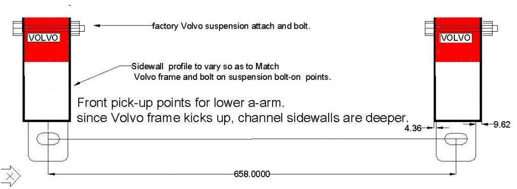
Here is a better view of how the new channel will relate to the existing frame rails.
First image is of the rear mount. The side-walls will be just over 2" when they hit the top of the frame-rail. A bolt will need to be introduced through the frame with a tube welded in to re-enforce.
The second image shows how the sidewall needs to rise to meet the frame kick-up. Going to end up with around 5" of side-wall and I am a bit concerned about the unsupported nature of the structure. Might have to do some work there. Only welding to get this far will be the piece of tube to re-enforce the rear mount point where the bolt goes through the frame.

NOHOME
UltraDork
12/6/13 8:54 a.m.
clean parts always make me happy.
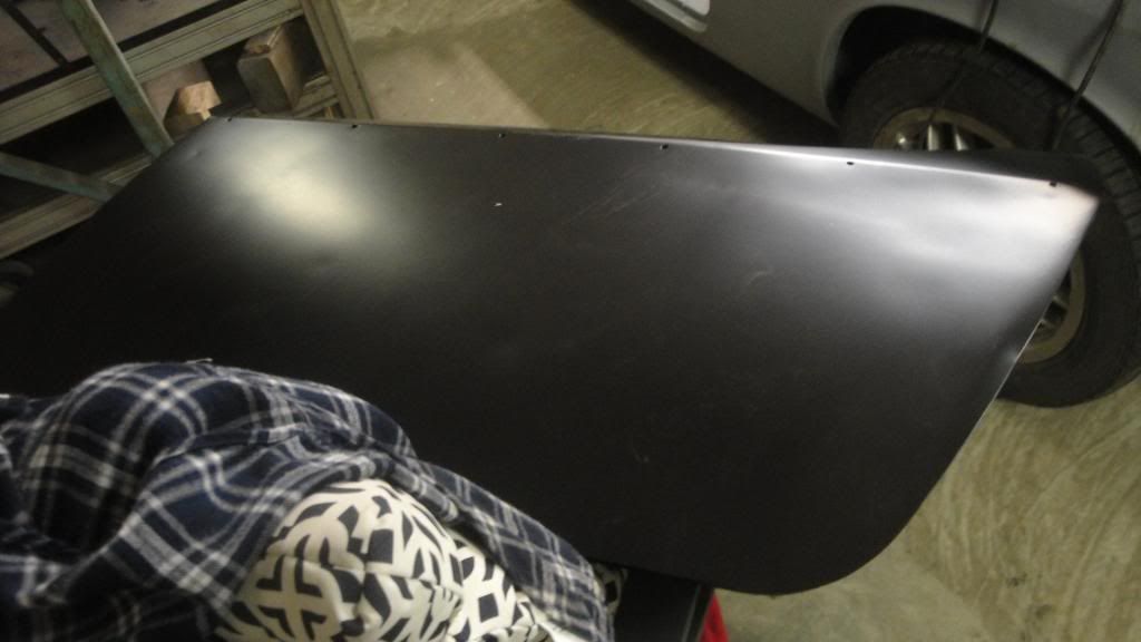
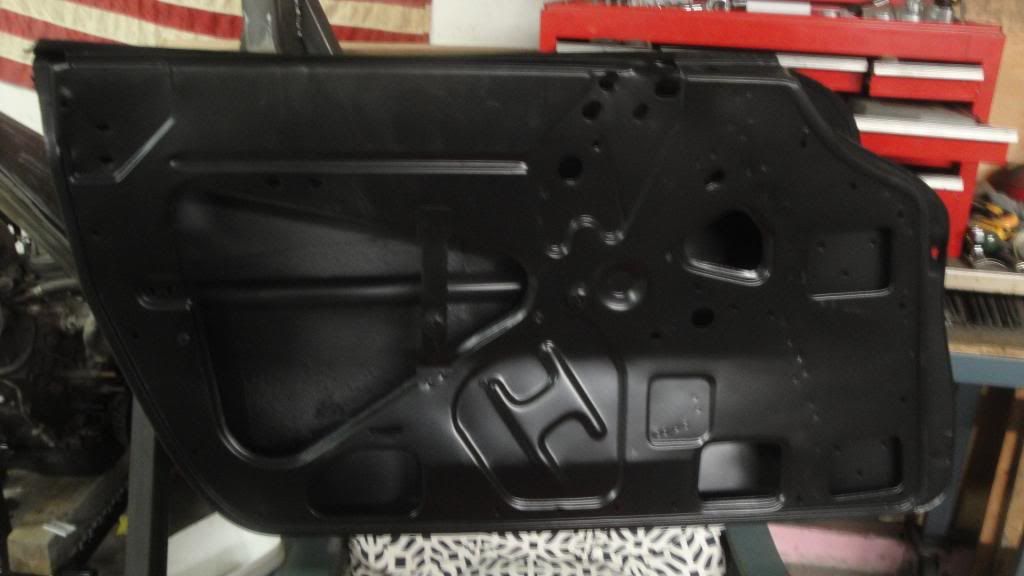
When I bought the car, the whole shell had been sandblasted and epoxy primed.

Great!
Except the doors and roof panel were not coated. And left for a few years.
E36 M3...that meant that they came in a nice uniform coat of orange surface rust.
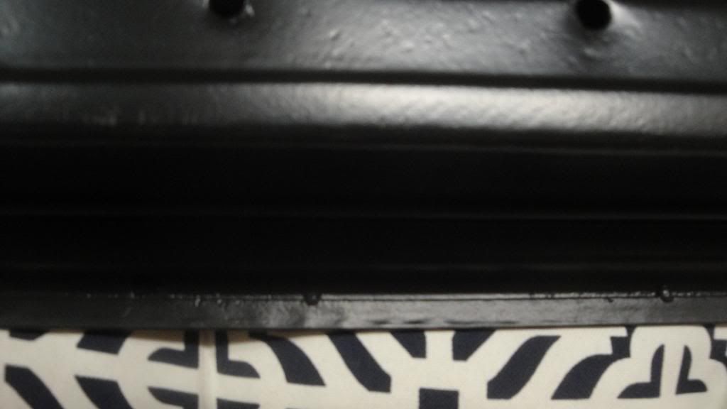
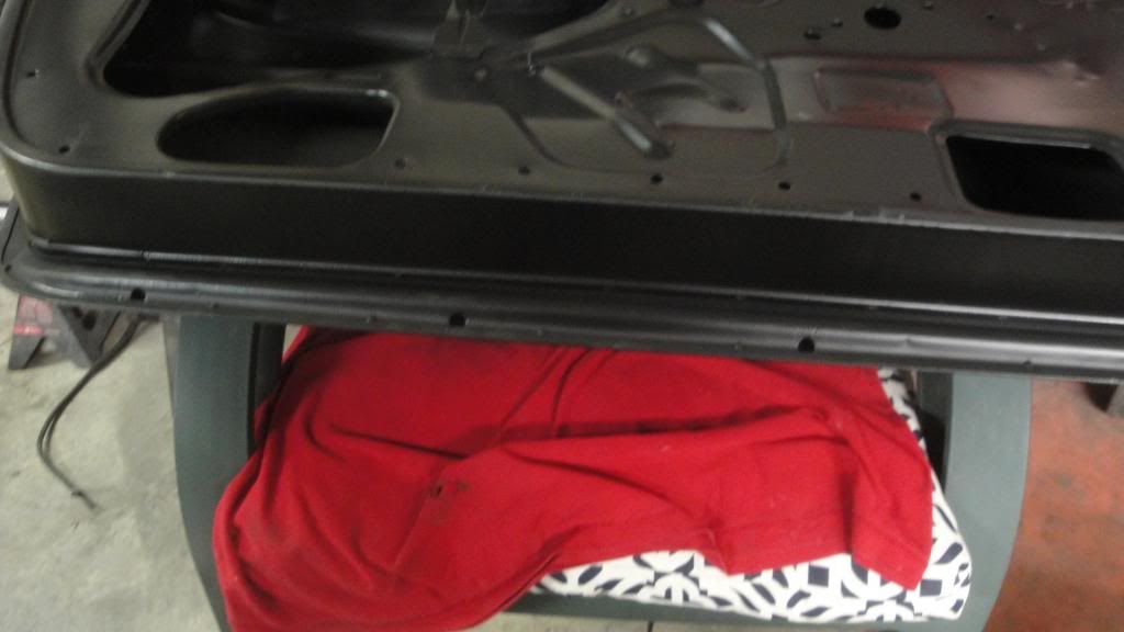
So, off to the blasters go the doors. The place did a very nice job...even removing all the mechanisms and glass beading those separately.
No rust in the bottom seams! I love working with clean tin
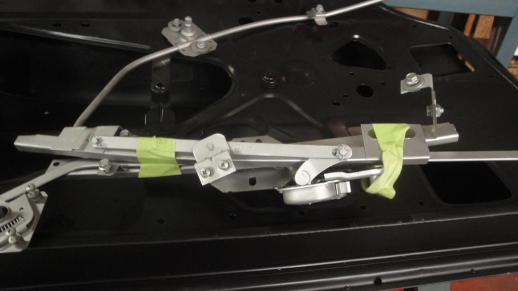
Tunna...
I have learned the lesson that you are in the midst of learning "Rusty Cars Suck!"
yeah, clean is an understatement...

Ian F
UltimaDork
12/6/13 10:26 a.m.
When we reburshed the ex-g/f's ES front suspension, we had just about all of the parts professionally blasted. She was stunned at how clean they were when they came back. Well worth the added cost vs. DIY cleaning.
Since then, I've aquired my own blasting cabinet, although I haven't tryed it out yet.

NOHOME
Dork
12/25/13 9:04 a.m.
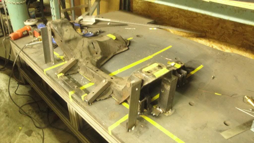 Since in my mind I have a plan of action that I think will work, I went ahead and built a jig to pick-up the Miata suspension and rack mounting points.
The jig will allow me to fabricate a subframe that will then graft on to the existing Volvo frame.
Having a square and flat 1" steel plate to lay this out on is a big bonus.

More progress being made. I am nearing the end of what I consider to to be the "Proof of Concept Stage" of the project. This means that I am pretty convinced that all the technical hurdles can be overcome, I have a pretty good idea of where all the parts are going to land and that I have a few workable plans to put into play with backups if need be.
The front is going to use the original Volvo frame members as a foundation. These suckers are solid. I built a U-shaped channel that tightly straddles the frame and will mount the rear a-arm mount under this channel. The rear a-arm pivot will be welded to the bottom of this. It is just held up in place for this picture.
The channel shown in the picture will be replaced by a longer and taller version that will pick up the stock Volvo crossmember mounts that you can see in the original frame. I will make a similar mounting point towards the rear of the channel just to lock down the rear a-arm pivot with a bolt through the frame rail. The hole will have a reinforcement tube that keeps the frame from collapsing.
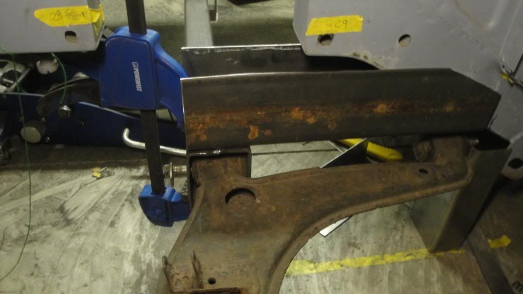
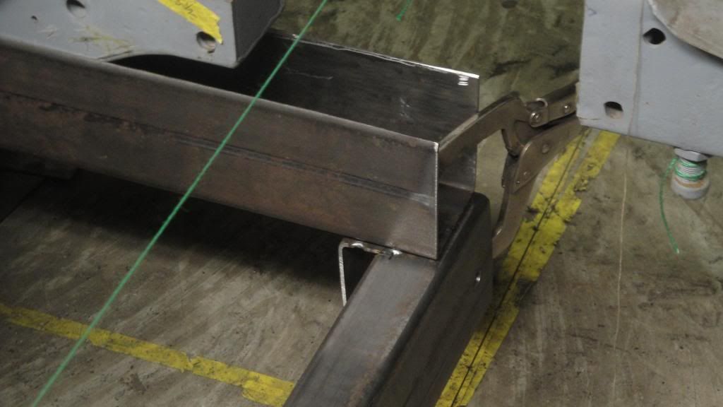
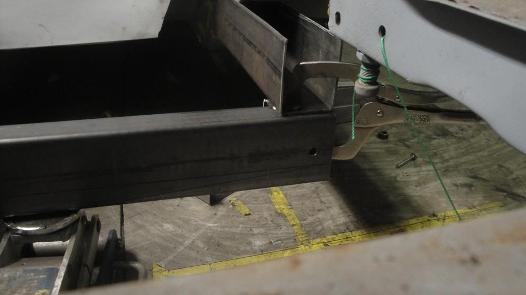
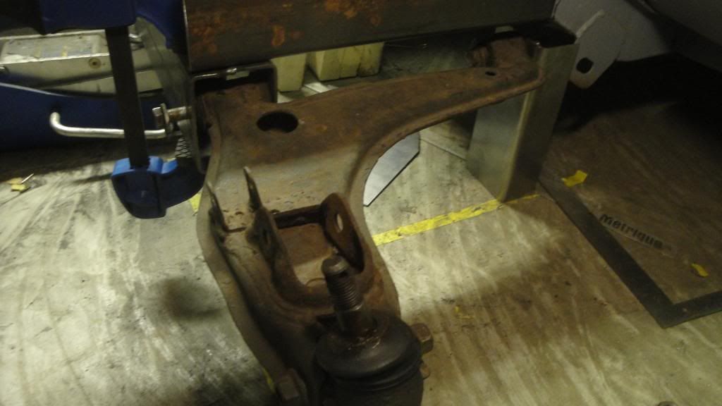
by some stroke of luck, the upper a-arm mounting tube wants to be just alongside the channel; it will be easy to fab a mount that mounts it to the side of the channel. Some clearancing of the Volvo frame will be required to clear the larger diameter A-arm pivot points.
The front a-arm pivot is built directly into the crossmember. The crossmember is a 2x4 by .125" with the ends widened from 2" to 3.125 to form a receiver for the front lower a-arm. Still have a full 6" of ground clearance under the crossmember that might come in handy if I need to drop the engine down and carve into this area.
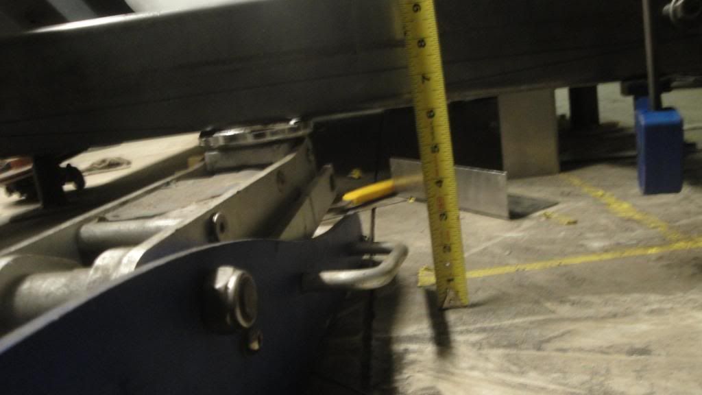
The rear cradle is (loosely) in place with the wheels attached. I got lucky for a change as the Miata subframe measures out at 796mm wide and the Volvo frame rails are 800mm apart at the inside. The cradle fits like a glove between the rails and there are no Volvo based obstacles to the movement of the suspension arms. The frame needs to move up 2.75" from where it is in the pictures and that will require some metal removal. Rear seats might not be functional (not that they ever really were!).
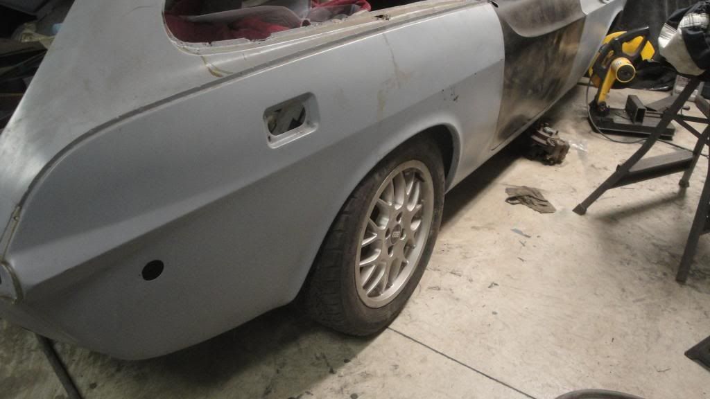
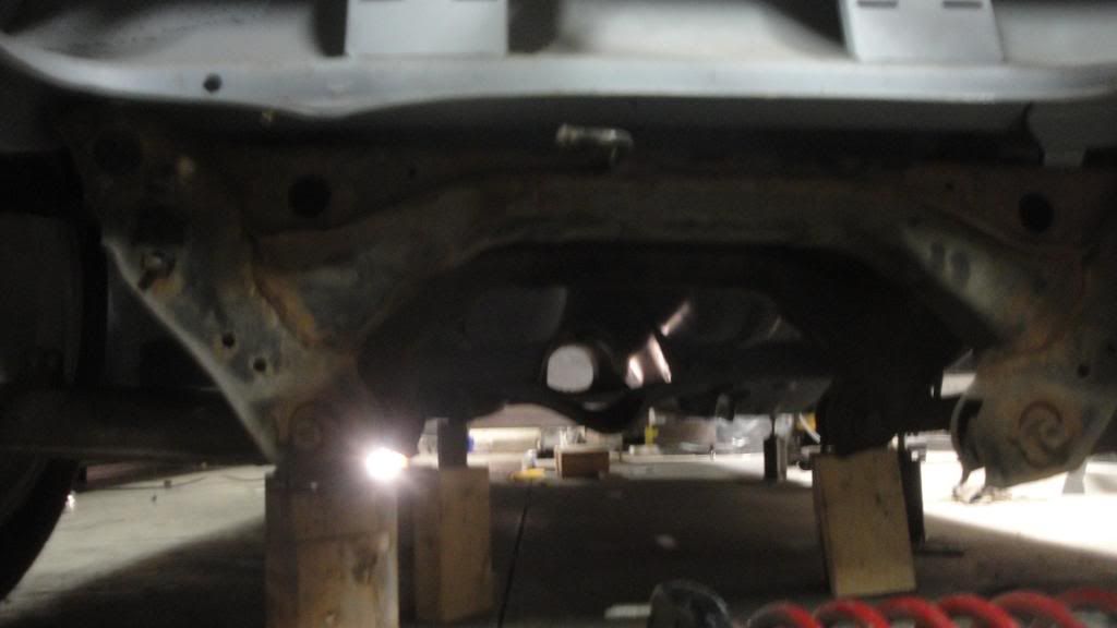
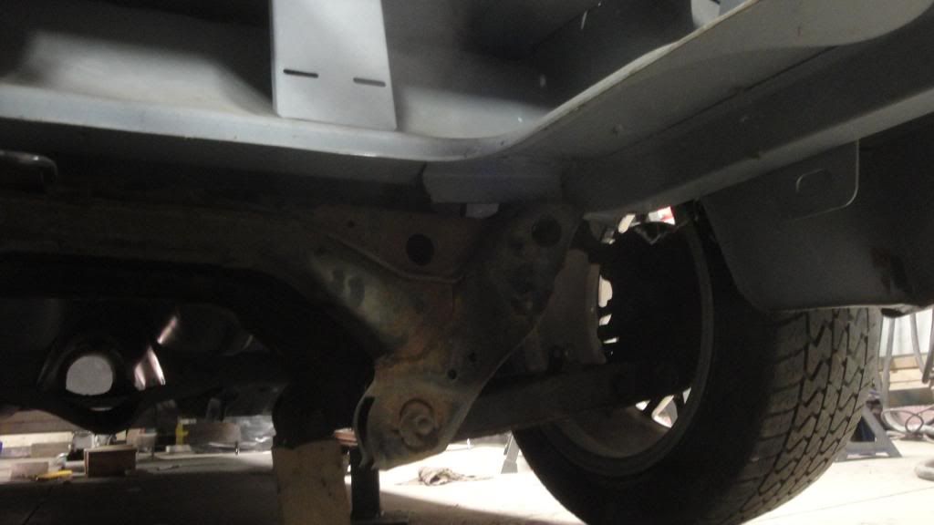
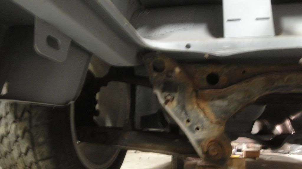
The rear tires are snug to the body and will require some form of clearancing. 1/2" would do it pretty much, so I might look into wheels with different offset even though I really like these. (and they are paid for) I think these are 43 mm offset. The fronts are pretty much the same as far as needing a tad more room.
The next stage is to finish the design for the front shock mounts. It would be useful if I can lay my hands on some salvage parts from a Miata shell and integrate those into the design.
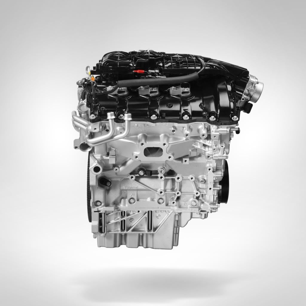
Forgot to mention that the project almost took a major change of direction when I found a 2012 LFX 3.6 engine out of a Cadillac. The deal breaker is the height: at 30" tall, it is not going to fit under the bonnet without a significant scoop. The 302 will have to suffice.
cant wait to see this when its done, Pete
You ever have one of those days?
While the jig that I built would have done great if I were building a traditional Miata V8 subframe, it had enough issues with the new configuation that I had to tear it down to the talbe and start again.
Thankfully, I had not cut the upper a-arm support tube out of the original k-member yet.
After a long day, I am almost where I was this morning!
yes, yes i have.
with the plymouth i cut the frame rails to my original length needed to work with the parts i had. then i got new parts, that required me to need 8" longer rails. the only thing that saved me was that my front suspension points were still on the too short rails, so i could add front instead of buying a whole new piece of tube.
looks awesome. the rear subframe reminds me when i was RWD'ing my FWD grand prix. one from an mn12 t-bird fit like a glove.
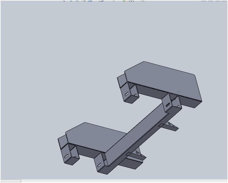
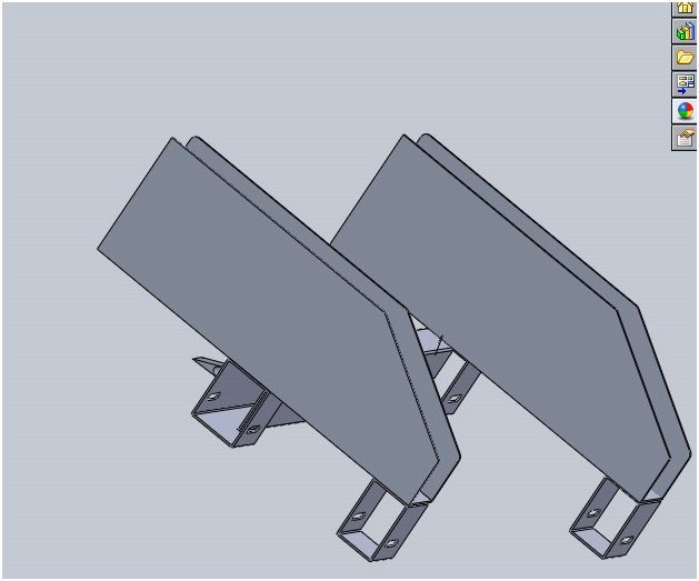
Sketch of what the new K member is going to look like as far as installation and lower-a-arm pivot points. Gussets will be added as needed once I get this on the car and see what nuances are required to clear any exhaust routing and steering components.
The saddle slips over the existing frame rails which Volvo was nice enough to make straight and symmetrical at 2.81" wide.
Fabrication so far should be simple enough.The K member will be built on the frame jig for alignment and geometry assurance, and the new part will bolt on to the Volvo using the factory cros-member attachment points plus one new one.
I have been debating if it might be a good idea to use a helping of panel adhesive on this assembly? Might add strength without the side effects of welding.

Ian F
UltimaDork
1/15/14 9:17 a.m.
Question: where are the upper shock/spring mounts going?

NOHOME
Dork
1/15/14 12:29 p.m.
Ian F wrote:
Question: where are the upper shock/spring mounts going?
Actually won't be too bad. The upper a-arm pivot sits pretty much flush against the outside of the saddle. Have not decided on how I want to attach other than a big ugly weld bead, so not there yet.May want to integrate some camber adjustment into this while I am there.
The shock spring mount must tie back to this structure while at the same time picking up some support from the inverted "U" cut out where the original crossmember fit. I wont finalize the shock mount until I have an upper and lower control alrm in place and can cycle the suspension through a full cycle to make sure the location is good. Already know there is plenty of room for the shock assembly. If I do end up finding some Miata shock mounts, I will scavenge what I canand graft the mount in for a more factory looking finish.
Unfortunately Ian, this will not be a cut free installation as I will need to clearance some Volvo frame where the A-arms attach; their diameter wants to go inside of the saddle.The photograph gives you an idea ow what needs to be trimmed to accomodate the a-arm pivot.
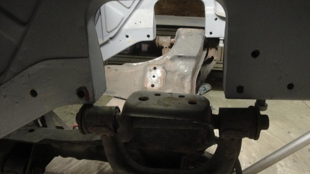
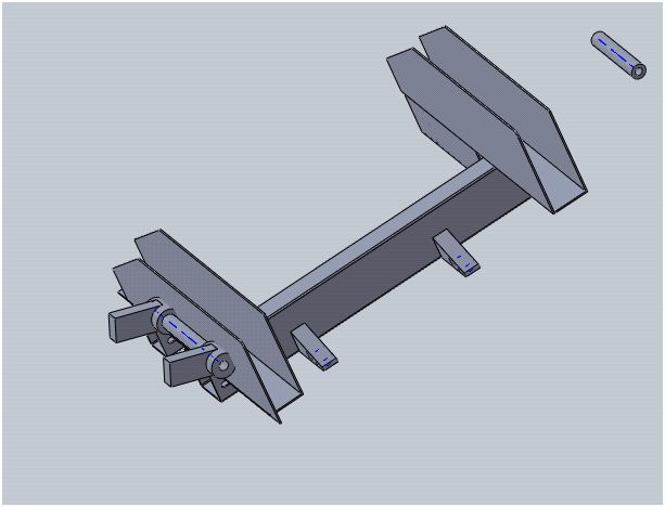
I am cutting up a ton of steel trying to make this look elegant as well as functional. Solid-works is good for some of this, but for my limited imagination, no substitute for physical conceptual mock-ups .

Ian F
UltimaDork
1/15/14 12:35 p.m.
To be honest, what you're going through seems like a lot more work than simply chopping everything out and grafting in the structure and mounting points from a Miata...
Ian:
If the final result were to be using a Miata drive-train, I would agree.
However, if I installed the Miata structure and original K member, once I was done, I would only be at the starting point of a Miata guy doing a 302 swap. That means that I would have to build a K member for the 302!
The K member I am building should give lots of room for headers and starters. The Monster Miatae are somewhat restricted in those areas. Airflow around the engine is also optimized with this method. I hope!
Is this a lot of work? Yeah it sure is, would not have it any other way. I could be halfway to paint if I had chosen to just restore the old girl.

Ian F
UltimaDork
1/15/14 3:14 p.m.
I guess I look for the easy-button as much as possible. I'd rather be driving than building. I don't really enjoy the "build/wrenching process" like so many here do. Just a means to an end (driving!) as far as I'm concerned.
It's funny to me as everything you're doing I've already done in my head. Get ready for a few more set-backs... 


 Looks like its gonna fit. Just barely!


 Since in my mind I have a plan of action that I think will work, I went ahead and built a jig to pick-up the Miata suspension and rack mounting points.


