I did this last fall, but had yet to actually sit down and write about it. But recently someone had a few questions about it and my answers constitute most of a post anyways. So here goes.
Last summer I came to the conclusion that speed-density based tuning just wasn't for me. A lot of people seem happy with it but I could never really get it to adapt to changing variables properly. I would tune it in the summer and it would be great, then fall would come and even at the same coolant and intake air temps the car would be lean. Or it would always stumble a bit on a hot-restart, and after-start enrichment was unable to tune it out. Or the required warmup enrichment curve would vary a bit and I would have to run the car extra-rich as a precaution during warmup. I was relying on the closed-loop system to get the idle to smooth out in that sort of situation. That's never a good sign. I'll explain some of the tuning process as well so people can see how the MAF assists with this.
With that knowledge I started to look at my MAF options. There are a ton of them out there but I decided on the MAF from a Z32 300ZX. This was for two reasons: The flow curve is known and available online, the outlet is the same size as the stock intake tubing, and the inlet looked suspiciously like the stock Rx7 flange. Turns out none of these panned out the way I wanted, so I'll make it short and say that you are probably better off with an R35 MAF in a custom housing. I'll explain more about that later on.
Stock Rx7 MAFs were not an option for me. S4 has the flapper door style which adds restriction (probably not a ton, but enough that I noticed when I removed my old one) and S5 is marginally better with the sliding cone but still not as good as a hot-wire style MAF.
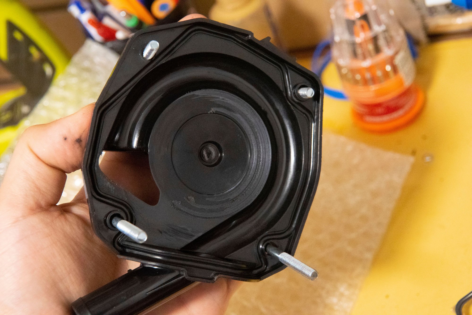
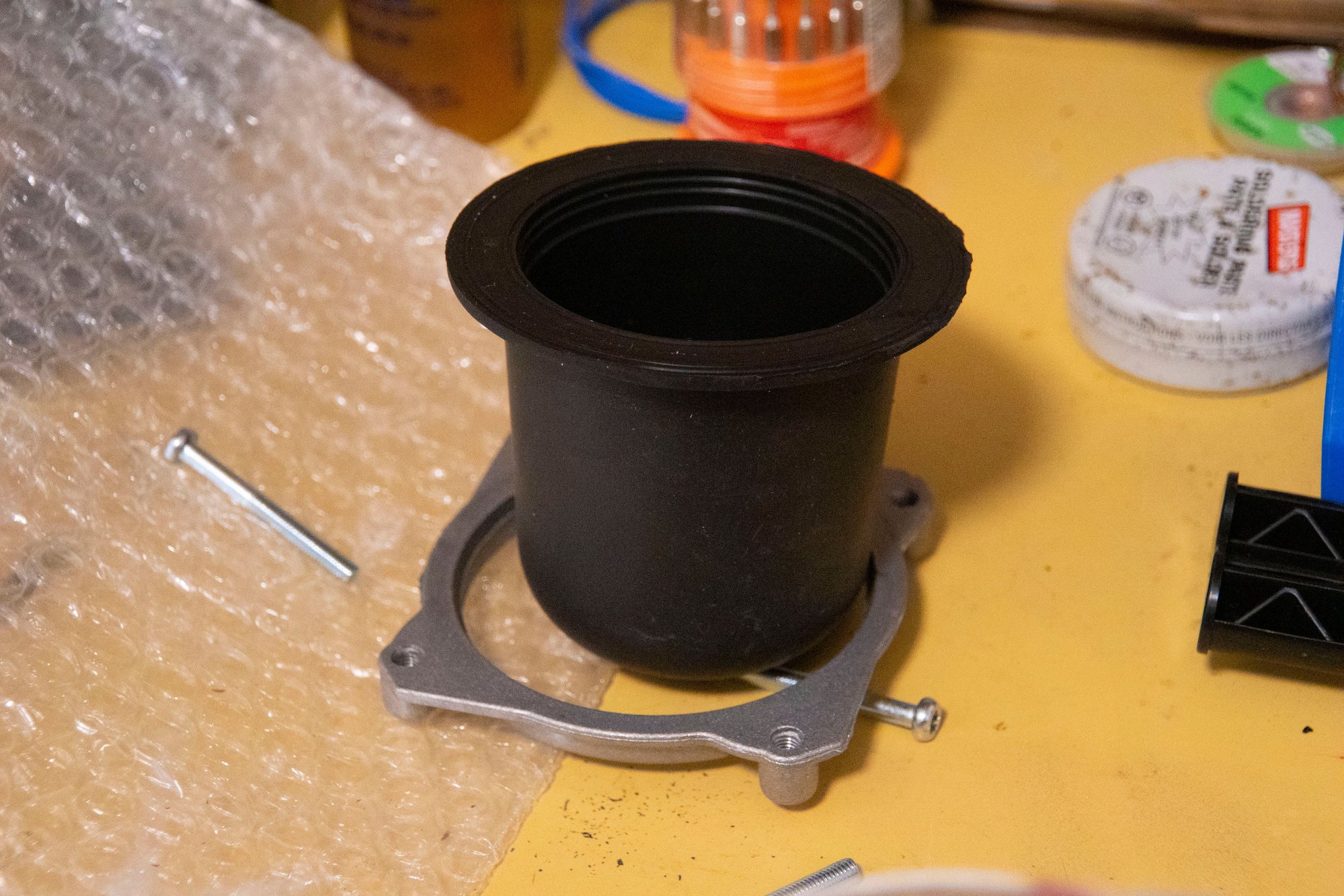
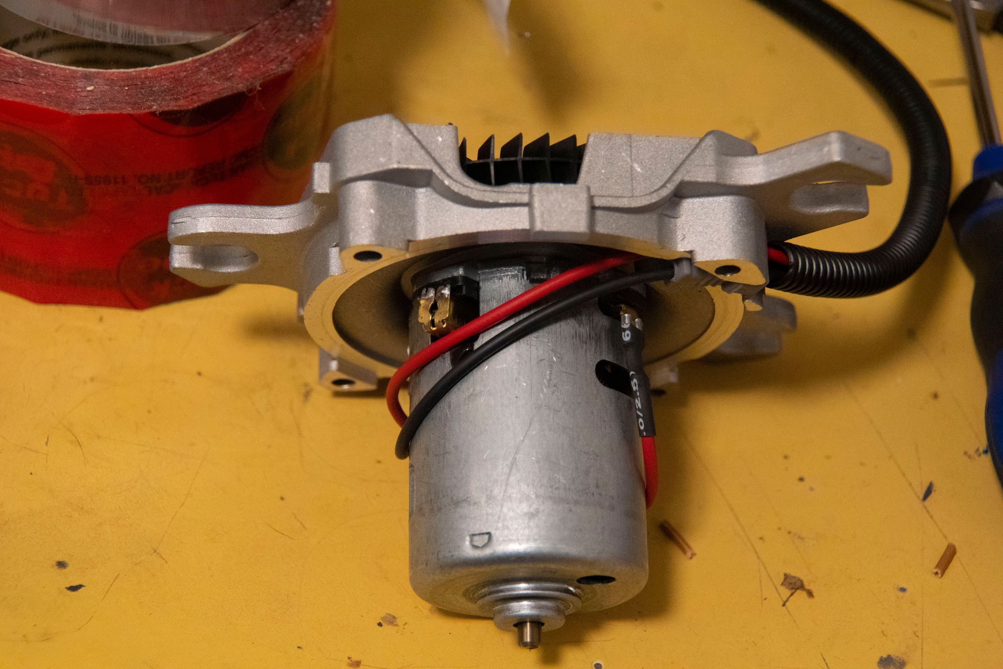
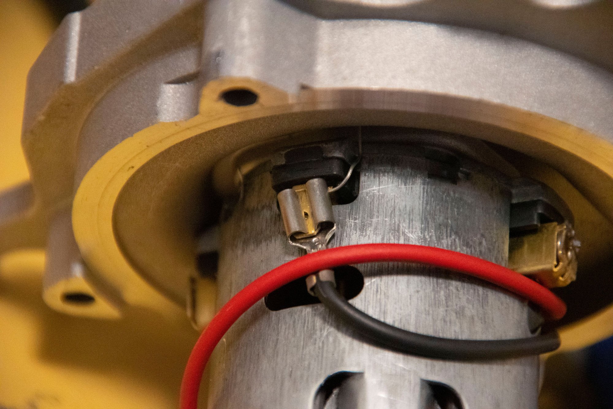
I ordered a used OEM Z32 MAF on eBay (don't buy the knockoff ones that are of dubious quality):
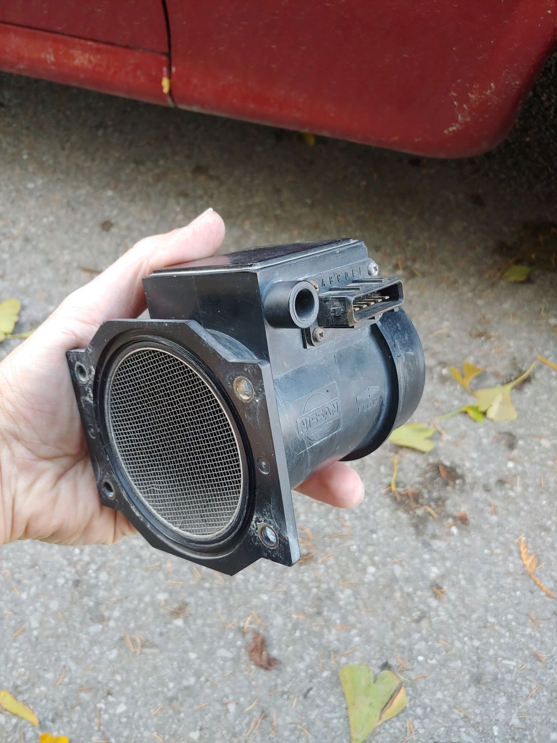
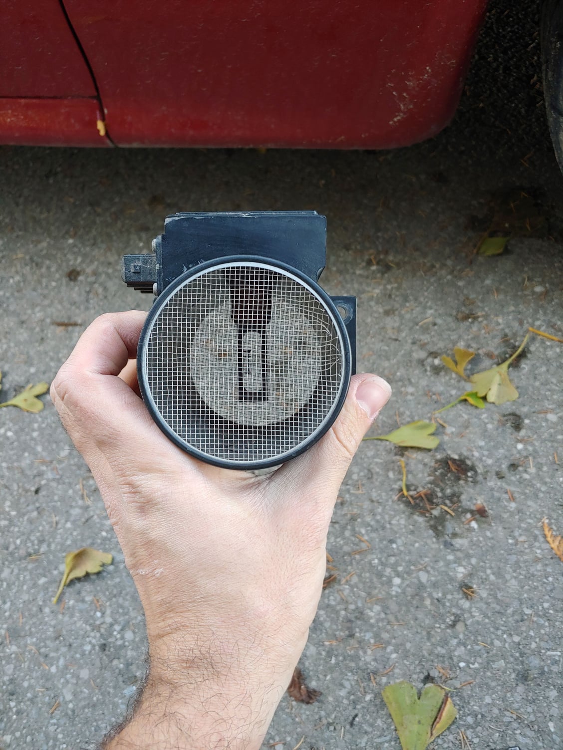
The mesh is a little wonky, but that doesn't really matter. You can see the hot wire in the center in that little plastic housing. However, I did notice a couple of things. The first was that the bolt pattern didn't match up at all with the stock airbox, and the second was that even if it did the MAF would be too short to reach the intake tubing. This meant an adapter would be required:
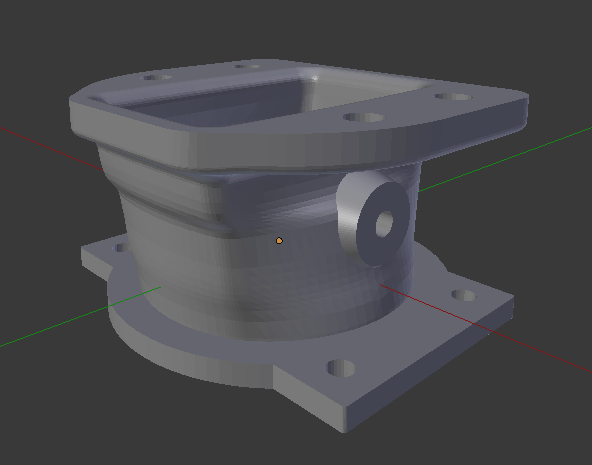
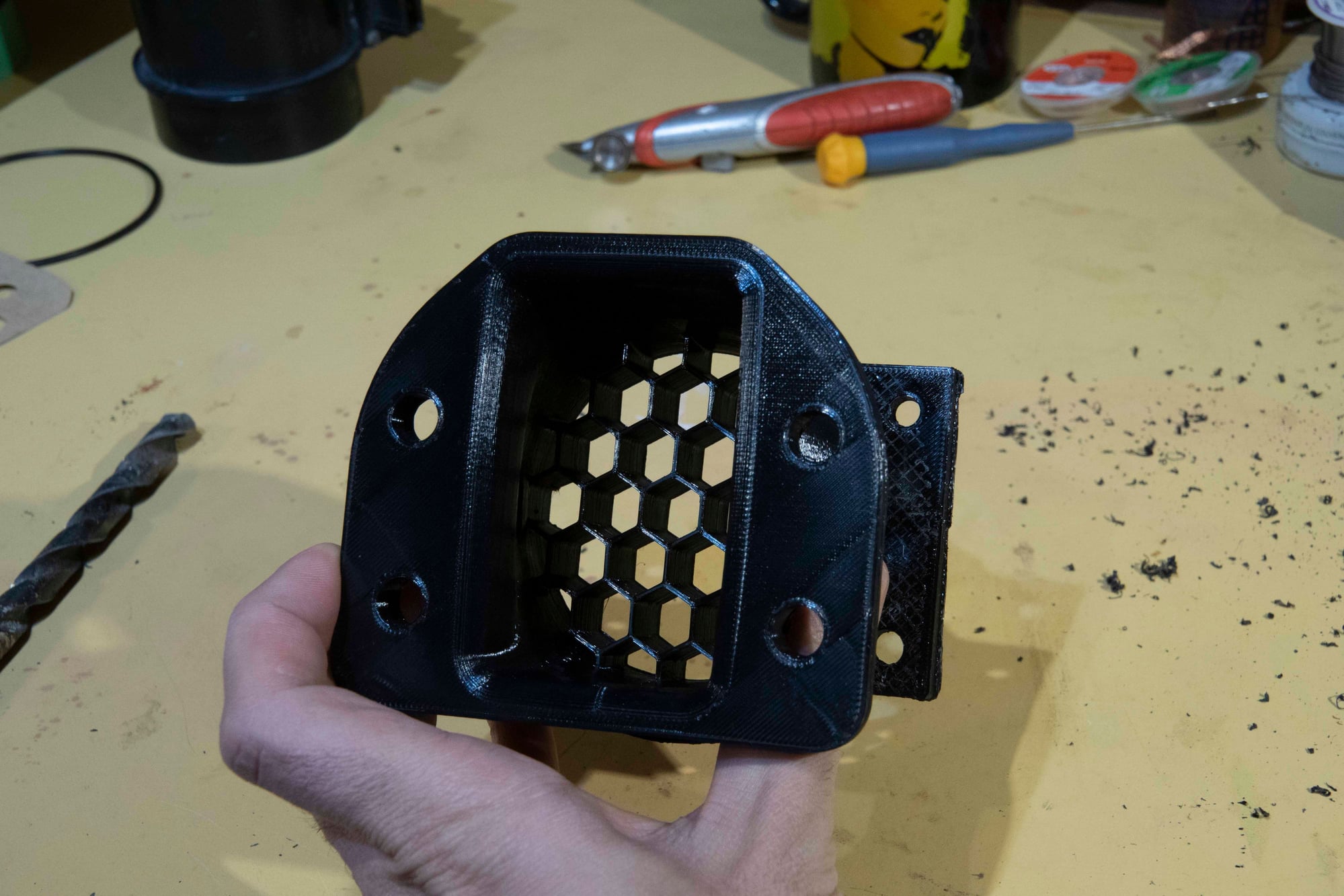
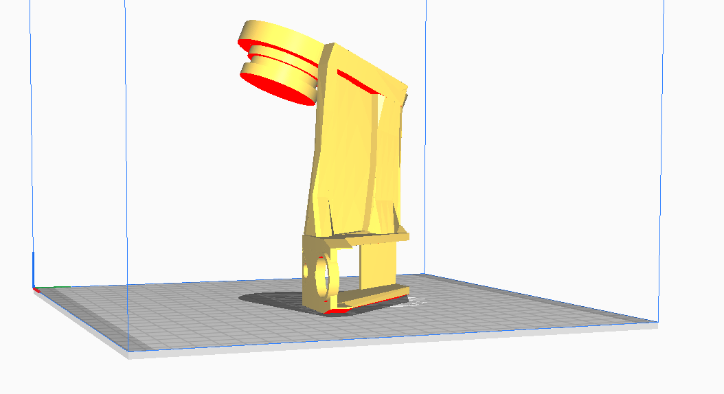
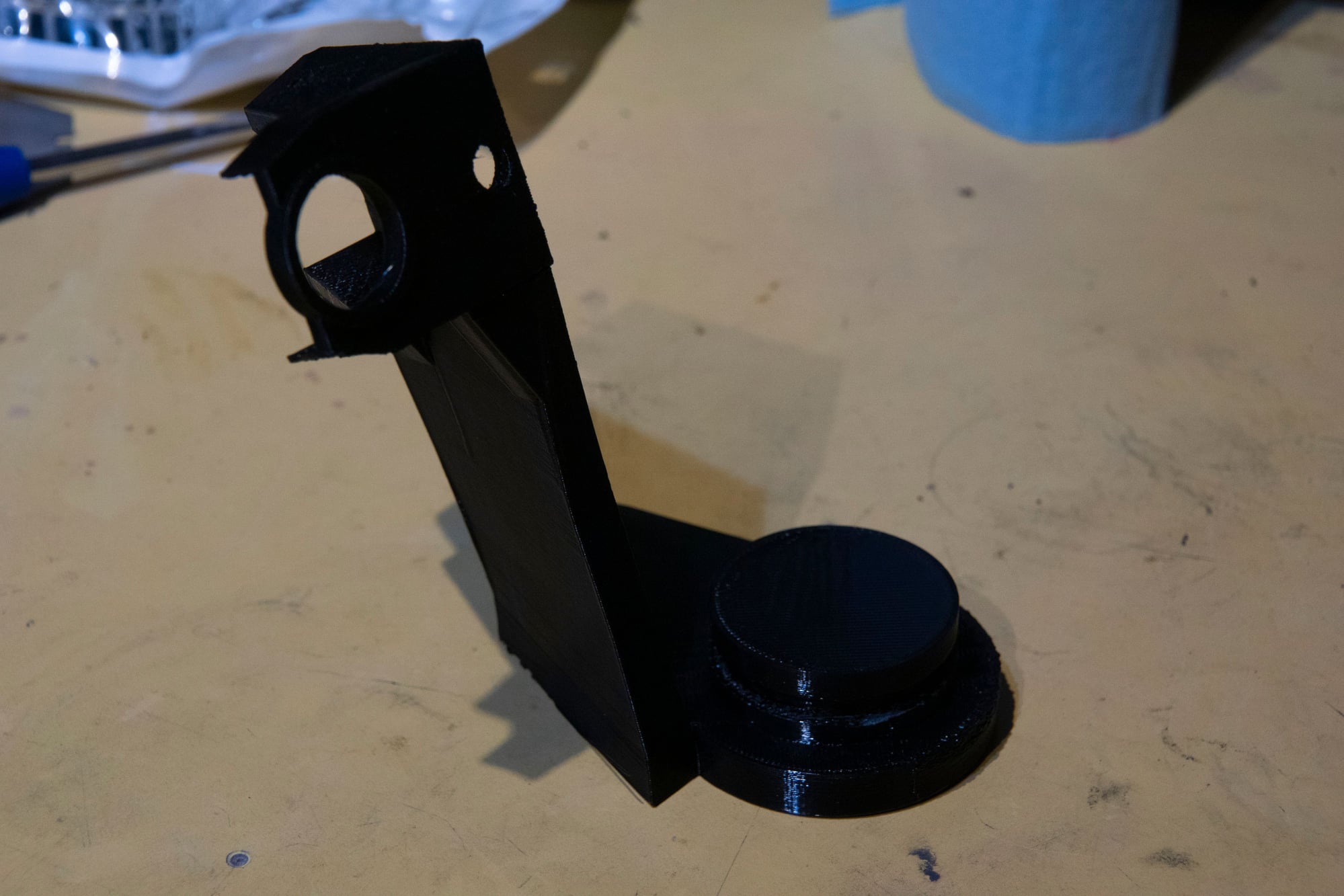
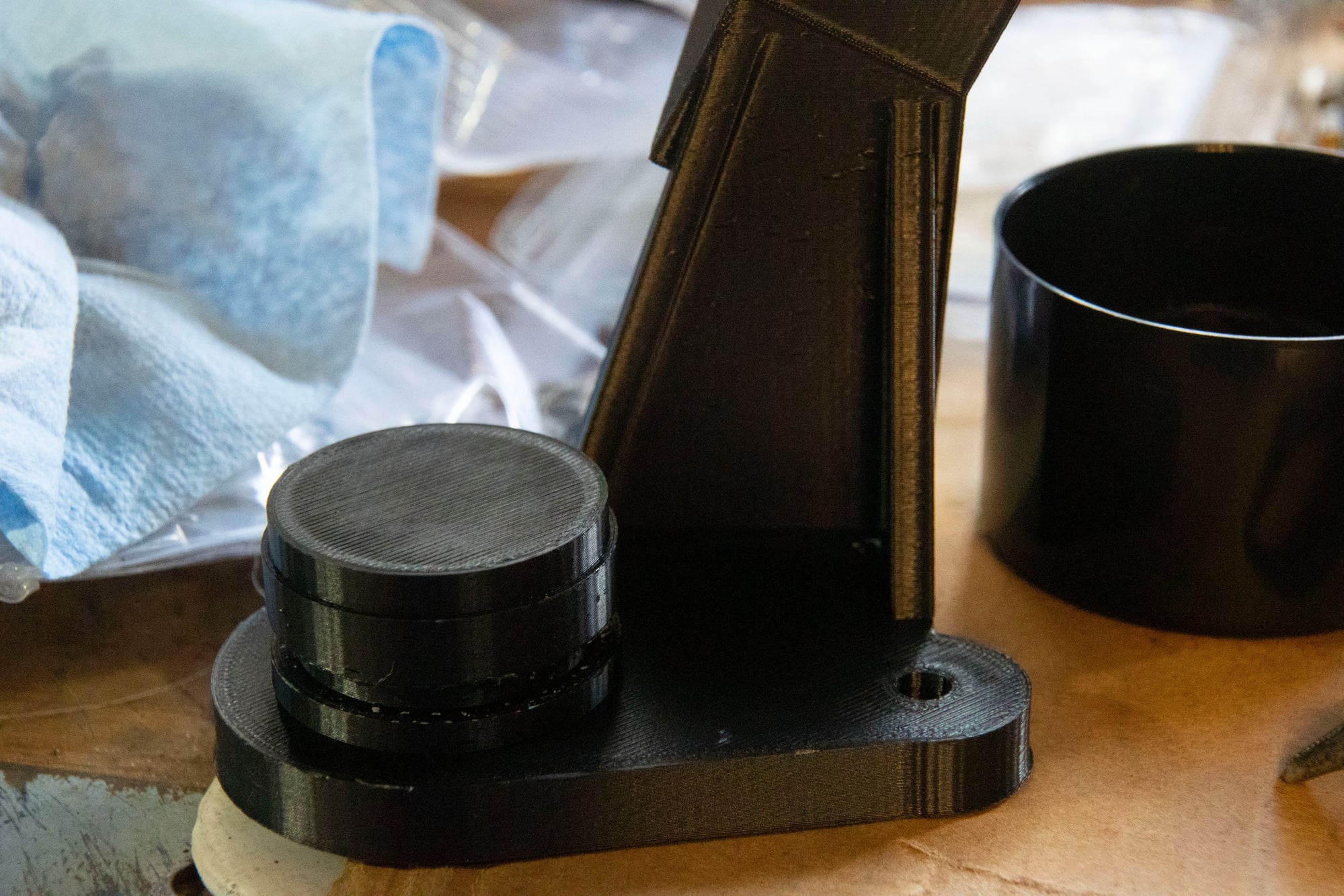
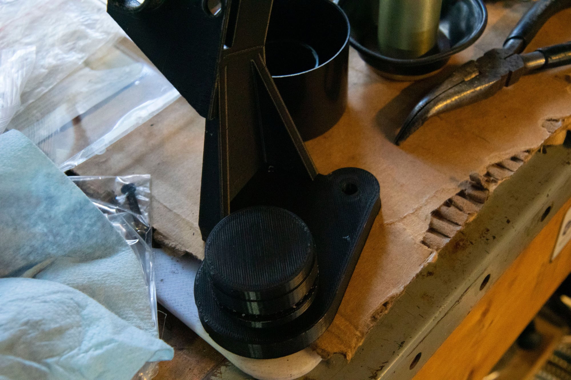
The one side is adapted from an existing model on Thingiverse that I had been using to replace the MAF with a tube. The other side has the bolt-pattern necessary to adapt to the Z32 inlet flange. There's also a small mounting boss for my IAT sensor, since I find putting it here is more accurate than the manifolds due to heat-soak.
If you're wondering what's up with the honeycomb shape, that's a simple air-straightener I made. One thing I learned in the early testing stages was that airflow is super important with this style of MAF. The air should be in a straight tube the same diameter as the MAF for several inches before reaching the wire to ensure consistent even flow throughout the tube. If the airflow is swirling around, all one one side of the tube, or reverting back in the tube, these will cause the MAF to be way out of whack. The honeycomb shape was an attempt on my part to mitigate the challenge presented by the shape of the intake in this area. Take a look at what I mean:
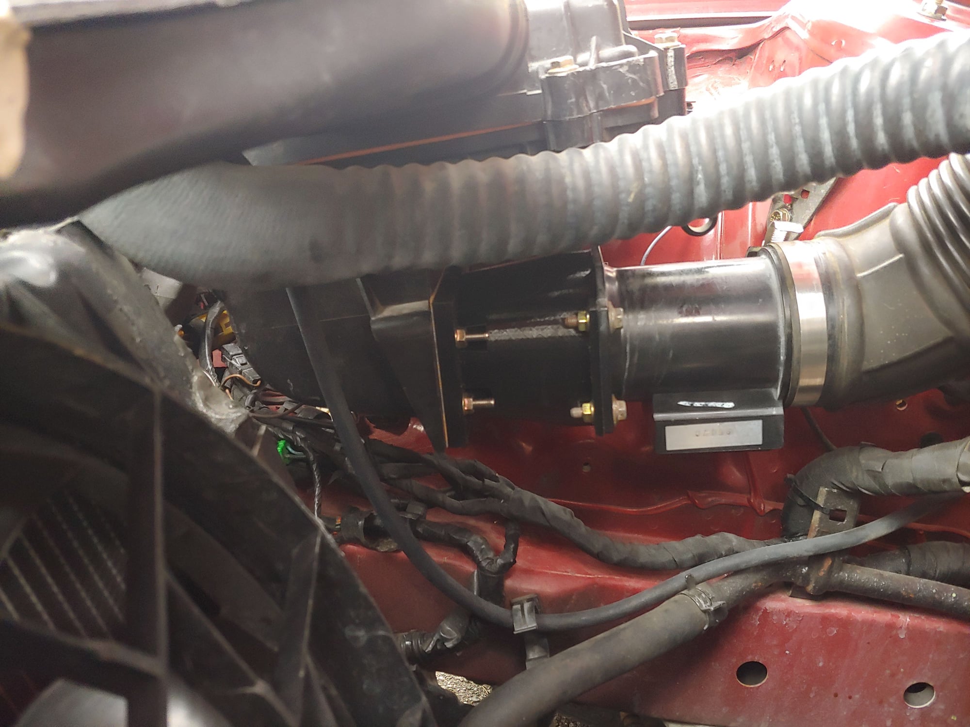
That's actually an earlier revision of the adapter (and it required the MAF to be upside down), but it still illustrates my next point. The air in the airbox passes through the filter, then makes a sharp 90-degree turn through the outlet. Then it has about 7-8" of space to straighten out before reaching the MAF. This is obviously less than ideal in terms of ensuring even flow. Hence why the honeycomb was a necessary addition. I should also note that there are commercially available honeycombs for this purpose, usually with a much tighter diameter for the honeycomb cells. I couldn't fit one without making the adapter tube inside exactly cylindrical (resulting in a more abrupt transition), so I was limited by the 3d filament in terms of how thin I could make the walls of each cell in the honeycomb.
I think the only reason Mazda got away with their stock MAFs is that the design of the flapper-door and sliding-cone don't really care whether airflow is even. The amount of air passing by exerts some known amount of force on the door / cone, and this translates to the MAF reading. Done. Meanwhile with the hot-wire it can read low if the pipe is flowing a lot more air on one side, or bounce around if air is swirling a bit.
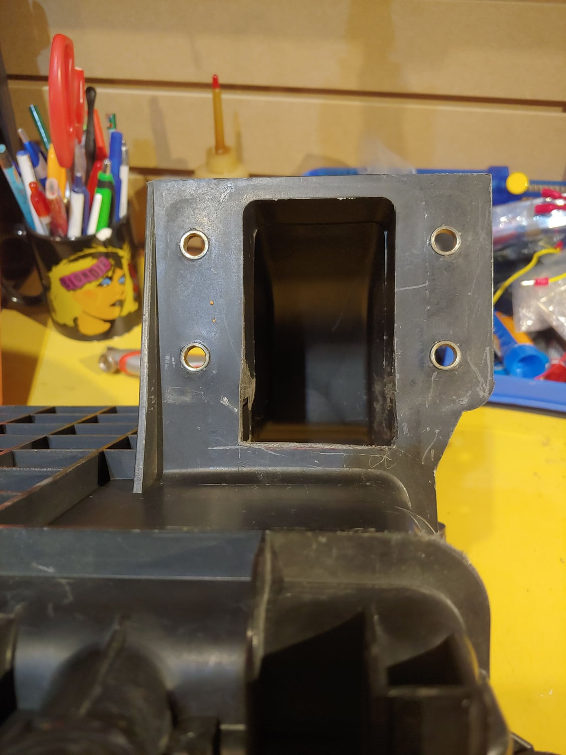
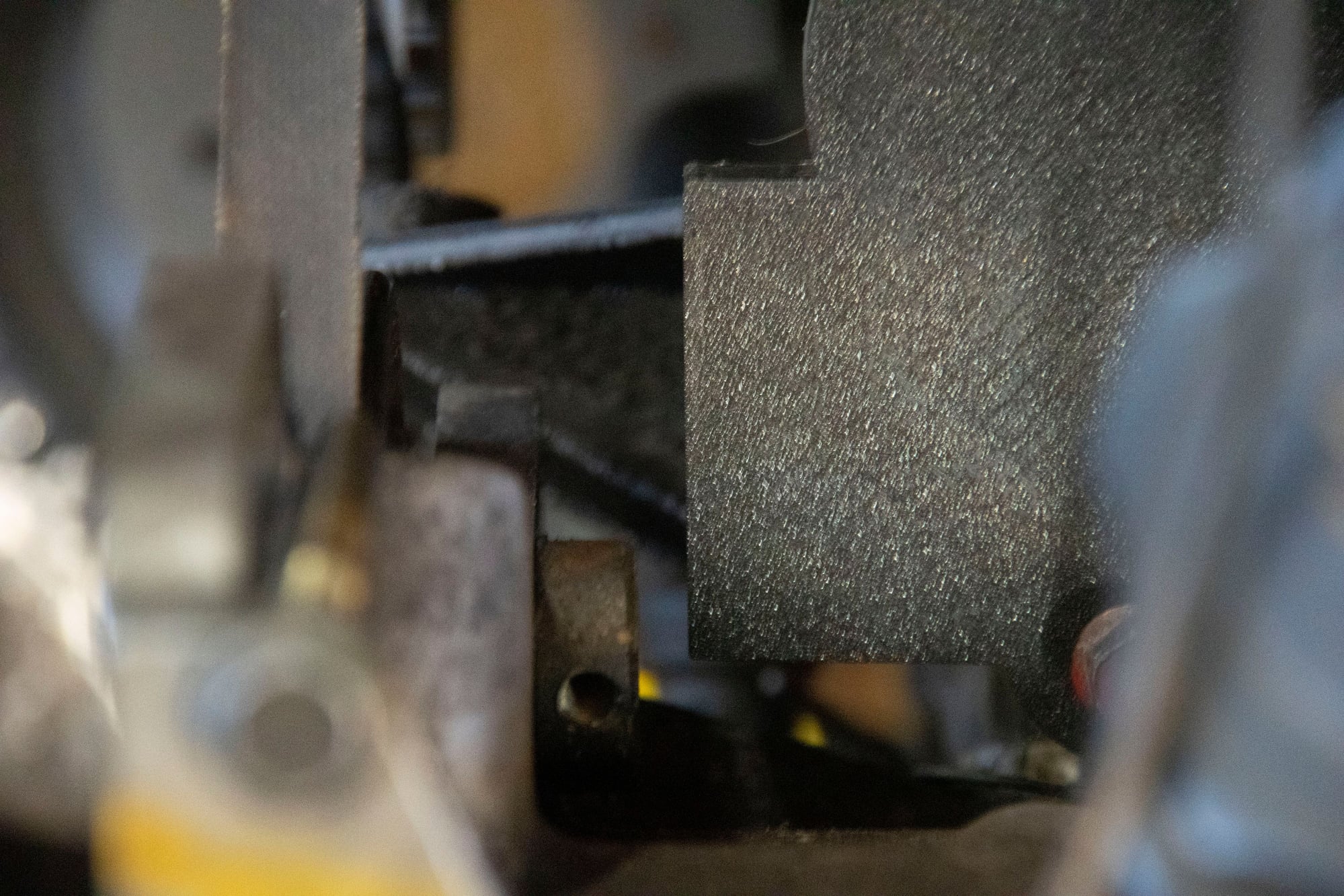
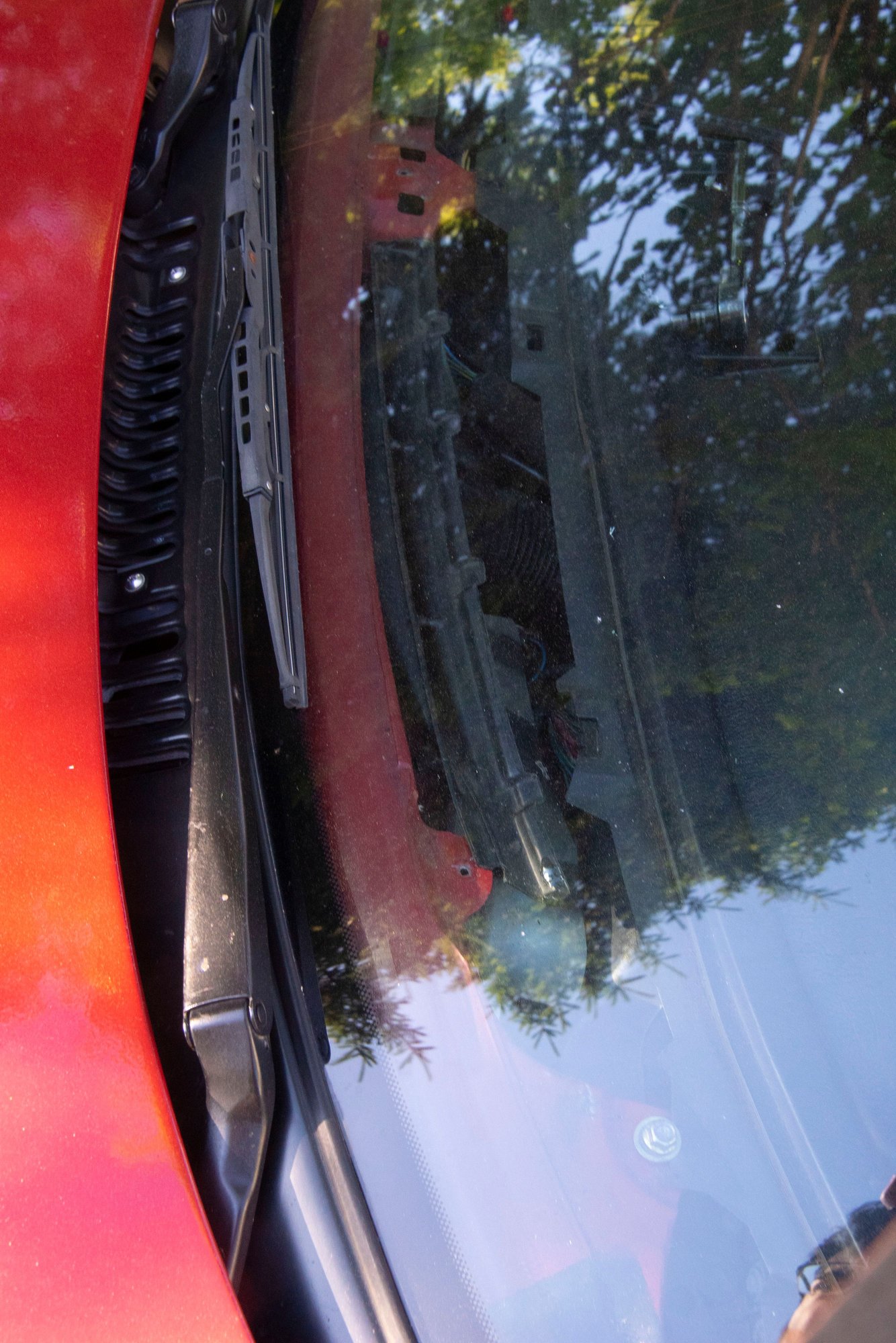
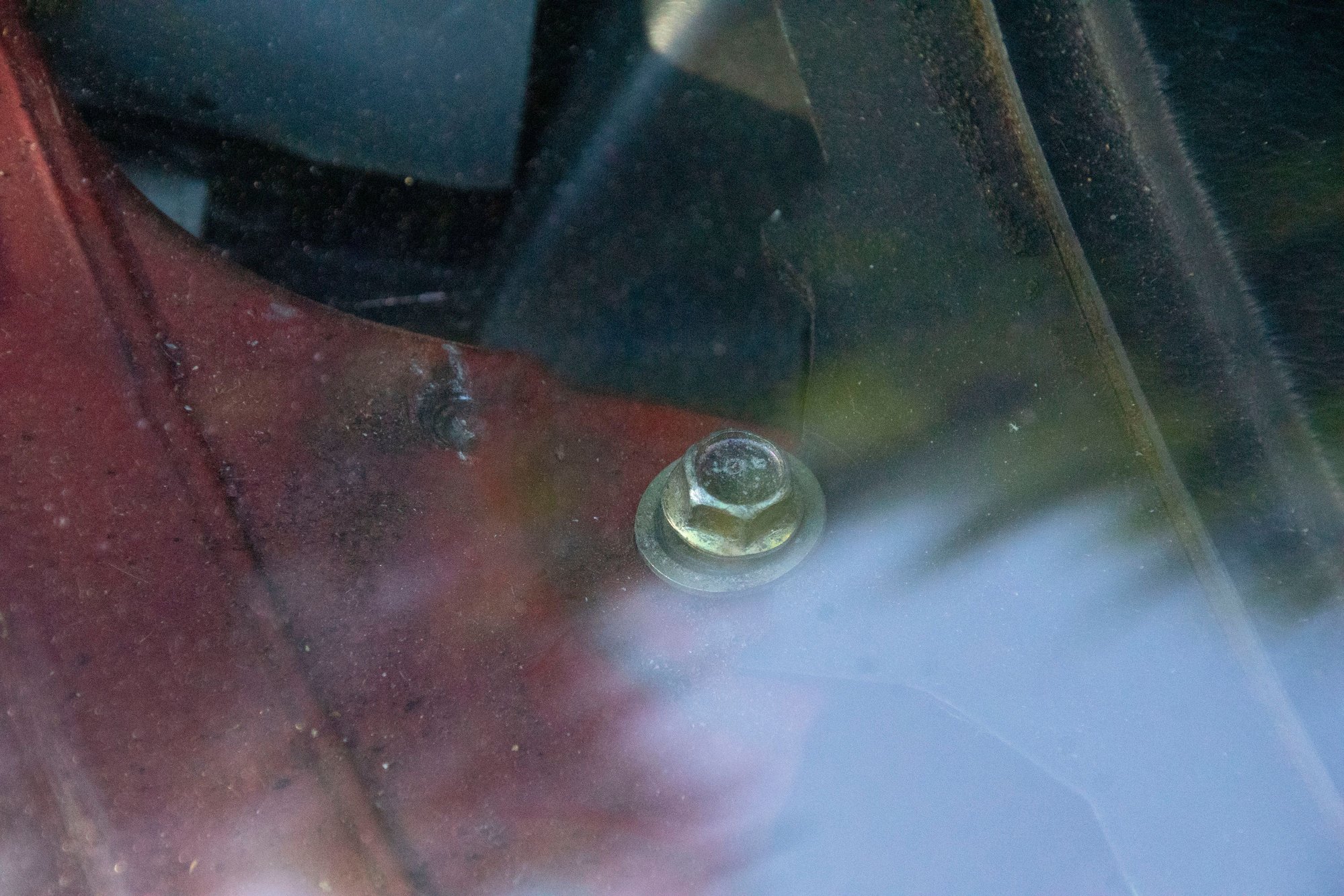
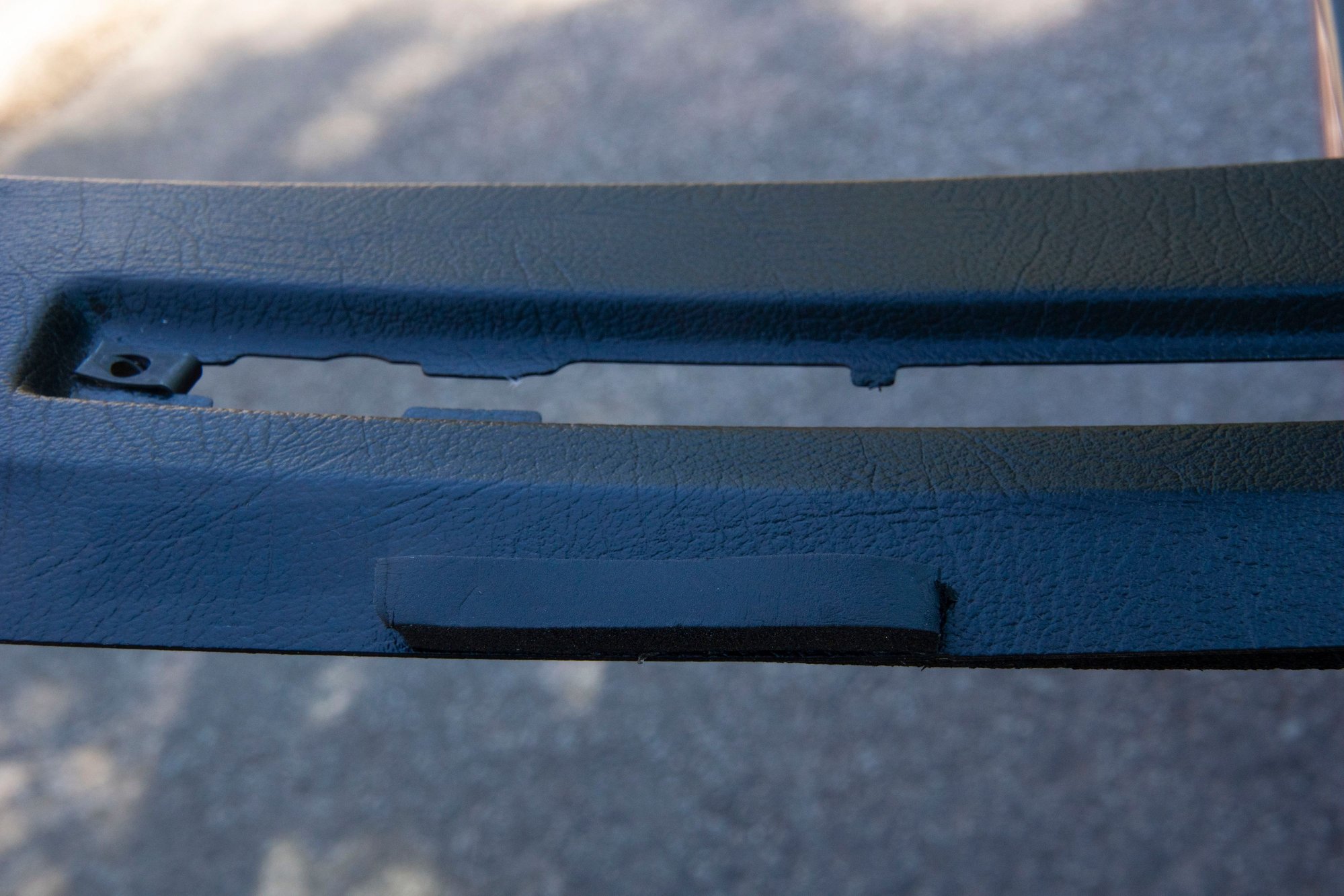
Speaking of Mazda's stock design, I also noticed something weird. The outlet of the airbox had this rectangular piece in it, reducing the surface area of the opening at the top of the outlet. I can only assume they wanted to use off-the-shelf Denso MAFs and decided the opening didn't need to be any bigger than the rectangular MAF inlet, which makes some sense. But now that I am not using the Denso MAF that restriction can go:
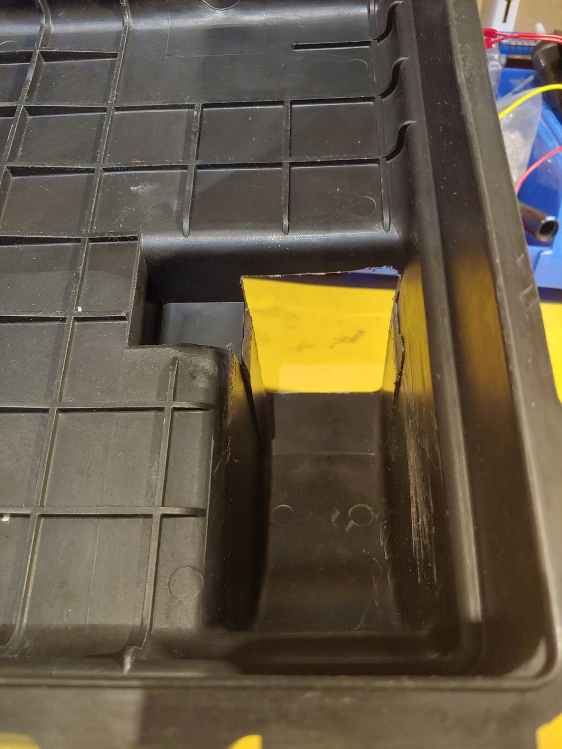
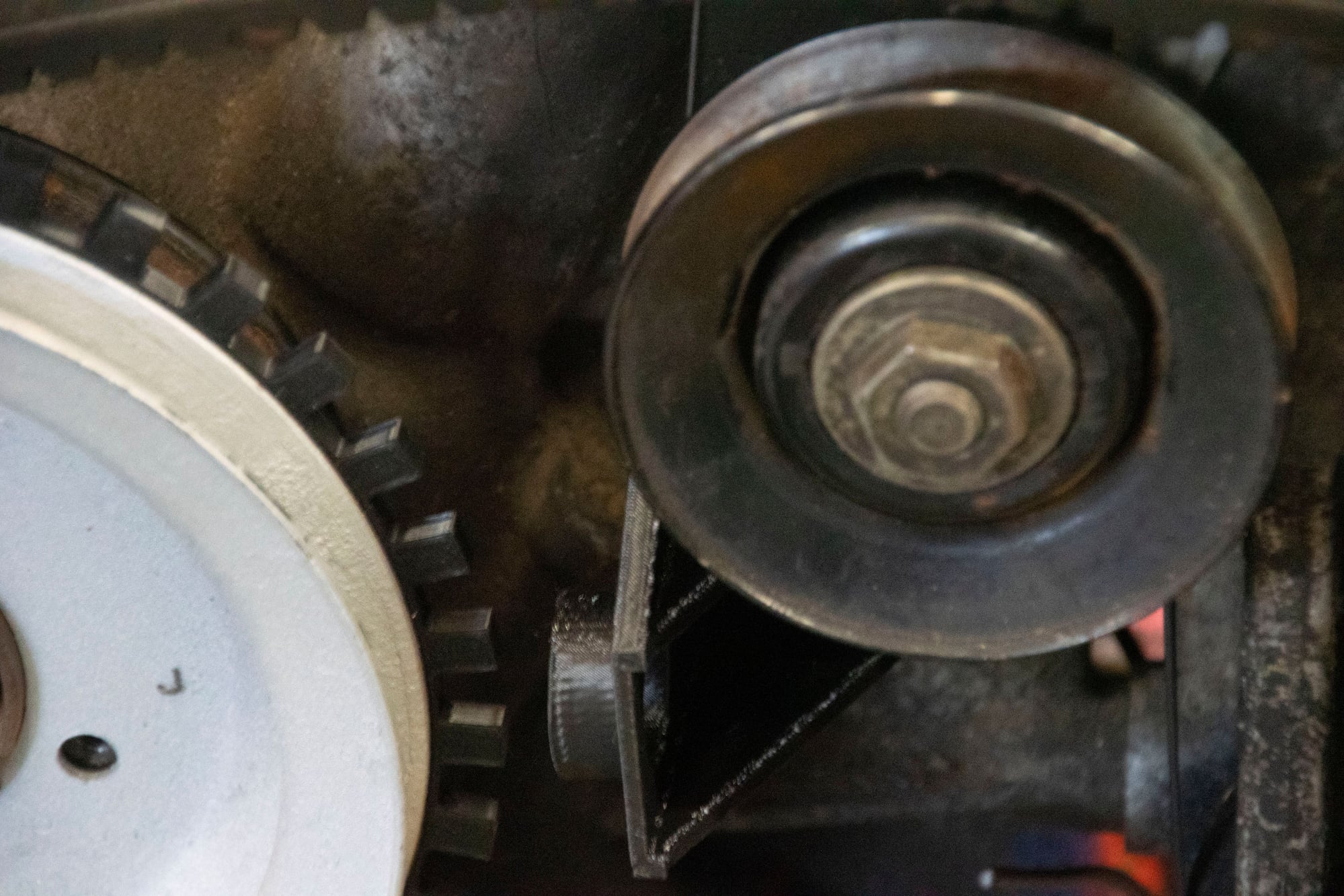
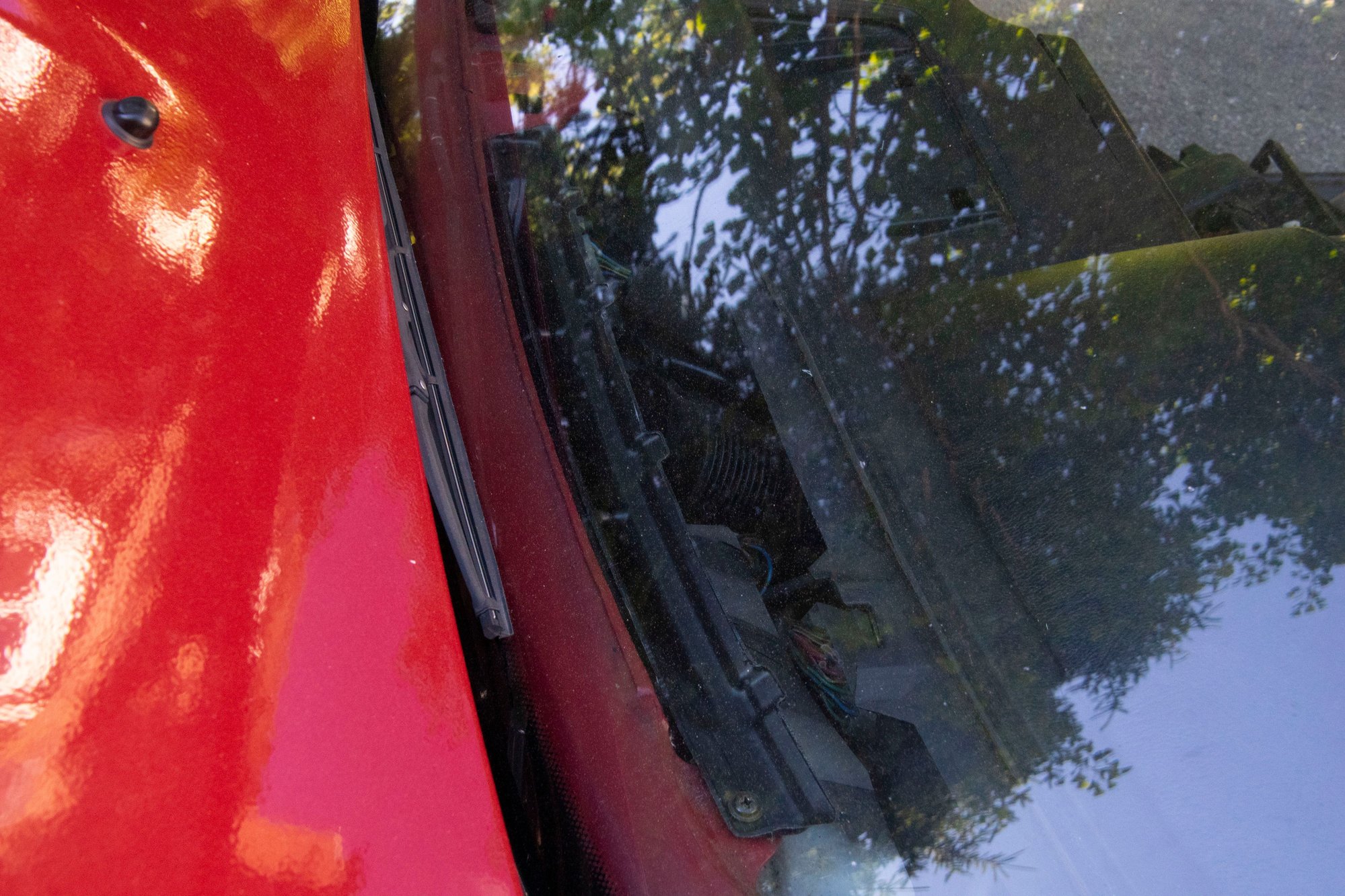
And the rectangular piece also covered this side near the filter:
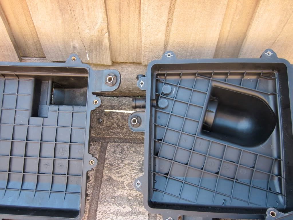
I found this picture that shows the original lip thing (left) as well as a comparison with the S5 airbox. The S5 has a much larger valley where it transitions from airbox to filter, and it's located more central to the filter as well. I kind of wonder if there are any more gains to be had here, but if there are I doubt it's anything substantial.
With that, everything gets bolted up and put into the car. The wiring was very simple, I just made a little sub-harness and ran it down to the ECU. +12V, signal ground, power ground, signal.
Then I needed to make the relevant ECU changes:
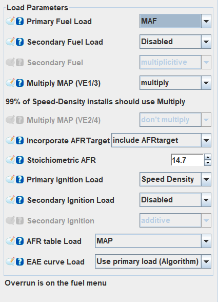
This might look confusing because I'm still using speed-density on it, but hear me out:
- Primary Fuel Load (the way the MS3X calculates how much fuel to inject at any given time) is changed to MAF. I'll discuss how this affects tuning shortly.
- Primary Ignition Load and AFR Table Load are still speed-density. This lets me use my old tables as-is, without having to rescale the y-axis. If I changed these to MAF then I would have to find out the relationship between manifold pressure and air flow and scale the y-axis appropriately for my old values to work. I should note that I DO intend to do this in the near future once everything else is 100% worked out. It's just that for now it was much easier to start with known good ignition timing and AFR values.
Then I had to set the MAF settings:
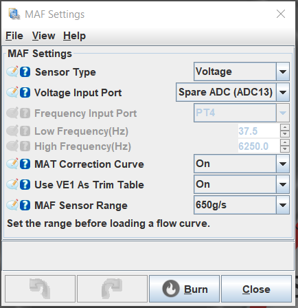
- The Z32 is a voltage type sensor. Many modern sensors are frequency type, so look into that if you are doing a similar conversion.
- MAT correction curve allows a percentage correction for the MAF based on the intake temp. This can be useful if your MAF becomes inaccurate with heat-soak, but wasn't necessary for me. While the setting is enabled I have that curve zeroed out.
- Use VE1 as trim table is a way to enable the VE table as a multiplicative correction on MAF. I'll explain what this does later, but again, it's enabled in my setup but I am not using it (table is set to 100 across the board).
I don't really know what sensor range does other than possibly affect the visual scale and initial values of the flow curve in settings. You need to manually input the flow curve values for your particular MAF anyways. I selected 650g/s because it was the closest to the values I found.
Speaking of values, I started with an "official" Nissan flow curve I found online. Turns out it was 100% wrong for my setup, needing to be leaned out by at least 25% just to run.
So as a quick refresher, let's talk briefly about how speed-density tuning works:
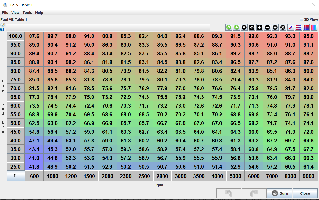
This is the VE table in a speed-density setup. You need to try and hit every bin and make sure the car is hitting your target AFR for said bin in open-loop:
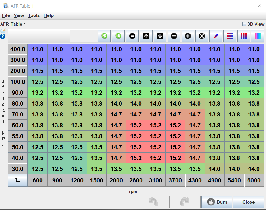
So if target AFR at 3100 RPM and 50kPa is 15.2, you want to adjust the equivalent VE cell until the engine is running as close to 15.2 as possible. Tuning for a specific AFR isn't good practice since we actually want to do whatever makes the engine happiest rather than hit an arbitrary number, but assuming the AFR target is correct we can try to get as close as possible by adjusting the VE number. These tables really need to be tuned in tandem, finding the AFR that the engine wants at the same time as you find the VE that achieves this AFR, and then putting that target into the table for the closed-loop.
The complication is that there is no real "link" between those tables other than in closed-loop when the ECU is trimming fuel to try and hit the targets in the AFR table. The other thing is that high load + low rpm is not the same as high rpm + low load in terms of airflow in the VE setup, so you need to try and hit a bunch of awkward bins (go up a hill at 1500rpm in 4th with the pedal flat to hit the top left, or travel at 7000rpm with the throttle cracked open doing 40kph to tune the bottom right). It complicates things a lot without a dyno.
Then once the VE table is as close as we can get it, the closed-loop algo should take care of minor variances.
In comparison, here's what MAF tuning looks like:
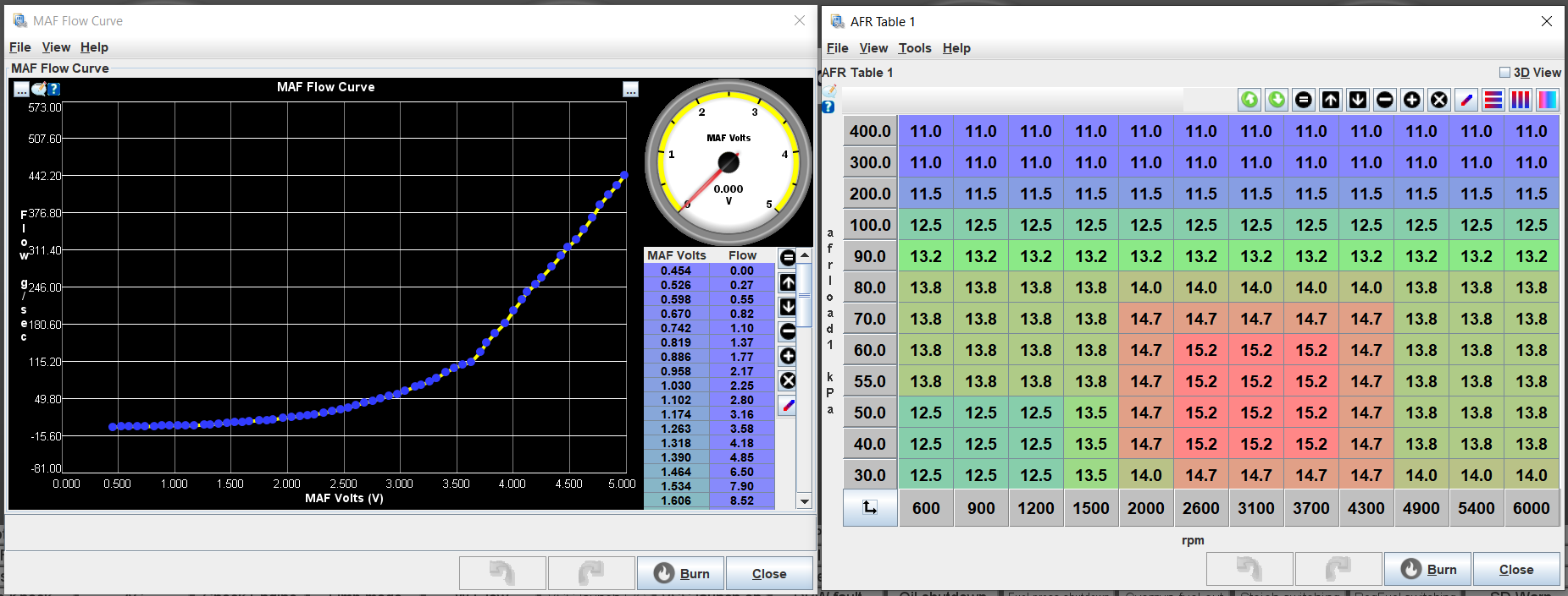
With MAF it's entirely different. Instead, I only use one curve and a table. The curve on the left represents the flow rate of the MAF (grams of air / sec) at a given voltage. The ECU doesn't have to take the VE number and do any math with the MAP, it just takes that number (say 1 gram) and then multiplies it by the target AFR for that bin. So at idle the ECU is just taking ~2.8g of air and using the air-fuel ratio to calculate how much fuel is required, then opening the injectors the appropriate amount.
The left axis still shows kPa in that AFR table, but the ECU isn't actually using it for any calculations. All the ECU is using MAP for is to know which AFR to target based on that table, and then otherwise the sensor is basically not used. This means that (assuming the flow curve is correctly calibrated) the AFR table itself dictates how much fuel is injected. If I want to idle at 13, even in open loop, I just drop 13 into the desired cells. Or 14, or 15, etc. I don't need to change the cell values in the VE table and then see what happens on the wideband and tune it in. It just works. If it doesn't, then either the calibration is wrong for that flow rate or there is a vacuum leak / other issue. The reason my curve is choppy above 3.7V is that I can't make it flow more with my current engine. That value is only ever hit when I'm in 4th gear going at a pretty good clip, and I would need to be going very fast to flow more air in an NA car. Turbo car should be able to do it under hard accel.
Closed-loop works the same as in the speed-density setup, it just doesn't need to do as much work.
Now I mentioned before that I had to tune the entire flow curve myself because the ones I found online were way off. I didn't really go into how to do this yet. Take a look at this log:

The right side shows the AFR table, but the important part is on the left. The second box from the top shows AFR and AFR error. So it's targeting 14.1 but it's 0.1 off of target. I can also see the MAF volts and flow at the bottom. So this part of the curve is pretty well tuned, but if not I would open TunerStudio and increase or decrease the g/sec value at 1.769V.
I also have an equation I made to do it for me which is why there's a "Calculated MAF" value. That's a custom field that takes the MAF g/sec reading (red line, 12.510 volts) and multiplies it by (Measured AFR / Target AFR) to make a "corrected" value I can drop into the curve at that point. Users on MSExtra were kind enough to offer some help and also show me that MLV has a histogram function that lets you define the scale:
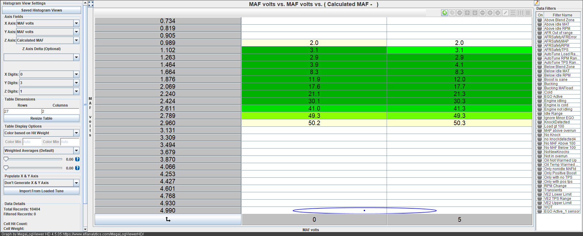
So basically the scale on the left has the same voltage units as my flow curve, and the histogram on the right shows the average of all Calculated MAF values. This means I don't need to hit an exact voltage value and hold it either, since MLV will do the job of fitting the values to this scale for me. I can just take a nice long drive and then copy / paste these values into the flow curve. The darker the green colour, the more "hits" at that voltage value during the drive and the more accurate the number is likely to be.
It's not a perfect system. I found it took several attemps because my equation will overshoot slightly. If it's targeting 13 AFR and measuring 12.5, and I take the Calculated MAF value for that and drop it in the curve, next run I'll measure 13.2 under similar conditions. Run it again and put in the new value, I'll get 12.9. It needs to be done again and again until the curve smooths itself out.
This would be a great opportunity for the Tunerstudio developers to create an autotune for it, but they haven't. The VE "correction" table can be autotuned, but that tends to result in some weirdness because it's still trying to use two independent variables (MAP and RPM) to calculate the correction value for something that only has one independent variable (airflow). So it doesn't seem to work very well when used that way, but then the developers didn't seem to intend it to do that in the first place.
And what's the result?
First off I have yet to re-enable closed-loop and the car is almost always within 0.3 of target AFR. Usually 0.1 at steady state conditions. It's super accurate even without correction, and I can probably get it even closer by tuning the curve more. Second, I need almost no acceleration enrichment or after-start enrichment. I also noticed it's much smoother returning from decel fuel cutoff, and throttle response is generally improved. The MAF reacts so quickly to the changes that the speed-density algorithm struggled with. Third, the tune doesn't drift with outside temperature anymore. I thought it did until I got the flow curve dialed in, and now it's rock solid all the time. I don't need the closed-loop algo to help with hot starts anymore.
The only thing I have yet to tune out is that it runs a little lean after warmup ends (at 176 degrees) for 5 minutes or so before running properly and hitting target AFR. Meanwhile if I'm driving the car on a cool day the coolant often drops below 180, so I can't keep the warmup enrichment on longer or it activates when already warmed up. Still haven't figured that one out yet. The closed-loop algo can probably handle this but I'd rather tune it out the proper way if I can.
Overall I'm really happy with how it turned out. It was a bit of an adjustment to how I had learned to tune, but the results were well worth it. Until next time :)



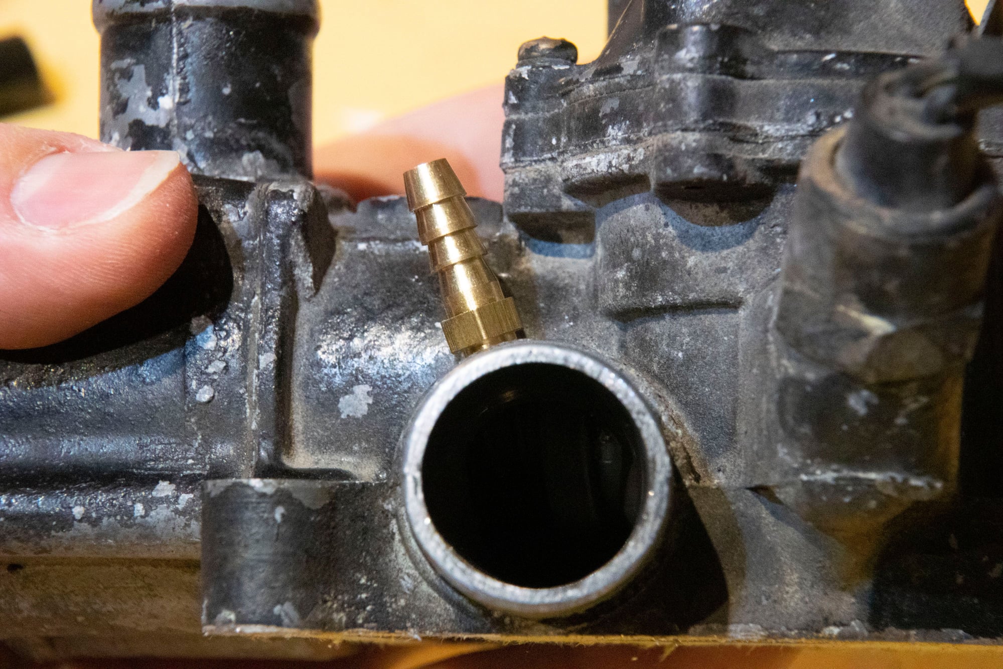
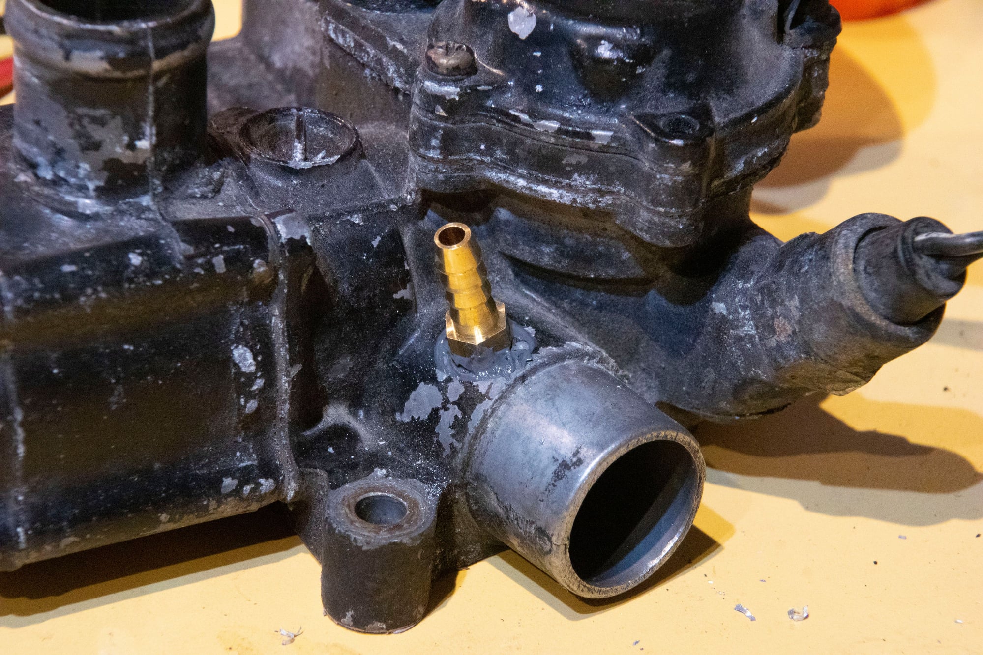
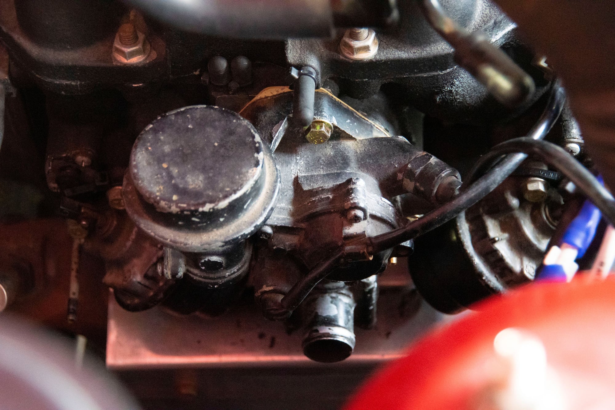
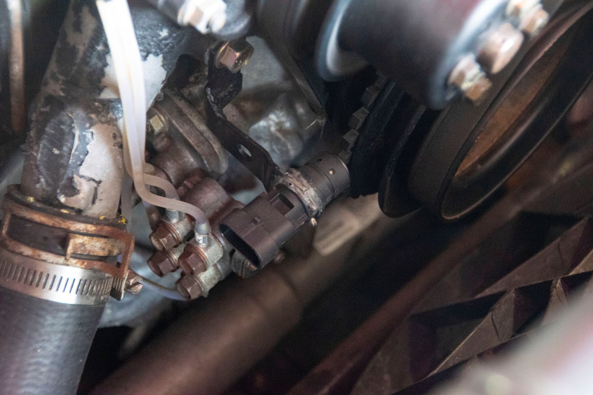




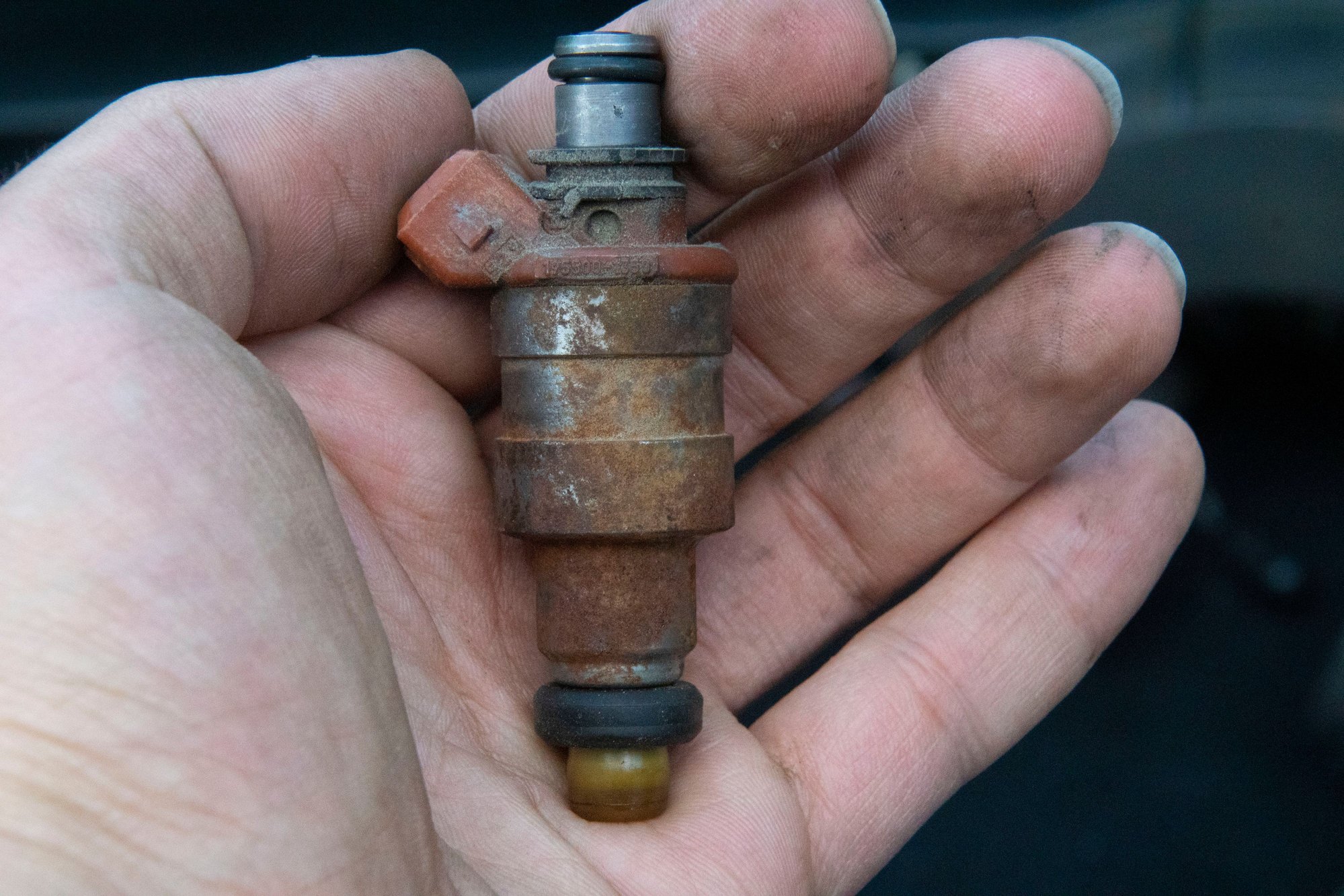
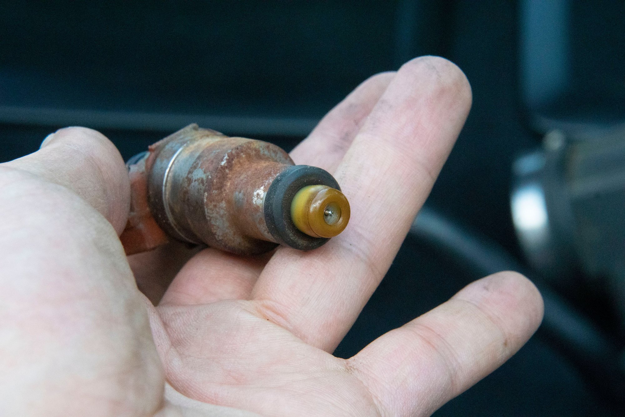
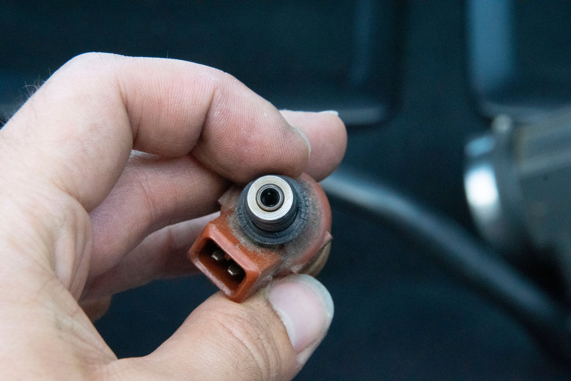
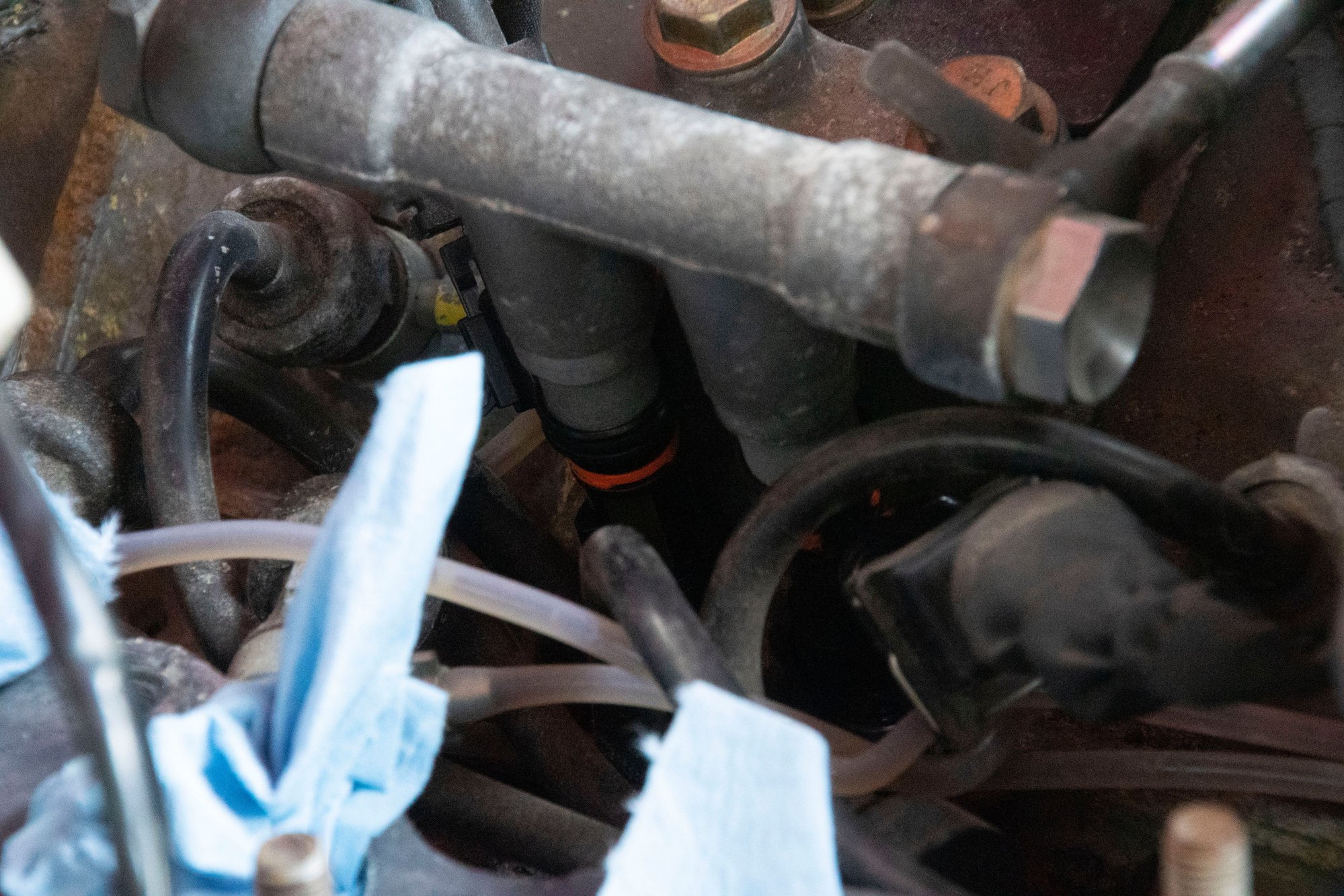
 (there's no emoji that properly conveys "terror" so there's my best attempt). Fortunately a more experienced associate was there and immediately jumped in to correct him, but man, if there was no one around and someone tried using garden hose for their fuel system that could have ended in disaster.