7 8 9 10
WondrousBread
WondrousBread Reader
7/26/24 10:13 p.m.

I just can't leave well-enough alone!

My car runs very well with the Z32 MAF, but I felt like there was some area for improvement. I noticed that the signal would bounce around a lot (a lot only being 0.05 or 0.1 V, but that is significant in MAF terms). This wasn't much of an issue except that I had to turn up the MAF Averaging setting to smooth it out a bit, and this setting dampens response time which means you need more acceleration enrichment correction. I also think that the Z32 design suffers a bit from reversion because the wire is sitting in the open. So air can bounce back and swirl in the pipe and the Z32 design might be more susceptible to noise. Lastly, there was some noise in the system even with the car off which leads me to believe the sensor itself is a bit finicky.

I decided to give the R35 MAF a try. It seems like there are plenty of variations on this sensor design (the slot style) and also lots of people using them in standalone applications. The sensor is designed to minimize reversion and also includes an integrated IAT sensor. I thought that it would be easy to find data for this sensor as well, although I failed to account for the fact that the different variety of slot style sensors makes it difficult to find the correct voltage curve, and also that Hitachi doesn't actually make the datasheet available for this sensor. But those are solvable issues.

I picked up a sensor (Hitachi MAF0031) and wired it up to test:


0.34V at zero airflow. Blowing on the sensor changed the reading which confirmed I had the wiring correct.

I found a helpful document that showed the pinout, but the IAT sensor had some confusing nomenclature. I expected it to be a simple thermistor,but the phrasing in the document called one pin "IAT Signal" and the other "IAT Ground". This had me wondering if it was a 0-5V sensor powered from the same 12V supply as the MAF sensor, but it turns out that the document was just awkwardly phrased. It is, in fact, a plain old thermistor:


Before the sensor arrived I had actually started designing the housing. I needed a mounting boss for the sensor and didn't find a free 3D design for the boss on it's own. Either it was a paid design or it was already part of a tube. So I found this diagram and made my own.

Step one was to import the diagram into Fusion 360 as a canvas:


There's a very convenient function in Fusion that lets you pick two points and provide the distance between them, then the software will automatically scale for you. In this case I used the two bolt holes.

Then I spent a few minutes drawing all of the lines:


And a few more extruding:


Done. I'm glad I started learning Fusion; Blender would have taken ages to achieve the same result. Not that Blender is bad, but it isn't really designed for CAD. I fell into the trap of becoming comfortable with the software I knew rather than trying to learn something more appropriate for the job. Using Blender for CAD is like deciding to cut down a tree with a hand-saw when a chainsaw is available that will do the job in 1/10 the time (Fusion).

I imported an existing adapter tube from Thingiverse. I've used this tube in the past when I was running a speed-density tune, and it works really well (as long as it's printed in something like polycarbonate that can withstand the heat). The only tricky thing is that since it's an STL mesh and not a solid, it's not as easy to modify in Fusion.

I located the sensor boss as far back in the tube as possible, and made an educated guess with a set of calipers to try and locate the opening for the hot-wire right in the center of the tube:


Then used Fusion's excellent "To Surface" setting in the Extrude tool:


Lastly, Extrude-Cut the opening for the slot:


I printed one with my remaining PC filament, but unfortunately ran out just before the end of the print. It was certainly good enough for testing though:


The fit on the sensor is about 90% of the way there. I moved the sealing surface on the inside of the boss up 0.5mm, and the flats the screws tighten up against also up 0.5mm.


I did a pretty good job centering the hot-wire too. I later revised the design and moved it down a few more millimeters.

To be continued

WondrousBread
WondrousBread Reader
7/26/24 10:14 p.m.

While waiting for another role of PC filament I decided to test out the sensor using the first tube I printed. I took out the airbox (a literal 2 minute job, I love working on FCs) and realized I had completely forgotten to account for clearance when designing the tube:


It's a really, really tight fit due to the shape of the airbox:


But happily my new design still fits:


The next one (printing as I type this) moves the sensor down about 5mm, so clearance is even better. Changing the sensor will still be an airbox-out job, but like I said before that isn't exactly an arduous task.

Lastly, I wired up the sensor by just connecting the exposed pigtail wires to the Z32 connector I added to the harness last time:


That's obviously for testing purposes only, and to shake out any possible issues without making a permanent change to the harness. The IAT wires are just extended over to the stock connector on the dynamic chamber.

I couldn't find the calibration for the thermistor, so I took a resistance reading at room temperature and compared it to a plain old mercury thermometer. Then I did the same comparison at 45C with a heater, and also at -20C in the freezer. This lets me input the three points into the MS3X and it will generate a curve. I kind of don't like how this feature is implemented (it would be nice to see the curve) but it does work.

I also couldn't find a flow-curve for the stock sensor. There are plenty out there for the PMAS HPX sensors but I couldn't find a stock R35 curve. I decided to just fire up the car, and I was able to get a (crappy) idle by multiplying my prior curve by 1.5 or so. I found that the reading wanted to jump around a lot (more so than the Z32 sensor even) but that can also happen when the engine is running poorly and vacuum is inconsistent so I don't know whether it's a problem yet.

I was also operating under the assumption that the two curves had a similar slope. Simply multiplying the curve by some number (in my case 1.5) assumes that both curves are increasing at the same rate as the line moves rightward. Meanwhile if the Z32 flow increased by 15g/sec from 1V to 2V and 100g/sec from 2V to 3V (arbitrary numbers I chose), there's nothing to say the R35 MAF couldn't increase 15g/sec from 1V to 2V and 45g/sec from 2V to 3V. I'm probably not explaining that well, but that's the best I can do.

With my current flow-curve obviously insufficient, I played with the PMAS HPX transfer function generator to try and get a better curve. The generator tool is an Excel spreadsheet that allows you to input the diameter of the pipe and then returns a flow-curve. This is what it gave me:


I'm not using all of the resolution the MS3X gives me, since I haven't rescaled the curve. But assuming it's in the ballpark this should be good enough for testing until I rescale and actually spend time tuning it. I should have the new tube printed by sometime tomorrow, so if all goes well I can take it for a drive and see what happens.

Until next time

WondrousBread
WondrousBread Reader
8/12/24 7:53 p.m.

I was able to fix the 3D printer for about $40, but I ended up returning the MAF I bought. One thing I noticed was that when idling the signal would jump around (a lot, much more than the Z32 sensor). I also noticed that there were no part numbers on the supposedly "new OEM" Hitachi sensor, and some scratches from it being installed previously. I assume the Amazon seller was selling used aftermarket parts instead of OEM, and I didn't really feel like investing the time to tune a sensor of unknown quality and origin. I will pick that project up again sometime with a proper OEM MAF.

I ended up spending a bit of time and money on something entirely unrelated - the steering wheel. But first here's a refresher on my adventures with the prior steering wheel (feel free to skip to the photos if you aren't interested).

When I bought the car it had the stock 380mm wheel. This is a slightly larger size than normal, and like most people I kind of wanted a 350mm wheel but didn't really feel like buying one since the stock wheel worked fine. I did however have one strange issue which is that the horn would go off randomly. I had already resoldered the body CPU more than once and failed to resolve this issue, and I noticed that it would only happen when turning the wheel (and only sometimes).

This came to a head when the horn started blaring in a Tim Horton's parking lot and wouldn't go off (terrifying some poor old man trying to park his car nearby). I just ended up lifting the hood and pulling the negative cable off the battery with my hands (yes, I've replaced the terminal since then) and then reaching my hands through the grill and unplugging the horns.

Driving around without a horn isn't safe, so I ended up buying a "genuine" Momo wheel on eBay and an NRG short hub. Then when they arrived I realized that the wheel hit the turn-signal paddle and I needed a spacer to push it away from the dash. The spacer I picked was a shiny one that I kind of liked at the time but would later be a bit too "busy" for my taste.

Oh, and the problem with the original wheel? Well there was no obvious issue that would cause the horn to go off, but eventually I shook the wheel in just the right way and a tiny little screw fell out. It wasn't an OEM screw and I have no idea how it found it's way into my steering wheel. I assume that every so often it would land in just the right place and bridge the contacts for the horn button before falling back out again.

The new wheel worked fine for a few years, but I carelessly bent it last year (or the year before? I don't know anymore). A shop that had done an alignment for me a few years back cranked the NRG hub down on the column so hard that it started to damage the splines on the hub, and bottomed out the hub slipring against the sprung contact for the horn (if that doesn't make sense there will be photos shortly). I was able to later pull the hub off the column directly, but not before putting a small (but noticeable) bend into the wheel itself.

I could live with a bent wheel (I have better ways to spend my money) but then a few weeks ago someone cut me off, and when I pressed on the horn button it just blew apart in my hand. Gee, I sure showed that guy! Turns out the plastic in the horn button was very brittle after almost a decade and it finally gave out. So now I was in the position of needing to replace the button, as well as wanting a non-bent steering wheel and a less eye-catching spacer.

I grabbed another "genuine" Momo wheel off eBay, and supplemented it with a "genuine" Momo quick-release. It does the same job as the spacer, except all black and with the added safety benefit of being able to remove the steering wheel quickly in an accident. It's fairly unlikely I'd survive an accident since most of the cars on the road nowadays are trucks with a hood-line higher than my head or 5000lbs SUVs that could drive up my car like a ramp, but every little bit helps.

Here's the old wheel:


It actually felt really nice to drive with. The bulges at 10 and 2 made it really easy to grip. However, the whole wheel doesn't really "fit" the aesthetic of the car in my opinion. It's not terrible, just a little bit out of place.

Speaking of out of place, here's the spacer:


Too shiny. And speaking of out of place (again), here's the issue I mentioned with the horn slipring:


The hub isn't supposed to sit down that far on the column. Instead of the horn contact being held against the slipring by spring tension, it's compressed against the slipring. I had fixed this issue in the past, but due to some damage to the splines it doesn't require that much torque to compress it down this far. A new hub is probably a good idea, but I'll get to that later.

Looking at the hub, I also had to address a design flaw. The slipring and the plastic ring it fits onto can move a little bit independently of the hub itself. This causes the wire for the horn to bend a bit and then eventually it breaks. This is of course aggravated by the extra friction on the slipring from the over-compressed horn contact, which means when I turn the hub the slipring really does not want to turn with it (placing tension on the wire):


So I designed a little tube to take up the slack:


Resoldered a new wire (had to center the wire in the middle of the solder joint or the tube won't sit flat):


Dropped the tube in:


Put the whole assembly on the back of the hub:


And there we go. I put a dab of hot-glue on either side just for some strain-relief and to prevent any rattling.

With that done, I had to install the quick-release. It's a bolt-on install, but the height of the Rx7 column nut will compress the wires for the horn when installed and could wear through the insulation. So I had to use a file to grind a little channel for the wires to go into:


I also reattached the ground wire using that little threaded hole, but forgot to photograph it.

Then the wheel bolts onto the front part of the quick-release, and it clicks into place:


All black, and complete with speed-holes!

Clearance for the horn button is very tight, so I made some custom wires:


This still barely clears, but with the spring for the horn button installed (not in the photograph above) it fits securely.

To be continued

WondrousBread
WondrousBread Reader
8/12/24 7:54 p.m.


Overall it works pretty well. I was able to carefully find a sweet-spot between installing the hub securely but not bottoming out the horn contact, so I can get away with using this hub. I used blue Loctite to be safe and have been checking every couple of days, no sign of the nut loosening yet.

Despite it looking a little bit cheap, I really like the pleather on this wheel. It's grippy enough that it doesn't slide around, but smooth enough that loosening my grip when exiting a corner lets the wheel return naturally. Speaking of which, the poor returnability of the steering wheel that I had been experiencing is basically gone. I think it was a combination of friction from the horn slipring and some friction from the steering column trim (which I trimmed back a bit further when I had it off).

The only thing I'm not super happy with is how far the wheel sits from the turn-signal paddle:


This is the sort of thing that wouldn't be a problem on most cars but is a problem on Rx7s due to Mazda's weird choice to use a paddle instead of a stalk for the turn signals (and cruise control, if equipped). I actually really like the paddle, but it does make the steering wheel situation a little weird. I think I can get used to it though.

Until next time

Indy - Guy
Indy - Guy UltimaDork
8/12/24 9:35 p.m.

In reply to WondrousBread :

Nice work. Wheel looks good 👍

WondrousBread
WondrousBread Reader
8/19/24 4:08 p.m.

Light on photos this time, but I always try to log even minor repairs so I can refer back to them in a few years when I've forgotten them. I have a terrible memory. You wouldn't believe the number of times I google an Rx7 related question and find my own answers from years ago.

This actually took place a few weeks ago, but I was driving near my house and when I changed into second I got a really big "CLACK" noise from the transmission. I was on it pretty hard (around 7500rpm) but even so, that shouldn't happen.

When I got home my dad asked if I was sure I had my foot all the way down on the clutch, and I was. But it did raise the question of whether the clutch was properly adjusted. I remembered two things:

1. The clutch master and slave had both been replaced, but the fluid in the reservoir would still turn black and need to be replaced every few months. I had been putting off replacing the hose.

2. I have never adjusted the pedal freeplay in the clutch.

I figured I would try the freeplay first and then look at the hydraulics later. The freeplay is adjusted by loosening a 12mm lock-nut and then spinning the pushrod on the pedal in or out. You don't need to mess around with removing the c-clip and clevis pin - ask how I know. Adjusting the freeplay so that there was only about 1/2" of space at the top of the pedal seemed to work and I was pretty happy with it.

I thought about putting the hydraulics on the back-burner, but the decision was made for me when I was moving the car in the driveway and the clutch pedal stopped coming up. My dad helped me roll the Rx7 back into it's spot and I took out the old hydraulics:


Now the only original part here should be the hose, but as I was changing this out I got to thinking how foolish it was of me to continue using a 38 year old rubber hose. The fluid has been changed more than once and it still came out looking like the black goo from the X-Files. I can only assume this is from the inside of the rubber hose, although I thought they were PTFE lined so maybe it was something else.

About $80 on Rockauto got me some brand new parts:


I sprung for the Exedy cylinders, and I think the hose is a Dorman? They all seemed to be really good quality.

I didn't take any pictures of the process (I rarely do when hydraulic fluid is involved). Removal and re-installation took a cumulative 30 minutes. I think even the bleeding process only took like 10 minutes total, plus 5 minutes vigorously washing anywhere that the fluid may have dripped below the cylinder. After the replacement all is well.

I have been finding myself wanting a lighter flywheel and more aggressive clutch lately. The heavy stock flywheel is kind of nice when you're learning to drive (this was my first car 8 years ago) but once you're experienced driving manual, you can shift a lot faster than the stock flywheel will allow. Plus I notice that when my current clutch (Exedy stock replacement) is hot after a long drive it isn't as grippy as I would like. I can replace the clutch / flywheel in only a few hours, but considering that none of the parts involved (S4 counterweight, lightened flywheel, grippier clutch) would transfer to the Turbo II engine I'm not really sure whether I want to spend on it.

Until next time

WondrousBread
WondrousBread Reader
10/12/24 10:31 p.m.

I made a small change on my Rx7 recently. A long time ago I purchased this rear camber link:


It's the common style for the FC you've probably seen 100 times. By pulling the back of the rear subframe up or down, you can use it to adjust static camber on both wheels. This is a neat design that has a right-hand thread on top and a left-hand thread on bottom, so by loosening the lock nuts and rotating the center sleeve you can adjust it in-situ without having to remove either end. This makes it a lot easier to get an alignment at some known point and then dial it in later however I want.

There's only one problem, which is that it transmits too much NVH to the cabin for my liking. Now, there is an off-the-shelf solution from Mazdatrix:

https://mazdatrix.com/product/susp-c...86-92-rear-rb/

But frankly I think that's a bit expensive for what it is. Almost $200 USD, and it still requires you to unbolt one end to adjust it. So I started making my own solution.

First I measured the threads on the existing rod ends:


M14x2.0, 40mm threaded length. Finding appropriate threaded rod would prove to be a bit of a challenge, but certainly doable.

I purchased a stock camber rod a few months ago and finally got around to seeing what it was made of:


The inside is actually 13mm so you could possibly find some way to tap it for threads, but I wouldn't end up doing that. I actually thought this was a solid rod originally, and I had a weird idea to cut the link in half along the centerline and lathe it down to 14mm before using a die to cut threads. The hollow rod ended up making this easier because the new threads would self-center.

Speaking of new threads, I had some trouble finding 14x2.0 threaded rod near me. But I did find something on Amazon that would work:


Yup. I found it was actually cheaper to buy and cut up two new rod ends than it was to buy threaded rod in that size. The angle grinder made quick work of it:


I felt a bit weird cutting up a rod end to get threaded rod. Sort of like I was unmaking something rather than making something? It's like taking apart a cake to make flour.

After cleaning up the end using a bench grinder, I checked the alignment 10 times and then clamped it firmly in the vise and checked another ten times:


Then I went to work welding it. I didn't want to put too much heat into this piece lest I damage the bushing, so I did four tacks and then dumped it in some water. Then after it cooled I dried it off and did the remaining welds. Fortunately there was no damage.

Here's a comparison:


So you can see my idea here. All the benefits of the Mazdatrix piece except at a total cost of about $110 CAD (not including the camber link I already had). I had measured the link carefully so I could adjust it back to the desired length, and here's how it ended up:


And we're done. With it reinstalled, there is a noticeable (if not dramatic) difference in NVH. I think the next step is to replace my remaining poly bushings with OEM rubber ones, and I already have most of them in a box waiting. Since it's almost winter I might find the time to do it before spring.

More urgent though is the painful amount of body flex. Driving my Mazda 3 has made me used to a much more solid chassis. The FC is very bendy by comparison. My frame of reference is always skewed on this sort of thing since it was my first car, but the FC could definitely use some improvements. There are off the shelf braces available but of course I've decided to do things the hard way, so that will probably the next thing I post about once I have made more progress.

Until next time

WondrousBread
WondrousBread Reader
11/3/24 7:59 p.m.

I talked about wanting strut braces in my last post and I started on that project, but I realized there was a related issue I should address first. The alternator sits way too high.

For anyone who hasn't read that part of this thread, I'm using a Ford 3G alternator out of a Ford Taurus. This requires a custom bracket I made like 8 years ago and a small adapter for the wiring harness, as well as an upgraded 4 gauge alternator cable. This worked very well and got me 130A of charging power, but unfortunately it does sit a little high:


This is an old picture, but it illustrates the issue. The alternator is physically larger of course, but the bracket also moves the mounting ear up and to the left. This basically results in a translation of the entire alternator up a couple inches from stock. When trying to find a strut-brace solution, this means that off-the-shelf braces might not fit and any custom solution I build will need to be further forward and upward. It also probably won't fit with a top-mount intercooler so I would have had to find something else before swapping the engines.

Fortunately there is a solution:


If this looks familiar, it should. It's the exact same alternator internally but it's from a Ford Contour. The case design has a few things I like:

- Saddle mount so I don't need an adapter
- Adjustment ear lower so the alternator can tuck lower
- Positive terminal pointing upwards so I can easily install the cable

I wasn't sure it was the right one (some Contours apparently have a different front case design so the pulleys won't work) but it was $50 on RockAuto so I decided to gamble. I haven't even seen a Contour in about a decade, so I don't think I would be able to find a better deal on a used unit anyways.

I have a box of 3G spares to raid for a regulator and dual-v pulley:


Why do I need a regulator? Well, I don't exactly. The alternator came with a perfectly good one, but the Taurus plug matches the adapter already on my car:


Really it was just a time-saver vs. finding the Contour specific plug. Installed:


Then it was just a matter of swapping on the appropriate v-pulley:


And the alternator was good to go install on the car. I used many (many) washers for the saddle mount as it's a lot wider than the original one. I had read that you can just use the air-pump adjuster in the place of the stock alternator adjuster, but it didn't fit quite right for me. I ended up finding a spare alternator adjuster bracket I had, and then hammering it flat and shortening it. Then I added a mounting hole and bolted it up:


Sure, the adjuster looks a little weird. But it works fine and you can see how much lower it tucks. I'll also need to get another charge cable as mine is a bit too short to be routed neatly behind the alternator. The current routing is ugly but it did let me drive the car for now.

You can see how close it fits to the water pump housing now:


And comparing the height, you can see just how much space is gained up top compared to the Taurus alternator:


This alternator now fits 100% below the ridges on the dynamic chamber. I've also seen pictures of it bolted up with a stock intercooler, so I know it'll clear that too.

In other news it's officially winter:


I know winter has come when all the leaves fall off of the Ginkgo tree. They always fall all in one day, and that's not even 1/5 of them.


I'll update as soon as I neaten up the wiring for the alternator and hopefully I'll have a strut brace solution by then as well.

Until next time smiley

WondrousBread
WondrousBread Reader
1/25/25 9:12 p.m.

I've finally found what I hope will be an acceptable solution for the aux port actuation that I worked on in post 8 of this thread.

For new readers, I'm going to recap from the beginning. It also helps explain what my goals were with this project.

On a rotary engine the port timing is controlled by the footprint of the intake and exhaust ports. Smaller intake ports with an earlier closing time promote better idle, and larger intake ports with a later closing time improve performance (to a point, of course). In a piston engine this is normally controlled with a VVT actuator, but since there are no cams in a rotary engine, Mazda's answer to this problem are the auxiliary ports:


These ports have sleeves inside of them. Normally the sleeve is closed, which means that the engine runs only on the smaller port (closing at 40 degrees). This is helpful for idle and midrange, where the extra port area kills air velocity. Then at higher load, a set of actuators rotate the sleeves, opening the port:


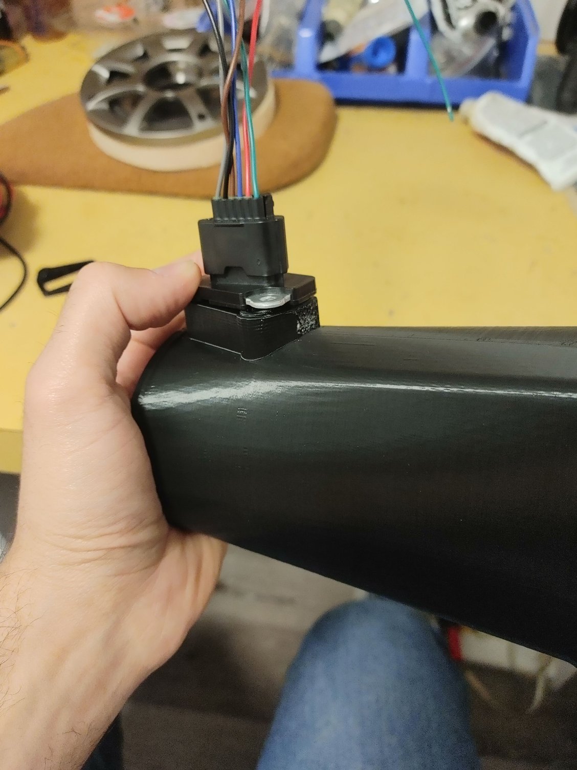
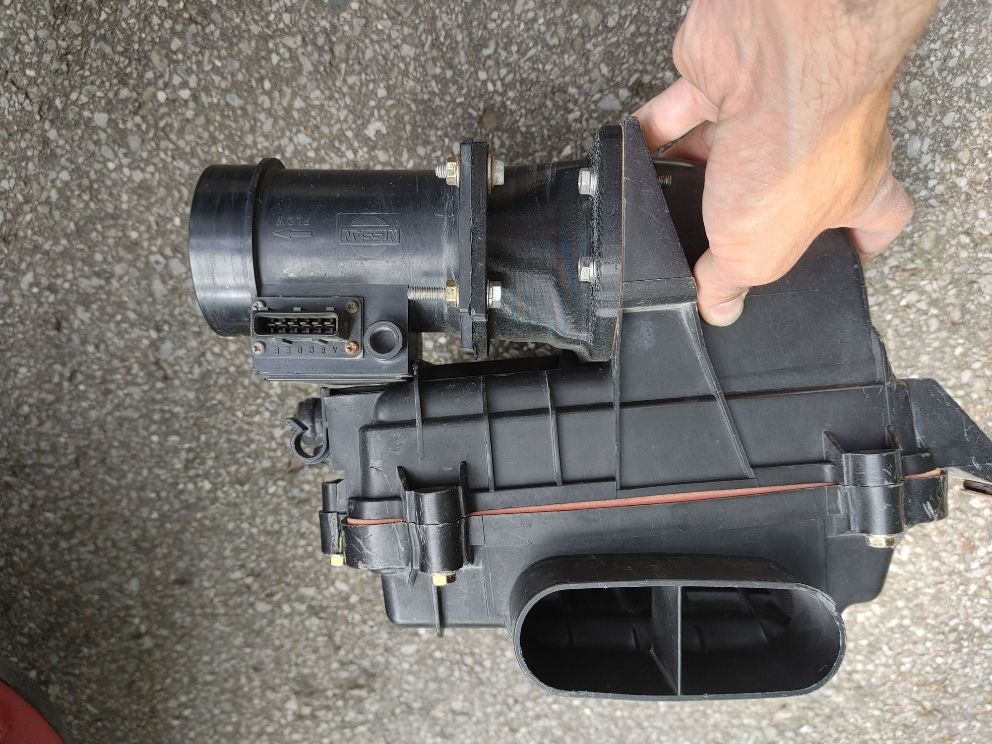
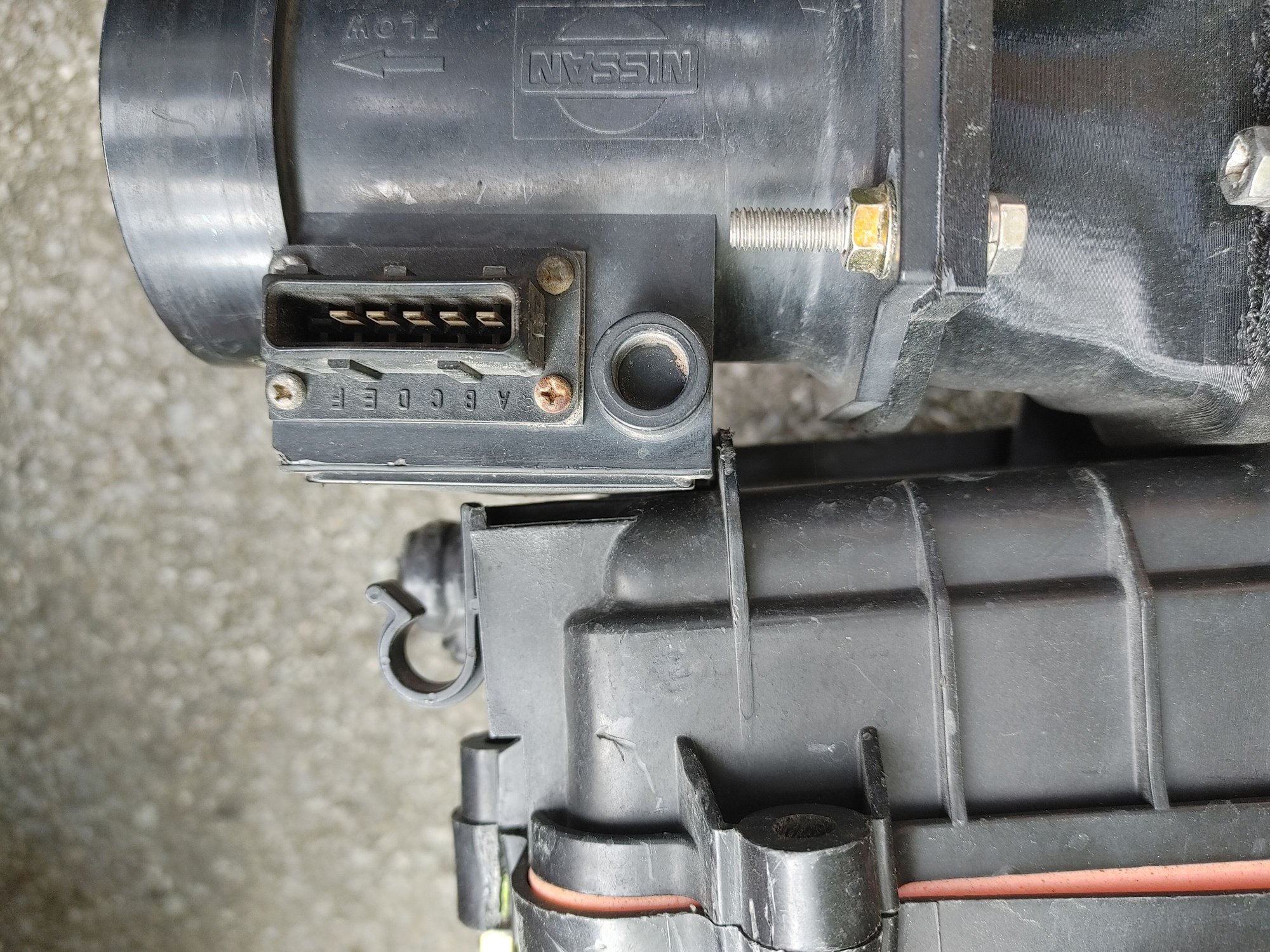
The actuator looks like this (on S4 models):


The little tube to the left is a pickup that connects to the exhaust. As you cross about 4000rpm, the back-pressure in the exhaust drives these actuators and the ports start to open up. This presents an obvious problem with an aftermarket exhaust - where do you get this pressure from? Most exhausts don't have the pickup for the tube, and even if you wanted to add a tube the aftermarket exhaust probably won't have as much back-pressure. There are a few solutions I've heard of (and tried):

- Use air from the air pump (with or without an RPM switch)
- Use an electric air pump and an RPM switch
- I've read of at least one person saying they used cable actuation connected to the throttle (for which I can no longer find the post)

There are problems with all of the above:

- The air pump builds pressure way too early (2000rpm) which means the ports are opening about 2500rpm earlier than they should
- Most electric air pumps are an impeller style. After testing, I was not able to find any that build enough pressure at the outlet to budge the actuators at all. I've read of people using an aquarium pump, but I have my doubts about that pump surviving a long time under the hood of a car
- Even if you did get either of the above to work, an RPM switch is the wrong approach. We want to actuate the ports based on load (in my case MAF), not RPM. At light load above 4000 rpm the ports being open is worse than them being closed. Now I know that light load above 4k is not a common situation, but my point stands.
- A throttle cable has a similar problem, which is that now it's tied to throttle-position instead of MAF. If you floor the throttle from idle, even before you leave idle the ports are already all the way open.

I experimented awhile ago (see page 8) with using air pumps, MAC valves driven via PWM, etc to try and have the ECU control the ports based on MAF. But there wasn't any solution that I was happy with.

Recently I decided to pick this project back up. Here were my goals:

1. The ports should open at the appropriate time, consistently (I could never get this to happen with the air pump options).
2. I should be able to control them with the ECU, and adjust the opening time.
3. They should be controllable based on MAF
4. The solution should be reliable
5. (Nice to have, but not 100% required) I should have infinite control over the port position, not just simple open / closed control.

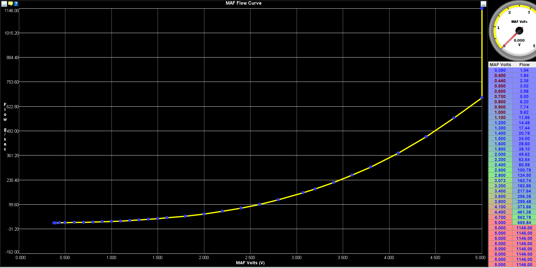
Why did I want number 5? Well, one thing I noticed when testing with the air pump and a MAC valve is that it's not difficult to get the ports to open, but it's difficult to get them to stay part of the way open. I wanted a way to have the ports not just be open or closed (40 degrees vs. 80 degrees closing time) but to be able to hold them at say 60 degrees closing time. This would maximize the area under the curve in the powerband. Speaking of which, here is some data I took from a log:


It's a bit crude since I'm using MAF as a proxy for power, but since I don't have a dyno this will have to do. The first thing to notice is that the closed ports flow a lot more until about 4250 rpm, and then the gap starts to narrow. At about 5250 rpm the open ports surpass the closed ports in terms of airflow, and after that there's no contest. I think the weird dip at 6250rpm was tune related, but this was several months ago so I don't recall the exact cause.

Anyways, this begs the question - if 80 degrees close time is flowing more at 5250 rpm than 40 degrees close time, is 50 degrees close-time outflowing both 40 and 80 at 5250 rpm? Ideally, I should be able to start opening the ports at around 4250 rpm and open them smoothly until they reach full open at say 5750 or 6000 rpm. More testing would be required to determine the exact transition points.

I'd seen a photo online of someone using solenoids to pull the ports open, but I originally scrapped that idea for a few reasons. Mostly that it required mounting some return springs (with no good OEM location to mount them to) and also that I was concerned with reliability because of the short duty cycle and the fact that the solenoids would sit above the exhaust manifold.

But then I saw these on Amazon and I did some more thinking:


They have an integrated return spring, so that simplifies the bracketry. They have 60N of force which should be much more than required to open the ports. They fit in the available space, and they also had a clevis that looked like it might fit the stock linkages. And at 3A each, they could hypothetically be PWM driven by my Megasquirt. So I ordered a set for about $40 and did some testing:


The first thing I tried was powering it for awhile and seeing how hot it got. The answer is "not very". It has more than enough strength to pull the ports open, and the "3 seconds 80 degrees temperature rise" in the description didn't seem to occur. It definitely got warm, but not that hot (even after 10 seconds). I didn't end up pushing it because at some point I would burn out the solenoid. Even with the added exhaust heat I'm confident that these will last a good long while. Besides, how often am I above 6000 rpm with the pedal flat-out for more than a few seconds? Every time I shift it will drop back down below the threshold anyways.

Worst case scenario, these are pretty cheap. I can always replace it if I burn one out.

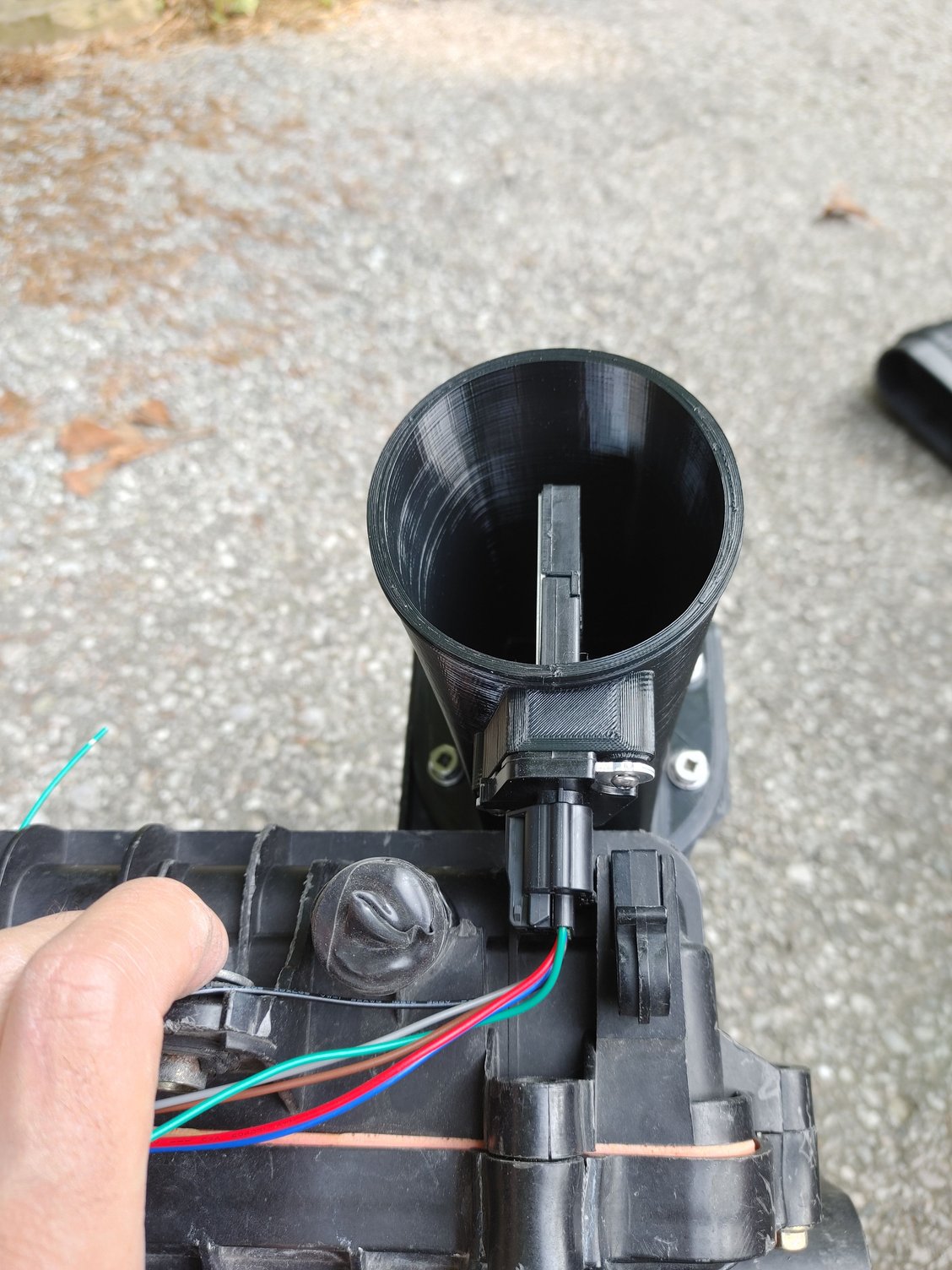
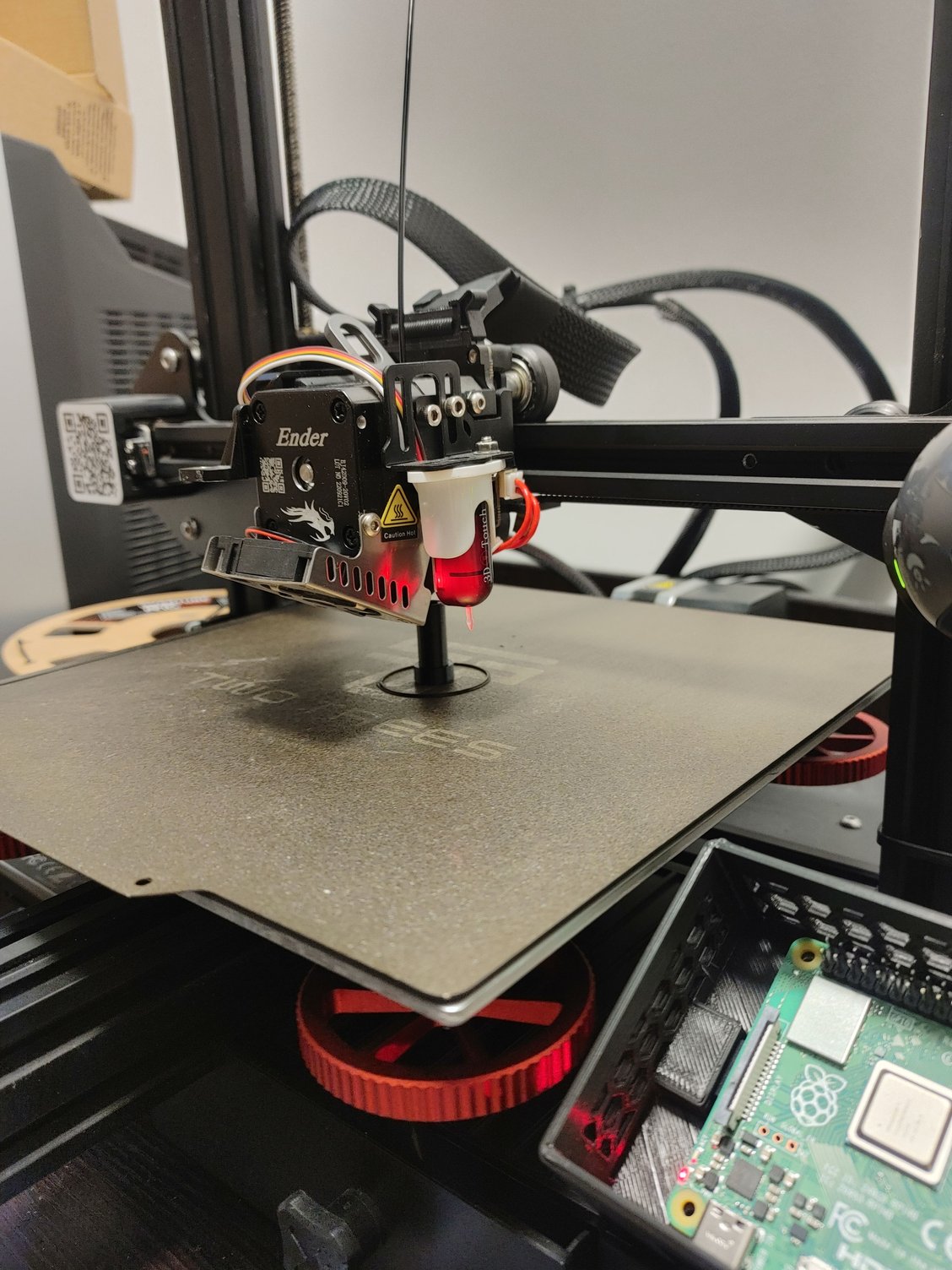
You can also see the mounting plate and linkage. That linkage is for testing only, since I was in the middle of fixing my 3D printer at the time. The linkage is required not only because of the fact the sleeve is rotating, but also because the actuator is positioned somewhere in the center of this rotation. So when the actuator starts moving the linkage ends up pivoting from one side to the other. I'm probably not describing that well, but suffice it to say the linkage is required. Here is a mock-up with a drill bit since I didn't have an appropriately sized screw and some M8 nuts used as washers:


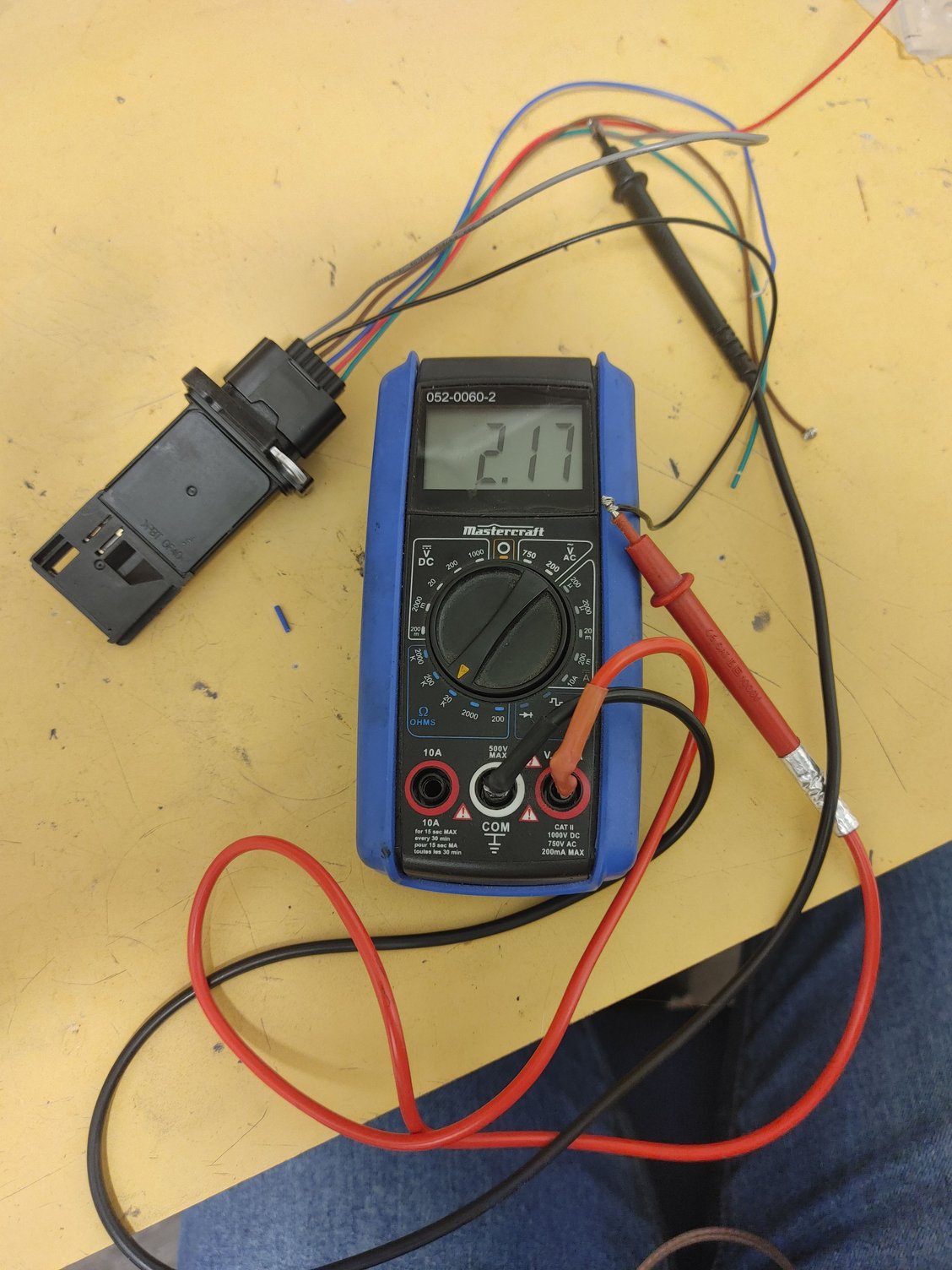
I tested it and confirmed that it absolutely had enough power to pull the ports open. The return spring was a bit too weak, so I removed the circlip and stretched it taller before putting it back and that fixed the issue.

Now I mentioned wanting to have infinite control of the position of the ports, so I rigged up a simple system to PWM the solenoids with a microcontroller and see what PWM duty corresponded to what port position. But I noticed something interesting which is that any duty sufficient to move the solenoid would open the ports all the way. I could slow the opening a bit but I couldn't halt it at say 50% open. I realized there was something I hadn't considered with the solenoids, which is that the power required to pull them inwards decreases as the rod enters the coil. This makes perfect sense and I'm not sure why I didn't think of it before. It's possible there is some sort of solution involving a progressive spring for the shaft that increases spring tension as the shaft moves inwards, but for now I'll have to shelve that particular goal.

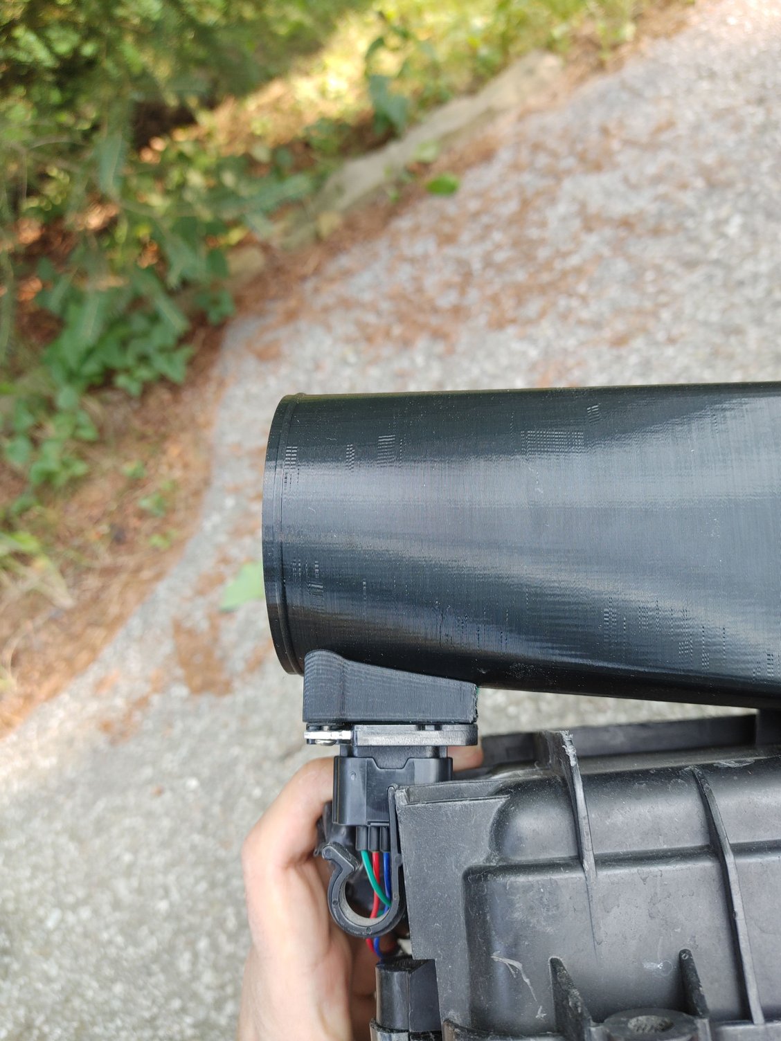
I also noticed something interesting, which is that the stock actuators don't open the ports all the way. Before the actuator rod hits the inner stop, the actuator itself runs out of travel. You can see how far they open in the second photo of this post. Meanwhile the solenoids have travel to spare, so the actuator rod hits the inner stop and the sleeve opens further:


This is about 2-3mm more open than stock. I could probably get it to open further by filing down the inner stop. That will be a project for another day.

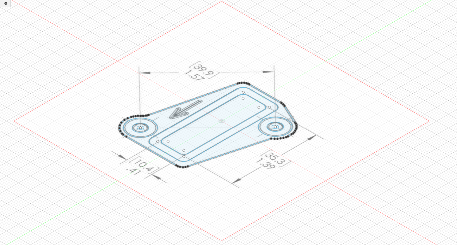
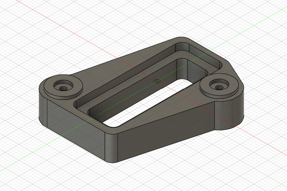
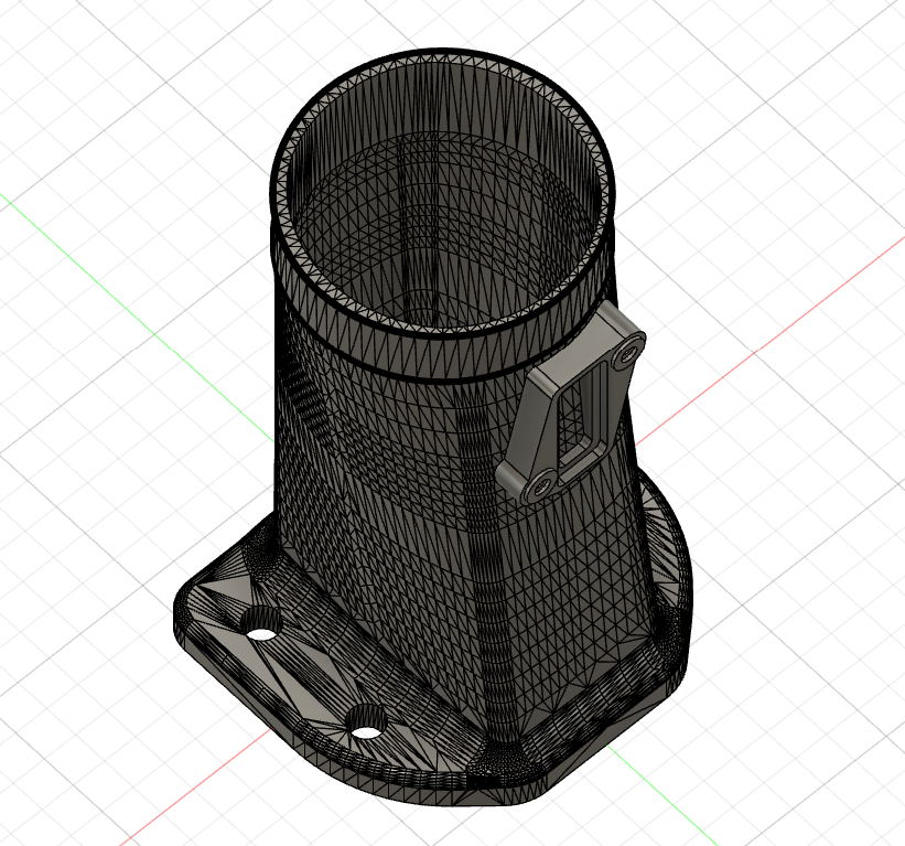
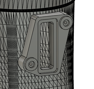
With my 3D printer fixed I made a replacement for the linkage:


In testing I found that flat linkages tended to try and slip off the actuator rod pawl if the solenoid shaft rotated a bit in either direction. So this design fits neatly into the solenoid clevis and has about 10mm of sleeve engagement on the actuator shaft. With some silicone grease everything is nice and smooth.

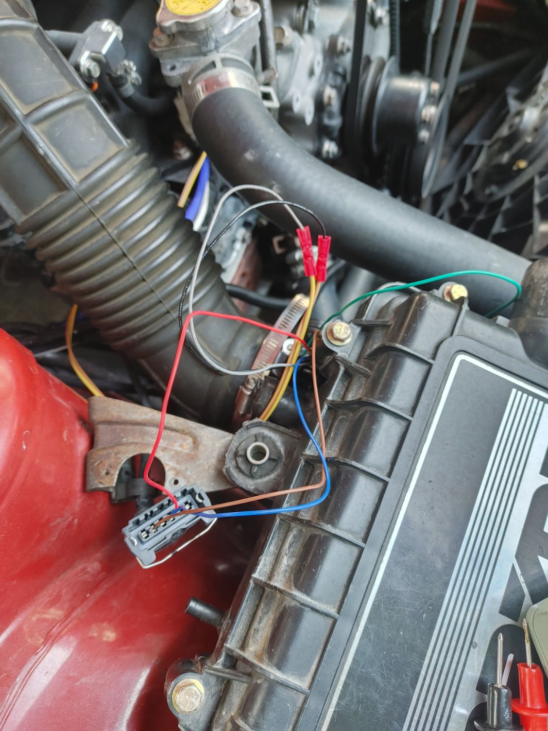
Since PWM won't help me on this project, I elected to run a relay so there is less load on the Megasquirt. It mounts to the passenger shock tower. Here's some night photography of the solenoids installed:


I still need to loom up the wiring, but otherwise it's done.

And the results? Well, it works. I can use the Megasquirt to open and close the ports when I want, and there is a way to reference it to MAF so it will do what I need. They also open slowly enough that I think if I start opening them at 100 g/sec of airflow they will take enough time to open that it smooths the transition and (mostly) achieves the effect I was looking for regarding infinite control. It's not as good as real infinite control, but it's what I have for now.

Idle and off-idle is also noticeably better with these ports open. Once the weather warms up enough for me to actually drive the car, I'll report back with the results vis-a-vis power and in the summer I'll have to test them on a hot day to see what reliability is like. Fingers-crossed that this pans out and I don't need to go back to the drawing board, because at some point it just makes more sense to focus that effort on swapping in the Turbo II engine I've been sitting on for three years.

Until next time

WondrousBread
WondrousBread Reader
2/16/25 6:04 p.m.

We've been receiving lots of snow recently, so I went looking for a project I could work on inside. Recently JP3 motorsports has made their AC retrofit kit available, and while I won't be purchasing it anytime soon due to the current exchange rate, it is something I'd like to pick up in the future. They released a very helpful video showing how to remove the evaporator assembly and replace the expansion valve. I figured that this was a good idea, since the air in my car has never blown very strong and there was more than likely some obstruction in the system from leaves and dirt. The lack of fresh-air filter on these cars has always frustrated me a bit, so while I was in there I went looking for a way to add a filter to the system.

It starts with removing the clamps that hold the inlet and outlet of the evaporator assembly:


And immediately I noticed that the evaporator outlet wasn't even clamped on. I wonder why the air has never blown properly in this car...

I have had the dash out before and didn't notice this, but then I didn't really pay any attention to the HVAC system at the time. Oh well.

The inlet side (coming from the blower assembly) has a screw clamp instead of a flip handle:


Then there are two nuts on top:


One on bottom:


And then the box comes out. I actually forgot to take a picture before I disassembled it. It's just a grey box with two openings and the fittings for the evaporator core extending out the front.

These little spring clamps hold the box together, so they just pop off:


From there the box comes apart into two halves:


With styrofoam inside both halves surrounding the core:


As you can see, there was quite a bit of yard waste in there. The core itself was not that dirty, but it did have a lot of old tape decomposing on it:


After vacuuming and cleaning everything in the sink, I dried it with a heater:


And then with the evaporator as hot as I could possibly get it, I propped it over the garbage bin for awhile to get any remaining oil to drain out:

WondrousBread
WondrousBread Reader
2/16/25 6:04 p.m.

Now one thing that I realized immediately when starting this project was that all the foam in this system needed to be replaced. It had long since turned to dust. I started with removing the blower motor, since it makes the whole blower assembly a bit lighter and easier to maneuver out from under the car:


Yikes. It's been pretty squeaky since I purchased the car, and now I know why. I thought that servicing the bearing might have been an option, but then the carriage bolts started spinning when I tried to disassemble it. Add to that the state of the brushes visible through the vent hole, and I decided to just order a replacement.

This is the blower assembly itself:


That flapper door controls whether the air is in recirc mode or fresh air mode. As you can see, the foam is dusty and the door is covered in rust. The inner door is also rusted in the open position:


At least the wiring is still decent. For an idea of how crusty the foam is, look at what happens when I touch it:


It just turns into a fine dust and falls right off. This project won't be done until spring purely because I now realize I need to replace ALL of the foam, including the heater box and all of the vents. That can't happen easily with the dash installed, and the dash can't safely come out when it's this cold or half the fasteners will break.


The box is held together with the same spring clips as the evaporator box, so with those released we find another rusty plate and some large electronic component with an aluminum heatsink:


This rusty packing plate is on the other side of the blower resistor:


And then the aluminum thing is held on with two fasteners on the back of the box. This side faces the firewall, so if you're thinking of tackling this project yourself then remember to plug this back in before reinstalling the box:


This actuator on the side handles the flapper door:


From the inside you can see how rusty the door was, and the little flapper door on the larger flapper door (flapper door ^2) is rusted in the open position:


This means even on recirc there would have been outside air entering the cabin.
 

WondrousBread
WondrousBread Reader
2/16/25 6:05 p.m.

I was able to get the flapper doors out:


The rusty fasteners presented a bit of a challenge, but they all came out except for one on the smaller door hinge. The head snapped off, so I had to heat it and oil it several times before welding on a new head:


Fortunately that was enough to free it and I went and cleaned all the rust off:


I used gel rust remover, followed by POR Metal Ready to etch the metal. I think the Metal Ready leaves some sort of protective coating so it might actually have been fine to leave it at that, but I decided to paint it just to be safe.

After shooting some VHT Chassis / Roll bar paint, I began adding new foam:


It took some experimentation to find the right foam height, but I got it pretty close. I found there was quite a bit of slack in the door, probably caused by this plastic piece being worn out:


It wouldn't be hard to print another one, but I'm going to test with the original piece first and see what happens. This part is easily accessible with the box installed, so I can always replace it in the future. At its current resting position the door doesn't sit all the way closed:


Once I reinstall the box in the car I'll cycle the controls and see if it still rests here.

Then I reassembled the rest of the box:

WondrousBread
WondrousBread Reader
2/16/25 6:05 p.m.


That was by far the rustiest piece, so I'm glad it turned out okay without too much missing material.

I took the rubber boots off of the relays to clean them:


It doesn't really matter, but everything was grimy from almost 40 years worth of foam dust and dirt from the lack of filter. Plus me always having the windows down and sunroof open due to the heat in the summer certainly doesn't help the matter. A little bit of extra time cleaning everything is well worth it.

The blower motor resistor seems to have melted long ago:


I've always thought the fan was weak on settings other than high. Also on high. Speaking of which, here's the new blower motor:


This is the Four Seasons aftermarket part. I've heard that it's a pretty good fit but blows harder than the original, and with it in-hand it feels like a quality part. I cleaned the fan itself and installed it:


Then the motor and fan fit into the assembly. The Four Seasons part is a bit taller than OEM, and the plastic cover is a bit too short to fit properly:


But at the end of the day, it does bolt on. You can also see I removed the old harness tape and replaced with the fabric anti-rattle stuff I've become a fan of in recent years. It's a small thing, but it helps. The connector for the fan was cut by the previous owner, not me, so when I'm done testing I'll replace it with the correct OEM connector.

Speaking of testing, I've been playing around with a solution for the cabin filter which I'll go into in my next post.

WondrousBread
WondrousBread Reader
2/16/25 6:05 p.m.

I'm sure every other Rx7 owner has had the same irritating experience - you're behind a truck on a dusty day, you enter their dust cloud, and the dust shoots out all of the vents into your eyes, nose, and mouth. It only has to happen once before you learn to quickly hit recirc and close the fresh air vents the moment there is dust in the air.

The solution is a cabin-air filter, but the challenge is finding a place to put one. I had some ideas about installing one under the wiper cowl, but then I really need to worry about it getting soaked with water. Inside the cabin is a better option, but there obviously isn't a convenient place for it. So I found the least inconvenient place for it - the inlet of the blower assembly. Replacement would be about an hour's work, but for the amount of mileage I put on my Rx7 that would still only be every few years.

I started by designing a simple filter basket and printing it out of flexible TPU:


I purchased a cheap cabin-air filter and drew some measurements on it, then took it apart to start constructing a custom one:


I wasn't sure what the correct adhesive was, but the filter was originally assembled with hot-glue so I went with that. It's a bit ugly and the seal isn't perfect, but it's good enough to test and see if this concept will work.

I hooked it up to this jump pack and tested to see how much restriction it added:


For my first (non-scientific) test I simply ran the blower motor with my hand in front of the outlet, then installed the filter to feel the difference. Unfortunately, it seems to be a pretty significant restriction. Then I used an anemometer to measure the actual airflow; without a filter it's about 7.2 and with the filter it's under 5. I don't recall the units offhand but for this comparison the units are arbitrary. Clearly the filter means there will be a pretty big compromise for airflow.

For additional evidence, installing the filter makes the little bypass door open as well:


So I'm going to have to do more thinking on this one. There is no extra vertical space to utilize because it will start to interfere with the flapper door on the bottom and the fresh-air vent inlet on the top. For anyone without a similarly equipped car, Canadian cars came with a slider on either side of the dash that pulls a flapper door inside the dash. This door will cut off the door vents from the HVAC system and instead just direct air from the cowl straight through the vents, so it provides ventilation with no noise or electricity required. It's a pretty cool feature, but it does mean I need to find a way to work a second filter into the system as it uses it's own air supply.

That's where I'm leaving it for now. The heater box is next, but that will have to wait for warmer weather. Until next time

WondrousBread
WondrousBread Reader
5/1/25 6:05 p.m.

There are a few updates that have happened (lots of pictures, not a ton of material progress). I'll be dividing it into a few posts.

I wanted to redo my ECU mounting bracket. My MS3X was previously mounted using this plate:


It's not blurry in real life, I swear!


The zip-ties were a temporary mounting solution while I was testing something - the ECU was securely mounted using those screw holes for the last several years. You might also notice the 3D printed Megasquirt case. This was an effort to address my main problem with this bracket; the Megasquirt is significantly taller than the stock ECU, and the kick plate that goes between the ECU and the carpet wouldn't fit properly.

This plate mounts to the stock ECU bracket, and I'd read that the MS3X would fit under the stock kick plate if mounted towards the top of the bracket. However, in my testing I was never able to get it to clear with the stock case. I did however realize that there was space underneath the stock bracket that couldn't be properly utilized with a simple flat plate, so I was determined to change that.

Step one was to snap the spot welds holding this vertical bar to top and bottom bracket pieces:


Step two was to get an appropriate piece of steel:


And bend it up:


I'd like to provide progress pictures of the bending, but I didn't take them. Essentially I took the end length of the bracket, added in about 10mm (*2) for the extra length of the walls of the inset, and then bent it in a metal brake. Unfortunately the brake I have was only able to do 2 of the 4 bends since the walls of the inset are so short that they don't reach the edge of the brake. I made the remaining bends carefully by hand, which is why they look a little wonky:


But they serve the purpose:


I wanted to keep the bottom piece of the bracket, even though not strictly necessary. It has a 10mm stud on one side that may prove useful as a hold-down later on. However, these spot-welded cable guide have to go since they interfere with the mounting plate:


I removed the rust via electrolysis, and then hit it with VHT chassis paint. Speaking of which, that's what I also used for the bracket:

Now regarding the custom MS3X case, I didn't actually end up using it. I got pretty close to a final design:


It works, and I even used aluminum tape on the inside to make sure it was still RF shielded. But the extra clearance gained with the new bracket is enough that I no longer need the slim case, so I just ended up using the stock case instead. The kick plate fits flush though:


I also decided I didn't like the USB cable I was using for tuning. It was very long which contributed to the messy wiring near the ECU, and I had it run under the dash coming out near the passenger seat belt. It worked fine, but I wanted to tuck it somewhere that is entirely invisible when not being actively used. So I bought a 1ft bulkhead-mount USB B cable online and mounted it to the top of the kick plate:


This sits way up against the firewall. I have another 1.5ft extension (for some reason they only came in packs of two?) which will plug into this one and mount to the bottom of the dash plate where the stock alarm lives. This way I can just plug a USB B cable into the connector when I want to tune, and then when I don't want to tune the car appears completely stock.

Now the next step was going to be replacing the EFI harness with a new custom one, but I wanted to deal with the heater control box so I didn't have too many projects on the go at once.


The last part of the HVAC system to need resealing was the heater box. It lives directly behind the center vents and radio in the dashboard. It might technically be possible to remove it without removing the dash, but I think it would be cumbersome enough that removing the dash is an easier proposition:


It really only takes like an hour once you know where all the fasteners are. Ignore the messy wiring for now - we'll deal with that later on. Here's the item of interest:


Those vents to either side just pop out with those little push fasteners removed. Then the entire thing is held in by four 10mm nuts.

I took the box to the basement and started inspecting it. It's neat how this works:


There is a little valve to cut off coolant flow to the heater core when you have the air on cold. I think some cars only have the flapper door, so it's neat that Mazda added this valve to prevent heat excess heat entering the cabin on a hot day even if the core isn't receiving airflow. Not that the cabin doesn't still get super hot the moment the sun is out, but hey, any improvement is appreciated.

As you can tell the vent foam is pretty crumbly:


I gave all of the doors the same treatment as the ones in the blower motor box - strip to bare metal, paint (more VHT chassis paint), new foam:


I had been using double thickness closed-cell foam to try and get a better seal, but I realized it wasn't compressible enough and was leaving a gap at the edge of the door furthest from the hinge. So I stripped off one layer of the foam and added a softer open-cell foam instead:


That resulted in a good seal.

Speaking of good seals, I had a persistent leak from the driver's side heater hose whenever I drove the car hard. I think it was a combination of the extra heat and pressure from high RPM operation, plus deformation of the soft brass tube. I had an idea to strengthen it using an inner sleeve made out of a tougher material. Enter some 5/8" OD stainless steel tube:


I sanded down the OD of the tube just enough for it to fit into the brass heater tube, then rammed it in (being careful not to bend the brass tube any further). Once I felt like I had enough length in the steel tube, I measured how far it fit inside the brass tube and cut out that section:


Then tapped it home:


Now when I tighten the clamp, it should apply pressure against the inner tube rather than deforming the outer one. It might restrict flow by a little bit, but I'm not too worried about that in practice.

I also cleaned every part of the heater box before reassembling of course. I added grease on any moving part. This is more important on the sliding linkages, but I also felt like adding some on the rotating bushings couldn't hurt:


I actually ended up re-using the stock hoses and clamps that connect the heater core to the tubes that go through the firewall. I had purchased some new tubing and clamps, but the old ones still felt quite soft and looked to be sealing perfectly. Also, the new one wasn't as tight a fit and I was concerned that I would have to tighten the clamps extra hard to compensate.


At that point the heater box was ready to go back in the car, but bigger concerns have arisen.

WondrousBread
WondrousBread Reader
5/1/25 6:07 p.m.

I resumed taking apart the rest of the parts on the firewall that aren't normally accessible. These small tubes for the fresh-air intake aren't normally accessible with the dash in place, so they're a good candidate for cleaning while I'm in here:


I also removed all of the little brackets for cleaning, as well as the wiring. One of the three stock ECU connectors is for the body harness, and my plans include keeping this particular harness. So I removed any loose electrical tape that had gotten greasy and then wound it in Tesa interior tape:


There was also the matter of this thick insulator mat that sits against the firewall:


It's a jute type padding with a rubber backing. Unfortunately the jute material was so old and deteriorated that just touching it made it turn into dust and blow away, so I figured I would remove the mat and replace the jute with something else. I also noticed that someone has been in here before, since the mat was folded and pinned under this harness:


Is there even one part of this car the previous owner didn't mess with?

Anyways, the pedal box had to come out and the steering column had to drop:


Sorry it's underexposed - my camera has a thumb adjustment for exposure and when taking photos outside it's very easy to bump the adjustment and not notice since it's so bright out.

And then I found this:


Yikes. No holes, but still, pretty bad. At this point I decided to do some investigating (which is never a good idea)

It didn't take long to figure out where the water was getting in:


This is the upper left corner underneath the wiper cowl. Water was leaking in there and just soaking the back of the mat. It was most likely sitting against the firewall in that jute for weeks without drying.

It was also leaking down onto the floor:


Some of it in behind the fusebox area:


This was enough to tell me I should remove the carpet and find out just how far the water had crept:


It was pooling in a couple of places, but it seems to have made it's way all the way to the hatch release lever.


I also started thinking that it would be a good idea to inspect all the prior repairs. Particularly since some of them were from before I bought the car, some by my dad, and some from me. And I can guarantee that no one who has worked on this car in the past (including myself in several instances) did body repair correctly.

With my Rx7 about to turn 40 this October, it's now an old enough car to just go big or go home. Ignoring floor rust now just means more work later, and clean shells are no longer common or cheap. When I first restored the car a few years back, I inspected all the repairs and found no rust. Then I made sure everything was painted and added some sound-deadening. My standards for what constitutes an acceptable repair have shifted since then.

I first peeled up the CLD that I added myself, as well as some of the closed-cell foam padding I was using under the front of the carpets. Then I took a dead-blow hammer and a chisel and started going medieval on the OEM stuff underneath:


After about 6-8 hours of chipping:


Interestingly, there were several places where I found water under the OEM insulation. I think this stuff is a bit porous and/or has separated a bit from the substrate and allowed water to seep underneath. It also might be a cyclical problem - rust causes insulation to lift a bit, creating a small gap, allowing water to seep in, promoting more rust.

I've heard people use dry ice for this, but actually getting dry ice would have required a drive to the city as well as taking a day off work. So I did it the old fashioned way. The remnants still need to be cleaned up, but it's now clean enough to see what we're dealing with.

Starting at the front of the driver's side, there's rust in the top left of this photo. Not sure whether it's penetrated the metal, but it looks deep enough that cutting is the only correct repair. I also see rust on the floor that the frame rail butts up against, and rust inside the frame rail itself through this access panel:


My frame rails aren't crumbling or anything, but it will get bad soon if not addressed. I already have bolt-in rail reinforcements (the bolts in this photos) but that is no excuse to let the rail itself rot away. You can also see how wet the floor was - those fasteners used to be gold, and now they look like they belong on the titanic.

There's rust under the seat mount, which means I'll need to remove it to replace the sheet metal:


Also a prior repair at the rear seat mount. I remember we had a local guy do these repairs for us when I first purchased the car. The repair itself isn't bad, but it wasn't coated very well and the welds are rusty. So is the floor behind the repaired area. This implies to me it should've been cut further back, but I'm pretty sure the guy only charged me $120 for a few hours of work so I can't really be that upset.


The seat mount itself isn't terrible, although it is bent a bit from repeated use of the frame rail as a jacking point:


Then at the passenger front we have this lovely repair. This is actually one of mine:


I think I was trying to repair the double-walled section of the floor at the front, and for some reason I just replaced the outer panel and not the inner. I mean, it works. But if water were to drain into this area then it would just pool there forever. I don't actually think any water was finding it's way here but the sheet metal started to rust on top nonetheless. Add to that some pinholes near the mounting stud for the ECU panel and this entire area will need to be addressed.

The passenger side rear seat mount has been repaired by seemingly riveting some sheet metal over the holes.


From underneath I don't feel a seam anywhere, so I suspect that removing that plate would reveal several smaller holes that were just plated over. This is one of my dads. I love my dad and he's a talented guy, but neither of us have ever been naturally talented at bodywork. Also, I bought this car for $1600. I'm pretty sure he was more concerned with just making sure it was safe and not particularly worried about what the market for clean Rx7s would look like in 8 years.

Here's all the insulation I chipped out:


If you're wondering how much it weighs, wonder no more! It's 28.5 lbs. That's the entire floor area and firewall. Consider that 15 lbs or so is probably insulation I added myself, and the weight gains from removing insulation are pretty slim. Also consider that if you bang on the floor with a hammer the car now resonates like a drum. Unless you're building a race car, you really should leave the floor insulation in place.

And I fully intend to put fresh insulation down, but first I need to figure out how to deal with the floor. I'm no stranger to cutting and welding, but the rust at some of the seams is my main concern. I'm thinking the correct repair might actually be to drill out the spot welds and remove the entire floor pan. That will give me access to the frame rails as well as the ability to replace any of the metal along the seams not easily done inside the car. That does however mean removal of the transmission. I also need to fix the ol' wide-bondo on the driver's side rear quarter, the bubbles on the passenger side quarter, the little panel at the bottom of the passenger quarter where water collects when the drain tube for the hatch isn't pushed through, etc. At this point I'm seriously considering making a simple rotisserie and just going all in.

I'd really like to drive my car this summer, but that probably isn't in the cards at this rate. I'll still be doing everything in my power to make it so. I can't do any more work until I have some proper garage space, and there's a Miata with a disassembled timing assembly in the way right now.

There's more rust than I'd hoped, but actually less than I expected. Overall I'm not too upset by it. It's still a lot cleaner than most of the FCs I've seen for sale lately.


Until next time

WondrousBread
WondrousBread Reader
5/3/25 10:20 a.m.

I spent a good amount of time thinking about how to build a good rotisserie. It looks like commercial units start at $2k before shipping, and that's for pretty basic units. I also think that (from the pictures I saw) the quality of some of those cheaper units is a bit suspect.

The engine stand option would have worked, but it has a few disadvantages:

- Most stands have the engine angled slightly upward, requiring me to cut the main upright to angle the cylinder horizontally
- Most cheap stands aren't that strong, requiring reinforcement before I'd be comfortable using them to hold up a car
- They aren't tied together, so moving the car would be a bit sketchy
- Limited adjustability
- Still requires building the mounts for the frame rails, as well as a vertical drop from the center of the rotating cylinder to allow for centering of the vehicle.

I also considered building a set from scratch, but then once I added up the cost of steel it was going to be at least $800 - $1000 for a set with no adjustability. That means that if I get the measurements wrong and the car isn't centered, cutting and welding would be required to compensate. Also, a fixed-height makes it difficult to raise the car up enough to bolt it to the rotisserie.

So just for the hell of it I put "car rotisserie" into Kijiji, and what do you know:


This was for sale about 45 minutes away from me. It's a homemade unit but it's super solid. 2.5" square tubing, 3/16" thickness. The previous owner built it specifically because he looked at the commercial units and found that they lacked adjustment and they all needed to be modified anyways. His friend did the welds (which are super solid) and there's even a long square tube (right hand side of the photo) to tie the ends together once assembled.


It's height adjustable on both sides. So you can get the car centered relative to the rotating shaft (which is important, otherwise the car will try to roll in place) and then still adjust it up or down from the outside with it remaining centered. The attachment points are adjustable for different widths of car. The only thing I don't like is that the casters don't lock, but that's easily fixed by just replacing them.

I also got two bottle jacks from the previous owner which will fit on each stand. I can add a little platform just below the outer cylinder on the rotating joint, and add a piece of tube to the joint against which the jack can push. That lets me adjust the height easily even with the car on it.

Also, it was about half of what it would cost for me to buy the materials to make a non-adjustable rotisserie. I still need to buy the steel to build the attachment points for the frame rails, but overall this feels like a pretty good deal and I think it will work for my needs.

amg_rx7 (Forum Supporter)
amg_rx7 (Forum Supporter) UltraDork
5/3/25 2:02 p.m.

In reply to WondrousBread :

Bummer about the rust. Keep up the good work though. Enjoying following along. 

WondrousBread
WondrousBread Reader
5/5/25 1:20 p.m.

In reply to amg_rx7 (Forum Supporter) :

It's a bit of a bummer, but honestly I expected worse. I've kind of had the old floor repairs in the back of my mind for a little while now, and the firewall rust finally forced me to take another look at the floor. 

This is a good opportunity for me to give the chassis a complete inspection and repair. Plus add some mounting points for later bolt-on bracing that has been in the back of my mind for awhile.

Dusterbd13
Dusterbd13 MegaDork
5/17/25 4:41 p.m.

Man, dunno how i haven't read this thread. 

What exactly did you use on the blend doors for foam? I need to do my truck and miata. 

WondrousBread
WondrousBread Reader
5/21/25 6:50 p.m.

This weekend was a long weekend here in Canada, so I spent some time on Monday continuing to strip down the car. First though, I had to put the steering column back in so I could actually steer the thing:


Securely mounted. That's over 5 zip-ties right there!

Incidentally, you can see in this photo that I've completely cleaned the floor area of residual sound deadening. I've also chipped away all the deadening in the rear. The firewall still needs some work and then everything will get one more pass with enamel thinner to get any residue.

I hopped into the car to steer while my brother pushed the car into the garage:


Then we removed the hood and put it on the roof, since I will need to shuffle some other things around to make space. I'm slowly packing car parts into every storage space I have available.

I don't have an engine crane, but I do have one of these:


It's tethered to a big steel I-Beam that crosses the length of our garage. A bit fiddlier than an engine crane since there's no way to level it and you have to move the car out from under it before lowering, but it works.

Removing the engines on these cars is pretty easy if you've done it at least once. The engine harness was already disconnected from the inside, so I just made sure to unplug all the connectors and then pulled it with the engine:


It probably took a little over two hours. I do wish I'd been a bit more careful on the driver's side - the throttle cable snagged on something while I was raising the engine and was damaged, as well as the long starter bolt (visibly bent in this photo). The starter bolt in particular bothers me, since it could potentially have snapped the iron on the engine. Fortunately the only damage was to the bolt itself.

After that I drained the transmission. The fluid looked a bit weird:


The fluid I put in was regular brown synthetic gear oil, but the stuff that came out had this weird radioactive blue film. It was actually rather neat to look at:


Not quite sure what causes that. The Royal Purple that was in the differential came out looking exactly how it went in.

Removing the transmission on these cars is also easy - made even easier with the Cusco under-brace that gives it something to rest on when there's no engine installed. The NA transmissions are really light so I typically just grab the transmission and remove it without a jack (NOT that I advise doing that).


There was definitely an oil leak at the rear cooler line - not sure if from the line itself, the fitting, or the crush washer.

WondrousBread
WondrousBread Reader
5/21/25 6:51 p.m.

The car was just high enough in the air for me to remove the transmission from the side. It's actually a lot scarier with the engine out. Small bumps to the chassis are a lot more likely to knock the car off the stands than with the engine installed.


Drained the fuel while I was in the area:


It's advantageous to drain it well in advance of actually removing it, since that gives the residue time to evaporate. Working on the car was a little nerve-wracking with the engine suspended in the air:


I know it's on there securely, but even so.

The only cart I have available is this little guy:


I've actually had more than one 13B on this stand. It may be small, but 13Bs are light and fit on it pretty well. It's bigger brother currently has a 13BT on it.

Rolled the car straight back out so there was space to lower the engine:


With the oil pan and pickup removed, 13Bs are pretty much flat. I think the oil pressure regulator protrudes slightly but it fits into the void in the center of the stand.


That's it for now. There's still a lot to do, but frankly these cars are like LEGO bricks once you've spent some time on them. Very easy to take apart and put back together. The same probably can't be said for the actual bodywork ahead of me, but I'm just going to take my time and I think it'll be fine.

Until next time

WondrousBread
WondrousBread Reader
6/1/25 9:22 p.m.

I've been slowly picking away at emptying out the engine bay. I still have some minor cleanup of the interior floor, but it's largely bare. Other than the headliner and sunroof panel every interior part is stowed away in my basement.

I ran all of the fasteners through the ultrasonic cleaners for a few baths and then chased all the threads with a thread cleaner:


Many of them are common fasteners that are easily replaced, so they won't be reused. I'll keep them aside for something else and just replace with new. But that's no reason to put them away dirty.

After that I started removing piece after piece. The following pictures aren't that interesting - just photos of things that are to be unbolted and packed away. But they will serve as convenient documentation when I put it all back together later.


This is a custom fuse panel I made a few years back for high-current items (e-fan on one circuit, alternator on the other). It worked fine but it looks very messy. I'll keep it for now but I doubt it's going back on the car.


The fuse panel has some convenient plugs on the bottom, then two 10mm nuts hold the original main alternator wire on and it just pops right off.


The body harness runs along the front bar and then to the area under the stock airbox. There's also the power steering cooler loop and the oil cooler (already removed in this photo).


Under the custom brake hoses for my Subaru brake booster / MC are the disconnects for the transmission / starter / charging system sub-harness:


It was a bit greasy from the oil that had been leaking from the rear oil-cooler, but overall not in bad shape. If the oil has wicked into the wiring I might just replace the affected wires. In for a penny, in for a pound at this point.


You have to take out the headlights to unplug them as they aren't part of a sub-harness. Fortunately the connector for the retractor motors is easily reached in the engine bay, so they don't need to be removed (yet).


I found two new areas where rust was starting. One on the front inner fender under the airbox:


One here on the seam of the driver's side shock tower:


Fixing that properly is going to mean drilling out the spot welds and removing the tower, repairing it, and then priming and reassembling. Not too big a deal, but as with every other "little job" they add up.

I put the oil cooler aside, but no matter how much I drained it there is always more oil. I left it like this for 20 minutes with a cloth underneath and nothing happened, and then with zero warning it all leaked out:


Then I spent awhile pushing the body harness through this opening in the firewall. I alternated moving to the interior of the car every few minutes to clear space and make sure nothing was hung up. Eventually it all went through.


Not car related exactly, but our jack has been leaking for some time. This meant that it would lose a few mm a minute in height, and wasn't safe to have any part of your body under the car when it was solely supported by the jack.

Now, one should not be working under a car without properly supporting it on stands in the first place. But one does need to actually put the stands under the car to achieve this so at a certain point the slow-leak becomes a safety issue. My dad found a great deal on a low-profile, high-lift Dewalt unit. Which sounded great until I actually saw the size of the thing:


This thing is huge. Granted, I no longer need to drive my car up onto ramps in order to lift it. But it doesn't help with the space issue now that parts of my car are packed into every available space.

I have spent a long time soaking the fasteners for the front bumper in PB blaster:


Forgive the terrible photo - there is no good way to light the area.

I'm confident that the studs are going to snap off. But these will cost me $125 CAD per side so I'm going to try and save them if possible. Speaking of stuck fasteners:


The little M6 screws that hold the headlight covers on absolutely won't budge. It looks like the last time this car was painted they painted over the threads on the back. This means that not only are they stuck but the PB blaster won't penetrate. I have yet to decide how to deal with these - I'm going to think on it a bit and come back to it later.

The FTP lenses came out with no trouble:


But I am sad to say that my once mint-condition JDM lenses have acquired some small cracks:


Disappointing, but I can live with that.


Took out the radiator and some custom ducts I had made. I'm not sure if I posted about these. They're just designed to seal the rad to the undertray and prevent air escaping underneath the rad end tank.


When taking out the driver's side marker light, I found that someone had spliced a wire in. It went nowhere so I can't really speculate as to what it was for. I swear, there is no part of this car that the previous owner or his mechanics didn't mess with...


There is a plastic bracket thing that mounts to the front bumper cover and then also to the front bar. I'm not sure what it actually does, but the fasteners are really crusty so I'm going to spend awhile soaking them in PB blaster.


At this point the engine bay is mostly clear:


When I posted about the corner at the top of the firewall where the water was entering the cabin, I mentioned that I wasn't entirely sure how to gain access to repair that area. I spent a good long time reading the body manual and inspecting the area, and I concluded that the only good way to repair it is to disassemble the wiper cowl area. That plus some (really minor) rust on the passenger side A-pillar seam necessitates windshield removal.

I'm not too afraid to remove the windshield, but there is always an element of risk to that. My current windshield also has a few stone chips (repaired, but still ugly) as well as a distinct "sand-blasted" appearance. What can I say, ~400,000 km takes it's toll. I decided I'd rather have a new one in-hand just in case.

The Mazda dealership just laughed at me when I asked for the price on a new windshield. He was kind enough to try and source one but confirmed it was NLA. Amayama lists some at about $1000 - $1300 CAD, but there's no guarantee they really exist. Add to that the cost of shipping one from Japan, import fees, residential delivery, and the absurd FedEx import brokerage fees, and I'd probably be looking at $2500 - $3000 all said and done.

I called a local auto glass place and they told me that while they could remove the original windshield there was no guarantee that it wouldn't break. The kind receptionist also spent 20 minutes scouring the country for an available windshield before confirming that no Canadian suppliers had one. She suggested I try U.S suppliers. I asked if she knew any and she simply said "no", so I thanked her anyways for her time.

I google searched and one result came up - Kool Katz Auto Glass. I'd never heard of them and the website is a bit clunky. For example, it doesn't seem to be able to search for a particular car. Instead there's a long dropdown list of tags that you can filter for, or alternatively scroll through 10+ pages of windshields until you find your car.

But they DID have a windshield listed for FCs, and as an added bonus this windshield came without the stupid windshield antenna. As an aside - I know those windshield antennas had their purpose, but in the modern day I find them distracting and ugly. Not just because I rarely use the AM / FM tuner, but also because modern stereos get much better reception than the OEM ones.

Shipping to Canada would have been an additional $400 (USD, not including Fedex Freight's aforementioned fees). My dad has an account with CBI USA in Niagara Falls. This is a business that lets Canadians deliver their packages there for a small fee, and then we can pick it up and bring it home. This way we only need to pay the typical customs fees at the border.

So I shipped the windshield there and we made a 5 hour trip to pick it up:


No picture of the windshield itself, but I did verify that the windshield looked like the correct one and wasn't broken before loading it into the car for the drive home:


It fit into my dad's Acura (but only barely). For any car larger than the Rx7 I think one would need a trailer or to strap it to a roof-rack.

Overall it was a pretty smooth experience. I think we spent less than an hour total in the U.S, and when bringing it back the customs office merely charged me $45 in sales tax and that was that. We left at 7AM and were home by noon.

For now the windshield will live in my shed. I am still going to try and remove the current windshield non-destructively. I might just outsource it to a professional. There are also some spacers underneath it (now NLA) to get the height correct, so I need to save those and make careful note of their position and orientation. The installation will definitely be handled by a professional.

That's it for now. More to come once I free up those bumper fasteners (or lose patience and snap them off) at which point I can remove the subframes and lift the car up onto the rotisserie.

Until next time

DarkMonohue
DarkMonohue UltraDork
6/1/25 10:16 p.m.

Let's see... the usual carefully crafted storytelling, lots of photographic documentation, work progressing nicely...

OOH! INTERCEPTOR!


I do like Interceptors.

WondrousBread
WondrousBread Reader
6/2/25 2:18 p.m.

In reply to DarkMonohue :

Yup, that's my dad's. VF750F.

He got it for like $90 (high mileage, bad paint, cams damaged as usual). He had the cams reconditioned and I did the paint myself in our shed. Now it runs reliably (and looks good too, as long as you're 15 feet away).

My brother also has an XS400 Seca and an XJ600. One of these days I need to learn to ride.


7 8 9 10

You'll need to log in to post.

Our Preferred Partners
xcaz2CMJU74uMKihWBDfFKqgCO2GEKnzp4UudMfReealf4hirk9hWaG4yrFfuLpZ