So I've built a coilover suspension system for my UTV. I've got approximately 7" between full extention and compression on my ball joints. Ideally where do I want the loaded vehicle to sit between full extention and compression?
I've also got many choices for spring rates, OEM it had 1500 lb/in springs and 2 inches of suspension travel), of course I ripped the frontend out and am using circle track coilovers now. Curious what kind of spring rate to start with.
Does anyone have a listing of what size 15" tires I can fit on an 8" wide rim? I'm repurposing some jeep wheels that take 8"W tires, but need to keep the OD between 25 and 27"
I've heard of 195?50/15's being put on 8" rims, seen it done, but Its pushing it a little. Forgive my ignorance, but what's an UTV

44Dwarf
HalfDork
11/12/09 9:50 a.m.
Where in the travel the thing should sit at rest depends on your spring rates..I'd try to set it up at 50% compressed at rest this way if you lift the body and thesupention goes in to max droop theres still some tention on the spring adjuster. If you use to high of a spring rate the shock will continue to extend with no spring load then you land and BANG you smack the spring adjuster on to the threads.
44

kb58
New Reader
11/12/09 5:50 p.m.
Yeah, please don't assume a centered ride-height. Once the suspension droops to where the shock rattle loose, it's of zero value to have it go further.

You'll need to know what the motion ratio is so you have an idea of what the wheel spring rate is, that is the most important thing. For instance: old Winston Cup cars had 5000 lb springs  in the front but they had to do that because the springs were mounted way inboard.
Also, the intended application is a huge factor. For smooth pavement, you can use stupid high wheel spring rates. OTOH, if you are going to be doing a lot of bouncing through potholes etc then you need a much softer wheel spring rate. Yeah, I know that sounds backwards but it's true.
Check this out: http://autospeed.com.au/cms/title_Spring-and-Wheel-Rates/A_2904/article.html
What I'd do: figure out the original wheel rate with the 1500 pound springs, then try to replicate that with the new stuff. That should get you started. BTW, if you cut a spring, you make it stiffer.
About the starting height: of course start with the chassis level at rest with a full load of driver, etc. Shock position: for smooth surfaces, you could start halfway through the travel but for rough surfaces at speed I'd start with the shock extended 75% (i.e. 25% of the shock shaft inside the body) at ride height, since compression travel will be more important than rebound travel. If you are going slow rock crawling, then I'd say go back to 50/50 but you want a lot of travel both ways.

44Dwarf
HalfDork
11/13/09 6:35 a.m.
Pro shock has a web site with all sorts of good info on spring rates and motion ratio calculators ect.

Ok, so I started putting her together. Well of course there are a few issues.
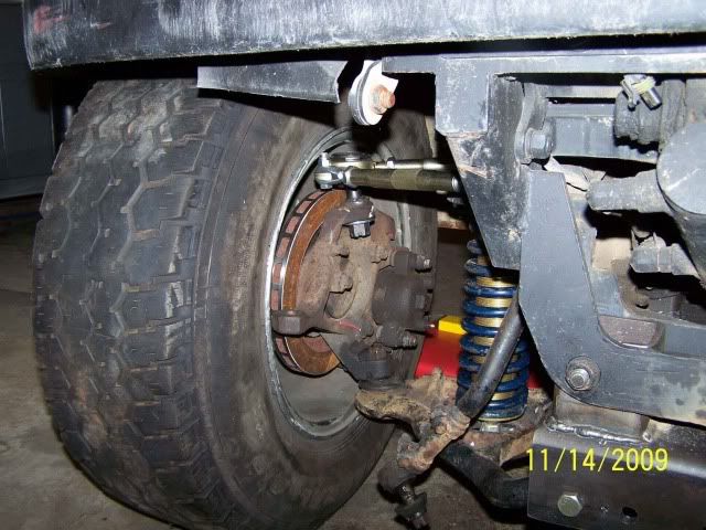
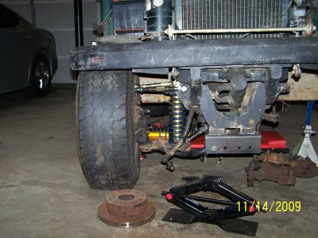
The upper control arm contacts the wheel (Jeep Wrangler 15x8 alloy)....not good, I put a 1.5" spacer that I had in the rear on it, and while I can mount it, It still makes some contact. See the pics. I can put a 2.5" spacer on it and that should allow it to clear the inside of the rim. Thoughts? Disadvantages? Max Speed is 40-50mph
The tires on the wheels are 30x9.50r15LT, As you can see in the pic, the tire is just way too big for the front (I like the big tire in the rear for speed but can change and will need to change the rearend anyway).
I'd have a few options. I can use different wheels, larger diameter and/or different backspacing to fix the control arm issue, As it stands the current rim width is 8" and i'm running out of smaller diameter tires that can fit a rim this wide.
Below are pictures of the issue. Let me know what options you think there are/what some suggestions you may have.
This is a Jacobsen Utility vehicle.....think Rhino on crack. Pictures are taken with the weight of the vehicle on the suspension (coilover almost fully compressed).
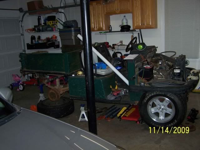
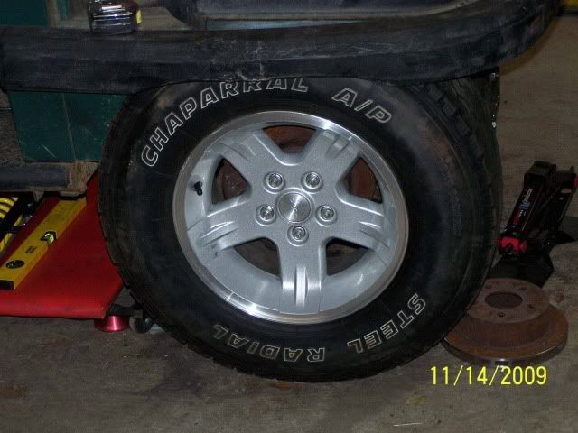
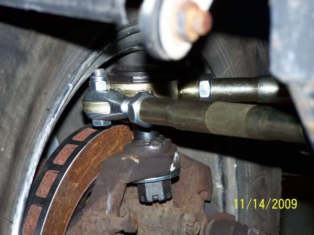
Are those spindles on upside-down?
In reply to SkinnyG:
Yep, they are Jeep Cherokee Spindles (2wd) that I had the current upper mount drilled out/tapped to accept a D44 style tapered insert wich i spot welded in place (screwed in) so that I could accept a ball joint comming out of the top.
Looks like a fun project!
One thing to check with EXTRA attention to the details:
Most Wheel stud manufacturers will say DO NOT USE SPACERS with our wheel studs.
1.5 or 2.5 inch spacers are large and will put large shear loads on the studs. If you go ahead and use the spacers make sure to replace the studs on a planned time frame (Annually?)
You probably want to look at increasing the wheel size....
Good luck.
Rog
Is there a vendor who makes better quality wheel studs for spaced out wheels? I understand that with the spacer i basically added a lever to the force applied to the studs.
Sounds like a larger rim is in order. 16" plus the spacer might allow me to clear the control arm, plus a 16x7 rim will allow me to run a smaller tire than the 15x8 rim.

zoomx2
Reader
11/15/09 5:18 p.m.
eebasist wrote:
Is there a vendor who makes better quality wheel studs for spaced out wheels? I understand that with the spacer i basically added a lever to the force applied to the studs.
Sounds like a larger rim is in order. 16" plus the spacer might allow me to clear the control arm, plus a 16x7 rim will allow me to run a smaller tire than the 15x8 rim.
http://www.arp-bolts.com/
Update, I have both control arms and coilovers installed with new rims and spacers.
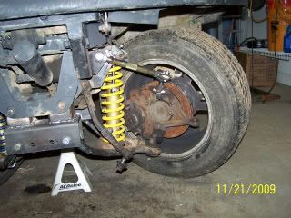
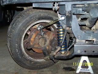
Right now I have 200lb springs on it, and it won't support the frontend, it fully compresses to the limit of the upper ball joint's travel. I was thinking that this would be no big deal since its a coilover and I can just move the adjustment screw till I'm happy.....well the screw doesn't much want to compress the spring when its loaded. Any thoughts?
I tried using a harbor freight spring compressor, but with the coilover in place I don't have enough room..
Thoughts/comments. The pics below show the suspension installed minus the steering.....it currently is supported by a jack in the middle. Part of me thinks I need a bigger spring rate, or a better way to compress the current spring and move the coilover collar.
I'm sure steering will proove to be a fun challenge.

I'd anticipate the steering being pretty, um, ferociously unpleasant with upside-down spindles. Is there a reason for doing this?

Keith
SuperDork
11/22/09 7:36 p.m.
My brother in law is heavily into rock crawling. He's not the most mechanical guy, but he does talk to people with brains. And one of the interesting things he's mentioned is that rock crawlers are far more concerned with droop travel than with bump travel. He's building a buggy right now that's going to have just an inch or two of bump and probably a couple of feet of droop.
On a street/track car, I usually aim for the car sitting with the shocks about 1/3 compressed at rest - ie, there's twice as much bump travel as there is droop travel. As pointed out, make sure you don't unload your springs 100% or you're not taking full advantage of the shocks.
I don't see a problem with inverted spindles as long as the rest of the suspension geometry is good. This doesn't exactly look like a high speed project anyhow 

44Dwarf
HalfDork
11/23/09 6:45 a.m.
Well....My geuss is the spindels are fliped due to him needing front steer units but what this did do is mess with the KPI angle. The angle formed by a line that runs through the king pin in the steering knuckle on a truck with an I-Beam axle. It's the same as the steering axis inclination (SAI).
I've not pluged any number in to the computer as to how this will mess with stuff but my guess is it will play funny with bump steer and camber curves and maybe caster gains..


