
So all this Challenge talk has reminded me that I have a long term idea for my GTV- not for a challenge car, but to be come a nice EFI with a catalyst so that it's more enjoyable to drive.
From a previous challenge project, I have an old Electromotive TEC II, which I can pretty easily change into a WinTECII. And with that, it offers some pretty basic a/f control, using a mapped Volts to air-fuel. But being when this was made, that set up only works for a narrow O2 (which I will call a EGO). EGO's operate between 0-1V, where 0 is lean and 1 is rich. Remember that part.
Also as part of the Challenge project, I have a DIY WB a/f meter from Australia- which I will call a UEGO. The output from this UEGO set up is roughly 0-5V, where low voltage is rich and high voltage is lean.
Now, it's not really hard to take a 0-5V to 0-1V, but the problem is that the signal is upside down.
For the electronics guys out there, where can I find a diagram to make a small board to take the 0-5V signal and invert that into a 1-0V signal? So that I can re-use my TEC II hardware?
Unless someone wants to swap a MS system for this TECII system.
The hardcore hardware hackers would call this an amateurish and overkill approach, but it's pretty cheap and easy: An Arduino of some kind would do this easily.
For a quick and dirty version, you could make it binary (on/off) by using a solid state relay.
Wire the coil leg to the output from your wideband and supply a constant 1vdc to the switch leg. Switch leg should be wired to where the switch leg is in the normally closed position.
when 5v (rich) is supplied to the relay coil the switch leg opens showing the computer 0v
When 0v applied to the relay coil the switch leg closes showing the computer 1v
wham bam, thank you ma'am.
A variable inverted signal is going to make me think a bit. Sorry
Turns out only the more expensive Arduino modules have a true analog output (and you don't need anything fancy), so you'll have to add a capacitor and resistor to smooth the high-frequency PWM output like this:
https://arduino-info.wikispaces.com/Analog-Output
Then you'd just need a little code to read the input value, do some math, and write the output value.
In reply to Hungary Bill:
If I wanted a binary a/f controller, I would use a simple EGO. No circuits required.
Even then, it's not binary- but would run as a limit cycle controller- that's pretty easy.
GameboyRMH wrote:
Turns out only the more expensive Arduino modules have a true analog output (and you don't need anything fancy), so you'll have to add a capacitor and resistor to smooth the high-frequency PWM output like this:
https://arduino-info.wikispaces.com/Analog-Output
Then you'd just need a little code to read the input value, do some math, and write the output value.
I didn't read the whole article- just got as far as the heading- taking a PWM to an analog signal- which isn't what I'm doing.
I'm want to take an analog 0-5V signal and change that to an analog 1-0V signal.
I get that, and if you're doing it with an Arduino you'd need an expensive model to do it without any other parts. Those instructions are for doing analog to PWM to analog using a cheaper model and a custom smoothing circuit. Either way can work but using your own smoothing circuit would be cheaper.
The UEGO doesn't have a simulated narrow band signal? I know my JAW controller has a simulated 0-1V signal along with the 0-5V signal. Been meaning to use it to replace the stock narrow band signal. My wide band only monitors a/f at this time.
The Hoff wrote:
The UEGO doesn't have a simulated narrow band signal? I know my JAW controller has a simulated 0-1V signal along with the 0-5V signal. Been meaning to use it to replace the stock narrow band signal. My wide band only monitors a/f at this time.
Good question, but it's not what I want. The simulated EGO signal is just that- for that narrow range that it goes from .2 to .8 in a/f, it switches just like that (between .98 lambda- 1.02 lambda- .8 to .2V- roughly, with 1.0 being .46V). So it's not a good conversion. But my UEGO does not have that output anyway- just the smooth 0-5V signal.
GameboyRMH wrote:
I get that, and if you're doing it with an Arduino you'd need an expensive model to do it without any other parts. Those instructions are for doing analog to PWM to analog using a cheaper model and a custom smoothing circuit. Either way can work but using your own smoothing circuit would be cheaper.
I had thought I've seen a simple circuit diagram that used an inverting amplifier. I'd rather try that than a full blow controller.

RossD
UltimaDork
10/26/15 12:05 p.m.
A transistor should be able to do what you need. The exact schematic is a bit beyond me, however. PNP or NPN
I think what you really are looking for is called a 'level shifter'. (EDIT: maybe thats just for digital signals... not sure.)
EDIT again. You'd want an inverting transistor amplifier with a gain of .2 to attenuate the signal.
So to clarify the ranges- I can focus the 0-5V to 1-3V. So I need 1-3v to 1-0V.
I can't view the circuit, but it sounds like this guy is trying to do something similar:
http://forum.allaboutcircuits.com/threads/convert-12-0v-to-0-12v-opamp.13694/

fujioko
HalfDork
10/26/15 2:38 p.m.
Simple inverting and level changes can be done with a transistor using 'common emitter' mode. Search youtube for common emitter circuit explanation.
In reply to fujioko:
That looks to explain the circuit, but I need to make one not knowing much about EE.
fujioko
HalfDork
10/26/15 4:47 p.m.
In reply to alfadriver:
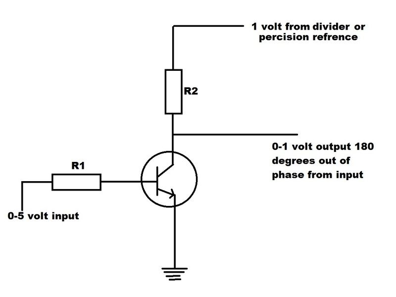 A lot of design elements to consider such as temperature compensation and input/output impedance. The above is just a simple circuit based on an NPN transistor such as a 3904. This would probably work but may be to sloppy.

pres589
UberDork
10/26/15 5:27 p.m.
In reply to fujioko:
Why "sloppy" assuming the proper transistor, resistor values, and a good 1VDC supply is found? Or is all of that the devil making the details potentially sloppy?
fujioko
HalfDork
10/26/15 6:31 p.m.
In reply to pres589:
The above circuit is more or less a starting point... it's literately a text book example. It will function like OP wants but may need some enhancements or tuning to live in the real world. Tuning a circuit for signal clarity and accuracy is tricky for automotive applications.
fujioko wrote:
In reply to pres589:
The above circuit is more or less a starting point... it's literately a text book example. It will function like OP wants but may need some enhancements or tuning to live in the real world. Tuning a circuit for signal clarity and accuracy is tricky for automotive applications.
And that skill is way outside what I know.
pres589
UberDork
10/26/15 7:22 p.m.
In reply to alfadriver:
Yeah, but I bet you know some people that could help.
While you could do this as a pretty simple analog circuit, as mentioned by GameboyRMH, it would be easier for you to just use an arduino or similar assuming a few milliseconds of delay is ok. Analog input pin, digital out with PWM (might need to filter this with a capacitor or something), few lines of code, easy. I could probably do it in a day or two and I'm bad at this stuff.
Kenny_McCormic wrote:
While you could do this as a pretty simple analog circuit, as mentioned by GameboyRMH, it would be easier for you to just use an arduino or similar assuming a few milliseconds of delay is ok. Analog input pin, digital out with PWM (might need to filter this with a capacitor or something), few lines of code, easy. I could probably do it in a day or two and I'm bad at this stuff.
I see what you are suggesting, but instead of a PWM, a analog output would be better- as I'm not sure if one can simulate a EGO sensor with a PWM signal. The PWM would be a frequency with a 0-1V span, and I don't think the input for an EGO would like that much.
Making that Analog out would be interesting.
fujioko
HalfDork
10/26/15 8:27 p.m.
Actually Kenny's got a good point.
I know somebody who is about to release some specialty Arduino signal conditioners and I have a few samples.
I'll have to check the specs on the samples but I might be able to gin up a precision converter.
From what I understand, the circuit is a wideband to narrowband converter with backwards input.
fujioko wrote:
Actually Kenny's got a good point.
I know somebody who is about to release some specialty Arduino signal conditioners and I have a few samples.
I'll have to check the specs on the samples but I might be able to gin up a precision converter.
From what I understand, the circuit is a wideband to narrowband converter with backwards input.
Which makes sense- but tuned to reflect what a ego would actually look like. The TEC II I have can program in an a/f response, so I can use the a/f mapped to the 1-3v range as specified to the 1-0v span, and make it work.
At least I can try.
I forget how exactly narrowband works, does it actually need to range from 0-1, or just bounce back and forth? If you just need back and forth a simple level shifter circuit and straight digital would be fine. If you need a true analog, knowing the sampling rate would be helpful.


