Ive been pulling my hair out about this one, Figured Id give the GRM crowd a chance to sort it out instead of a proper electronics message board (you guys like bacon way more).
Ive got this project which requires a midi input to a microcontroller (in this case an arduino cause I am impatient and too stupid for a real micro) that part isn't too important.
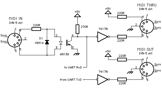
What is important is that I am having trouble getting the midi in to work properly, here is the circuit, I am just using the input part in my test rig:

The opto in question is here: http://www.sparkfun.com/commerce/product_info.php?products_id=314
The only resistors I could find in the bin were 280 ohm, which should work. My problem is this: Midi signals get through to the darlington, but it isnt pulling the signal all the way down, only a volt or so. I am measuring between ground and "to UART RxD", the signal is clean and the lines on the scope are nice and flat, MIDI spec is well within the frequency limits of the opto... What the crap!? I feel like such an idiot, this is an easy circuit.

JThw8
SuperDork
12/10/09 9:32 a.m.
You feel like an idiot?!? I understood "been pulling my hair out" after that you lost me.
Needs more bacon....and fire, everything is better with fire.
This will have nothing to do with fire at all 0=)
certainly wont be switching solenoids, not of any type, and in no way will they be connected to propane.

JThw8
SuperDork
12/10/09 10:07 a.m.
Tetzuoe wrote:
This will have nothing to do with fire at all 0=)
certainly wont be switching solenoids, not of any type, and in no way will they be connected to propane.
Electrically controlled/propane fired bacon cooker!

kcbhiw
Reader
12/10/09 10:15 a.m.
Try increasing the size of the 270 ohm resistor. Throw in a 470 and see what happens.
ooo, larger resistor, Ill try that, I tried taking another 280 from the bin and pressing the leads against it in parallel (cut it in half).. needless to say it didn't do much. Ill try that when I get home.
My guesses would be that (1) you're not driving the input of the opto hard enough or (2) you have a defective opto or (3) the opto is too slow for the data stream. In case 1 you might try removing the diode and/or the 220 ohm. Try applying 5V directly to pin 2. If it switches then the opto and the rest of the following circuit is good. Then apply a 5V square wave generator to pin two. Adjust the frequency up and see if the opto flakes out. If it works OK then you probably need a driver stage in front of the opto. If all else failed add bacon.
If what you are saying is reaching my eyes correctly... Put a 1k pot in place of the 270R and keep turning it up until the magic happens. Replace with correct value of resistors.
Have you tried disconnecting the 7417 from it and then looking with the scope? And +1 on a larger resistor if everything else looks good.
1 Im not 100% sure about, Im using a cheap usb to midi dongle and was able to somewhat check out the midi signal in with reference to midi ground (not what is used in that circuit). I removed the diode and there was no change in the output from the opto. I also dont have a frequency generator.. Can I make one with bacon?
for 2 and 3, I was looking at the output of the scope and there are no signs of the signal ramping down in any way (was quite clean when I zoomed wayyyy the F in) , I do however have two optos... I was saving the other for when I was done poking around and giving it all kinds of weird "lets see what happens if" inputs. The data sheet specs it should handle 14 microsecond pulses, which is well within midi spec, the scope is at 100us increments and clearly displays the whole bitstream
Excellent suggestions though (I love this board  )
)
the circuit stops before the inverter, im not adding thru capability until I order PCBs
It might be that the cheap USB/midi dongle is a problem, in the same way that the cheapy USB -> Serial converters never work with a Megasquirt.
Do you have another MIDI source you can borrow?

TJ
Dork
12/10/09 11:02 a.m.
Is the problem frequency response or the gain being too low?
A higher value for the collector resistor will increase the gain - I would try that first.
A quick look at the Siemens 6N138 datasheet suggests that it should handle that sort of frequency response - IIRC MIDI is something like 30kBaud, the 6N138 is supposed to handle up to 100kBd.
yeah its 31250, roughly 320us to send a byte, I have no other midi thats why I bought the 5 dollar dongle 
Hmm. No chance trying out that dongle somewhere else, I assume? Musician friends?
I'm just wondering if you're trying to debug two devices at the same time. That's usually not a good starting point.
right, I think I gave away all my old synths (bad move) and the only other stuff I have is way up in PA.. anyone know any northern VA places like 69th street music in PA, its a used music place where you can (sometimes) barter down the prices on stuff.
1k Resistor did it!! weeehew, now on to the keypad and software part... Man im glad that worked off the bad, wasnt ready to handle intense trouble shooting in my post happy hour state.
ah see that already exists with RF filters in block diagrams:

...which I am now henceforth referring to as bacon filters
True, but the bacon and egg plate is more filling. 
hahahahaha I see it now, I thought you were just putting bacon on whatever. clever clever.
As a member in good standing of the gEEk club (inactive), I nominate Mojo to the position of honorary gEEk.
Remember, you can't spell geek without an EE. 


