Presented by Nine Lives Racing
cpatersontn
cpatersontn New Reader
12/16/23 11:01 a.m.

Background:

We currently run our 1991 BMW 325i (aka Sabine) in NASA SE30 and ST6 where there are no aero mods allowed. We have an opportunity to run a few races in 2024 in NASA ST5 and other series (e.g. Champcar, Lucky Dog) with aero so we're going to be making some mods to the splitter and rear 9LR rear wing. 


For the rear wing, we're allowed to run a Gurney flap and larger end plates (max area of 144 sq in). The 9LR wing has a slot for a slide-in Gurney and the stock end plates are smaller than the allowed larger spec. 


So... assuming we want to bump up the rear df and minimize any drag penalty, are there any good rules of thumb on how big to go with the Gurney and what the new end plates should look like and also placement? Everything I'm reading says bigger is better to a certain point so we'll max out the area.


This article had some good info but not sure how universal it is for our application. https://baero.tech/blog/2018/4/26/finished-endplate-data

1. Should the leading edge of the end plate be in front of the leading edge of the wing? If so, how far in front? 

2. How far above the wing should the top of the end plate be? 

3. How far should the trailing edge of the end plate be to the trailing edge of the wing? 

4. How big should we go with the Gurney flap? Looks like 9LR goes up to 3/4". What's the thinking on these? Bigger is better up to a point? 

From the article, they started with this simple rectangular end plate: 


and ended up with this one:


sleepyhead the buffalo
sleepyhead the buffalo PowerDork
12/16/23 12:15 p.m.

if drag is important, the the answer to one of your questions is pretty straight forward based on the data 9LR has published:

the L/D always goes down when adding a Gurney flap on the Elan foil that 9LR sells.

what's the existing dimensions of the rear foil you have mounted?  What's the maximum width you can get the span out to w.r.t. the rules?  What are the limits of how far back the foil can be (overhang)... and where is the back edge of the foil now?

cpatersontn
cpatersontn New Reader
12/16/23 2:43 p.m.

Testing will show how much drag vs DF we can take before it starts to negatively affect lap times. Just using a 3" simple flat splitter (no air dam) and the 9LR wing netted 2 seconds a lap lower than we ever ran at NCM this Fall. Felt WAY more planted through sweepers and braking zones. Confidence building.  

Wing is 65" wide x 9" chord. That is about as wide as we can go per ST5 rules. It's also back about as far as we can go without rear bumper type mount which we don't want to do.

Stock 9LR end plates are 10"W x 8"T. The leading edge of the end plate is 1" in front of the wing leading edge. Top edge of the end plate is ~ at the top fo the airfoil. 

We'll likely bring a couple of Gurney flaps to play with from 1/4" up to 3/4" depending on the track. 


sleepyhead the buffalo
sleepyhead the buffalo PowerDork
12/16/23 9:55 p.m.

based on those rules... and assuming the 9LR wing can handle ~375#s of downforce when endplate mounted at 65"...  I'd be advocating strongly that y'all make a plug for the end of the wing that serves as a mount and pivot and that you look to fab or move the uprights out off the trunk lid and either into the "rain rail" or the rear body work outside of the trunk.

assuming your rear uprights are ~40inches apart... similar to a miata... there's a significant amount of flow disruption due to the uprights and the endplates and their proximity to each other.  "end plate mounting" the rear foil will significantly be reduced this flow disruption; and it will have the added benefit that the "upright"/mount now becomes the endplate and isn't constrained to 144in.

otherwise, your next best option is to build a 4 to 6inch tall extension of the upright to move the rear foil up so that the top of the foil is the same height as the roof of the car (based on the photo above, it looks like the foil is below the roof by ~4in.  if you're doing that, having this "upright lift" also push the foil back any amount would be advisable.

benefits due to the endplates, in my experience/opinion, will pale in comparison to what can be found by move the wing further out of the cabin's wake, and/or getting it further back behind the trunk and extending the moment arm from the foil's "quarter chord" to the CG (since the moment arm from the front of the splitter to the CG isn't going to change).

cpatersontn
cpatersontn New Reader
12/16/23 11:27 p.m.

Great points. We've been toying with the idea of raising the wing up as you noted. We're pulling all the strings possible so will take a look at this too. 

spedracer
spedracer New Reader
12/17/23 12:59 p.m.

Somewhere on Occam's Racers, and for sure in the report you can buy, there's discussion on end plates. His results suggest there's not gains big enough to bother chasing, at least at the club level. https://occamsracers.com/

sleepyhead the buffalo
sleepyhead the buffalo PowerDork
12/17/23 7:33 p.m.

I was hoping to avoid this; but I guess not:  There's some issues with both the baero and occam's end plates articles, that might not be obvious to the lay-reader.

Firstly, I'm a little suspect of baero's data, based on this initial image:

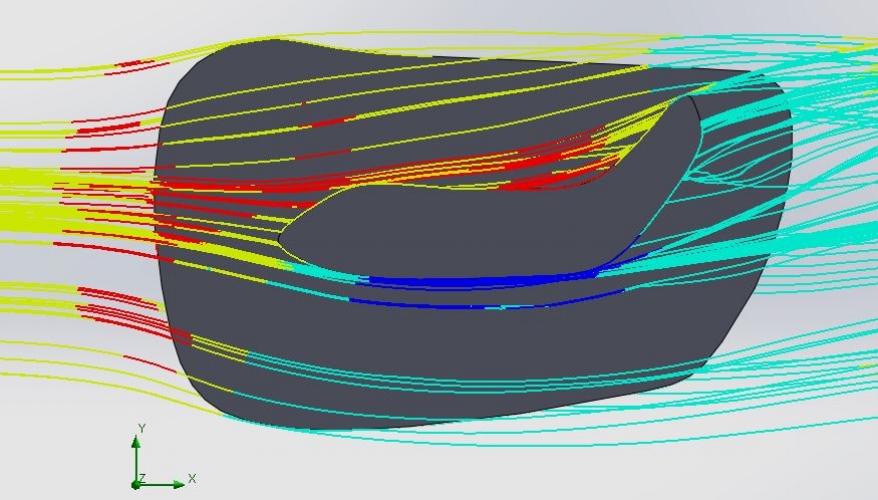
I have an APR GT500 foil profile I still need to digitize... but it definitely doesn't look like that.  I suspect that overly small nose radius (and other issues with the leading edge foil shape) on that digital foil is creating some influence on the end-goal endplate design.

However, there's a more important misunderstanding that I feel is shared in both articles, and it's a fundamental misunderstanding of what the tip-vortex is, and how it's created/developed.  The reason I bring that up, is because the tip-vortex is what any endplate/winglet is attempting to influence.

baere said:

We want the max pressure to be right on top of the airfoil and the min pressure right below it. This will create the maximum amount of downforce.

Mario-Occam said:

Given that information, and after looking at the preceding image, you might conclude that a good endplate should be shaped to exactly cover the high and low pressure regions of the wing. And from that, you might surmise that a good endplate for a 10” chord motorsports wing should extend 10” below the wing, and should have a lot of surface area concentrated at the front. And that’s how I see it as well. However, some end plates have most of the area towards the rear of the wing, and I can’t say I understand that.

Both of these authors see to think that the end plate needs to be biased forwards to cover the low pressure flow generated by the suction-side flow acceleration zone in the front ~30% of a foil.  By implying that the endplate needs to cover this area, there's an implication in both articles that the high-pressure side of the flow can wrap directly around the tip without "going backwards", despite the wing traveling through the air forwards.

Mario's explanation is particularly problematic because he's using the chord to define the size of the endplate ("10inch chord wing should have a 10inch tall end plate").  It's unclear based on the article (and the report) if he's come to that conclusion because the low-pressure zone graphed is the same size as the chord of the pictured 2D foil... or if he's come to this conclusion because of some other influence.

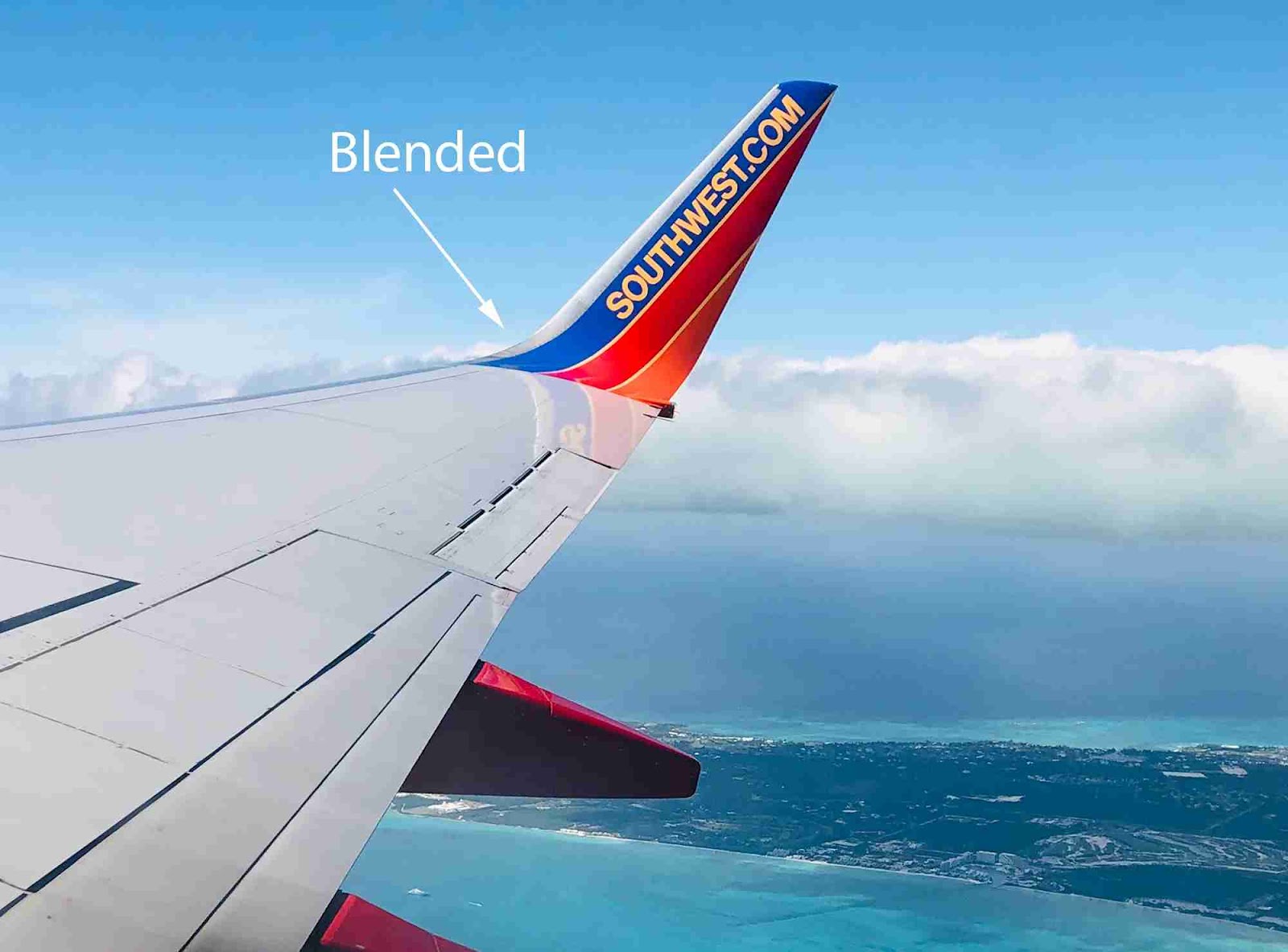
The current Aerodynamicist/Aerospace Engineering understanding is that tip vortex is wrapping from the high-pressure to the low-pressure side while traversing longitudinally (i.e. backwards); and that's why the majority of winglets on an aircraft wings are bias the area towards the back portion of the low-pressure side of the wing:


(https://airlineworld.files.wordpress.com/2008/10/south_african_winglet_close-up.jpg)

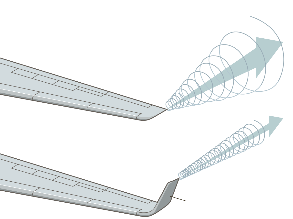
The broader picture though, is that the entirety of the high pressure across the span of the wing is attempting to wrap around to the entirety of the low pressure on the other side of the wing.  The tip is resolving the entirety of of the pressure differential of the 3-dimensional finite-span wing.  That's why one of the more commonly known regimes of flight is "Ground Effect", which is usually calculated as some percentage of the wingspan above the ground (although, there's a further band of ground effect that's calculated as a percentage of the chord above the ground {perhaps this is where Mario's confusion is coming from?}).

You don't have to take my word for it, you can calculate the efficiency benefit of an endplate via these formulas that are part of Katz's "New Directions in Race Car Aerodynamics" as cited by Mike Fuller on Mulsannes Corner.  Which is in-line with what you can find in other places about end plates, which is that they generally have a similar benefit as extending the wing in span the same length as the winglet (this is an oversimplification).

Keith Tanner
Keith Tanner MegaDork
12/17/23 9:15 p.m.

Now I'm thinking a 3D printed winglet would be a really interesting project. How would it be shaped for a 2D wing that doesn't have the taper in plan that an airplane wing does?

sleepyhead the buffalo
sleepyhead the buffalo PowerDork
12/17/23 10:03 p.m.
Keith Tanner said:

Now I'm thinking a 3D printed winglet would be a really interesting project. How would it be shaped for a 2D wing that doesn't have the taper in plan that an airplane wing does?

The first question of any motorsports project is:  what's the rule set?  cheeky

one of the challenges cpatersontn faces is the dilemma of not wanting to waste span in the service of endplate thickness.

further, are you thinking you'd want an end plate that's "blended" like the 737's?

or are you thinking about more exotic options?  I assume this is most likely to end up on an NA/NB (although NC and ND should be similar)?  Any particular "base" wing that you'd be putting these on?

WonkoTheSane
WonkoTheSane UltraDork
12/17/23 10:45 p.m.
Keith Tanner said:

Now I'm thinking a 3D printed winglet would be a really interesting project. How would it be shaped for a 2D wing that doesn't have the taper in plan that an airplane wing does?

This is EXACTLY what I was thinking while reading through Sleepyhead's post...

spedracer
spedracer New Reader
12/18/23 12:43 a.m.

In reply to sleepyhead the buffalo :

Thanks for the post/correction/additional insight. I'm certainly a lay person reader. Makes more sense then the conclusion of "everyone selling fancy endplates is ripping you off", which was my semi-confused takeaway from the Occam's article. I'll have to look back over the report, I recall there weren't big gains in any of the endplate designs tested, but can't remember which were actually tested.

Keith Tanner
Keith Tanner MegaDork
12/18/23 1:21 a.m.

In reply to sleepyhead the buffalo :

No rule set :) 3D printing would allow for the blending as well as the angle. I'd be putting it on an old nascar COT wing mounted on an NA, but if it works it would be a fun addition to Big Wang products.

sleepyhead the buffalo
sleepyhead the buffalo PowerDork
12/18/23 8:36 a.m.
spedracer said:

In reply to sleepyhead the buffalo :

[...] I recall there weren't big gains in any of the endplate designs tested, but can't remember which were actually tested.

I think there were some gains from one end plate, which had a gurney flap on the outside.

which brings up two important complications that should be covered.  1) that motorsports endplates will see a significantly larger range and change of side-slip (beta) angle than any aircraft winglet.  2) the shape of the vehicle ahead of the rear foil & end plate has a significant impact on the flow the winglet is going to be reacting to.

it's easy to think about the flow coming over the roof of the E30, and then turning to follow the glass (with layers above that turning less) and then the trunk.  if "we" were/able to look at the flow from above, then there would likely be some of the flow coming along the side being turned past the c-pillar and onto the rear glass/trunk as well.  I suspect this is happening less on the E30, though, than a miata with a hardtop... because the E30 has sharper c-pillar than the rounded shape of the miata hardtop.

cpatersontn
cpatersontn New Reader
12/19/23 5:58 p.m.

Ok, with all of that said, we currently have stock 8"T x 10"W end plates that can go as big as 12" x 12" (or equal 144 sq. in). The current end plate is 1" ahead of the leadedge of the wing and flush with the top. Not sure add more length in front of the wing leading edge helps but could see add more height below the wing and some behind. That could be adding 4" more below and 2" more behind. Good idea or just not worth the effort?  

You'll need to log in to post.

Our Preferred Partners
Yht7n4i8mnWbOaEmb14WaFwUuRh4x1JcHf1QrJrRVUOArStbe6zoBbD81JfnyIAF