1 2
JoeTR6
JoeTR6 HalfDork
8/18/13 7:20 p.m.

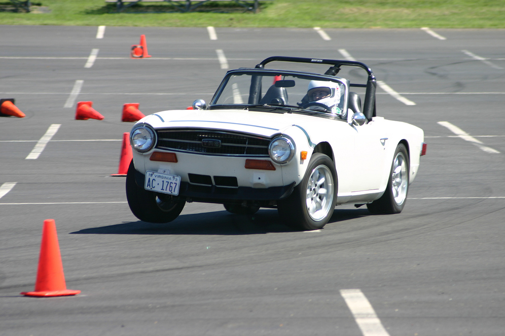
Even though it's pretty far along, I thought I should start a build thread for this project. Maybe someone will learn something (including me). This car has been in development since 1999 or so. First, this is actually a friend's car that we've been working on together. It started originally as a $600 car with brand new Michelin Redline reproductions, themselves worth the purchase price. After welding in some new floorpans and rockers, the chassis was pretty much rust free. The frame is as clean and straight as any I've seen. That said, it flexes like crazy at an autocross.

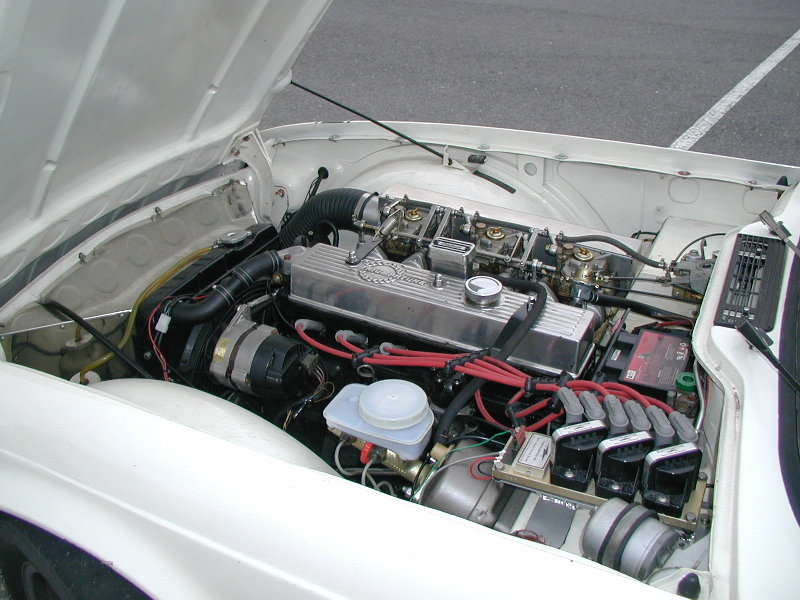
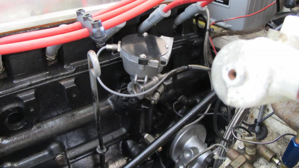
The car was originally set up for autocross with a rebuilt motor and triple Weber DCOE 40 carbs (gotta love intake howl). Once the jetting was sorted, it ran fairly well and revved better than any TR6 I've ever driven, mostly due to an aluminum flywheel and head work. The suspension has many Richard Good upgrades including springs, sways, Spax adjustable front shocks and adjusted rear lever shocks (thanks to JK Jackson). Front hubs and stub axles are upgraded, and the rear hubs are adapted from a Corvair. Front brake calipers are from a 1980-something Toyota 4-Runner, necessitating a larger Jaguar brake master cylinder. Rear brakes use Datsun 240Z alfin drums with Austin Healey larger bore wheel cylinders. We added an Electromotive HPV-1 ignition early on with good results. The wasted-spark setup helped burn some (but not all) of the extra fuel the Webers dumped into the engine. Plus, ignition timing was spot on compared to the original Lucas distributor.

The car ran like this from 2001 until sometime in 2009 when the oil pressure began dropping. Power was still good, but running an engine at 6000 RPM with only 35 PSI of oil pressure is not a recipe for success. The motor was pulled and disassembled showing that the cam was wiped with major pitting/erosion. Some of the debris must have ended up in the oil pump making it work less than good. Surprisingly the rest of the motor, including the bearings, were in good shape. We're still not certain what led to this. Perhaps using oil without ZDDP for some amount of time. Possibly gas getting into the oil, reducing it's ability to deal with a high-lift cam. In any event, the motor was rebuilt. A crank scraper and oil pan baffle were added to help keep oil pressure steady (another possible cause of the cam failure).

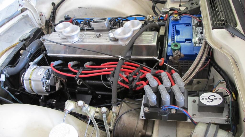
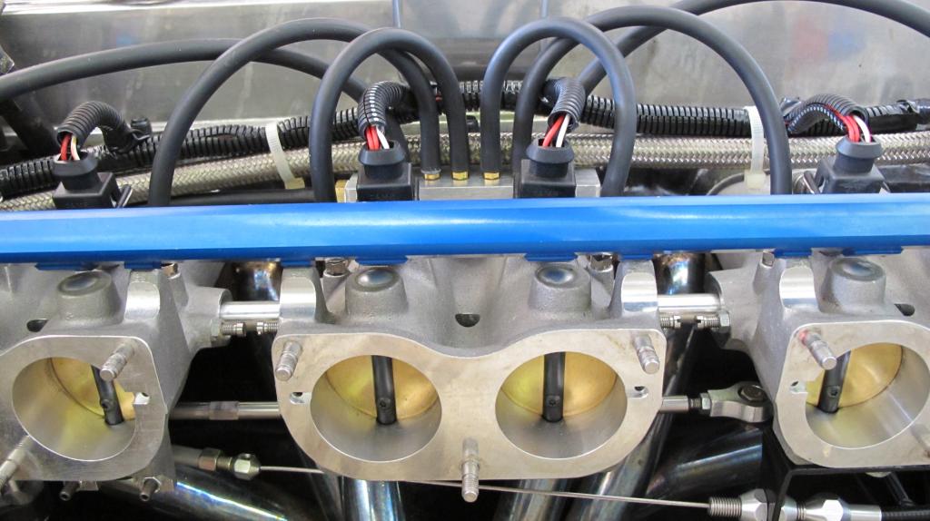
We are now using Brad Penn oil, but the Webers would still continue to wash down the cylinder walls with fuel. That's when we decided to try modern fuel injection. Engine rebuilds aren't cheap, but neither are fuel injection kits. I choose to use a Megasquirt ECU and a TWM/Borla intake. I considered attempting to make my own intake, but this was just too much time/effort on my limited time/knowledge budget. Once these were acquired, the engine was refitted with the Webers for break-in. A wide-band O2 sensor was added (replacing a narrow-band used for "tuning" earlier). This helped dial in the Webers much better than before. Almost enough to make me want to stick with them. Bah, what's the fun in that.

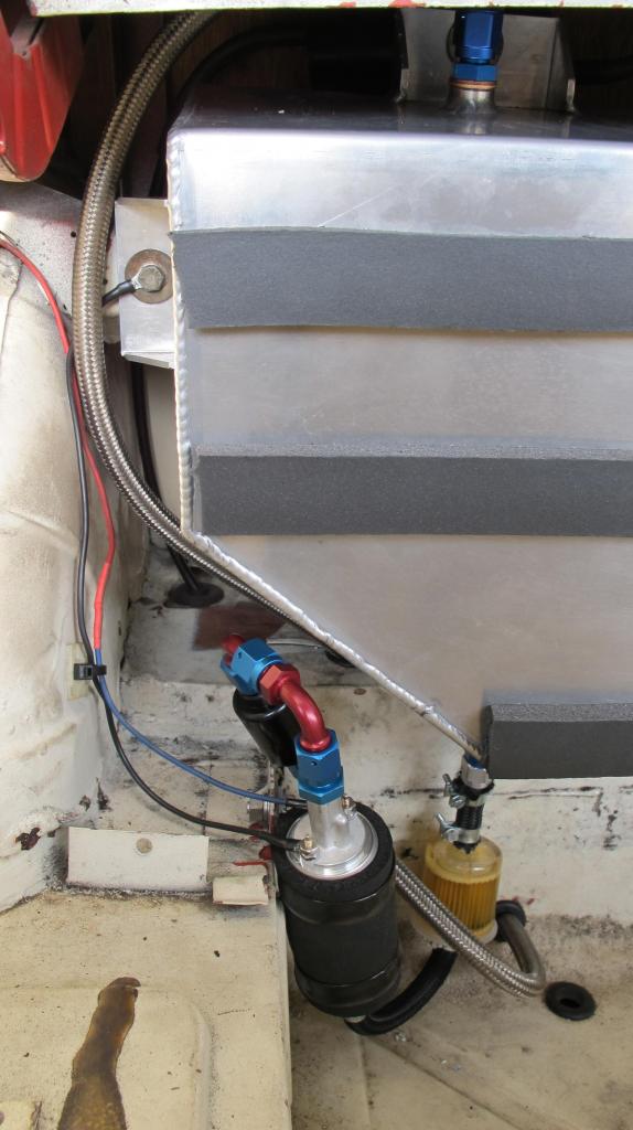
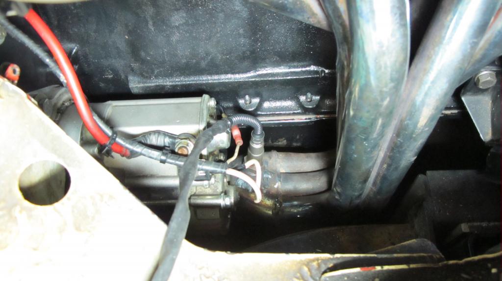
Once the engine had 600+ miles on it, we installed the Megasquirt running just the ignition. This allowed checking all of the sensors without quite so many variables to get right. So far so good, the intake was bolted up. It turns out our tubular header has much larger radius bends than the stock header, so the TPS wiring plug and throttle linkage ran into the header. Nothing some JB Weld on the throttle shaft wouldn't fix (to relocate the flat spot). Actually, this caused a reroute of the throttle cable towards the front of the motor in order to eliminate a bell crank in the linkage. This was fixed with a custom bracket and longer cable. While installing the new intake, the O2 sensor was moved as close as possible to the engine directly on top of the 6-to-1 collector. This made the O2 sensor a bit more responsive and keeps it away from moisture in the exhaust. New 3/8" fuel lines were added to keep the fuel flowing and provide a return line. The aluminum fuel tank has baffles and a built-in anti-surge reservoir.

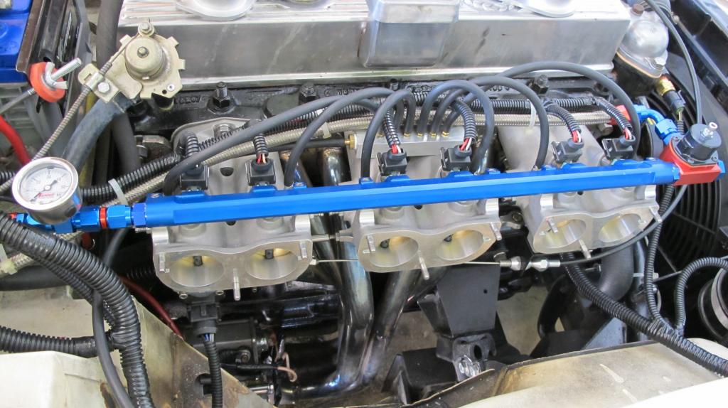
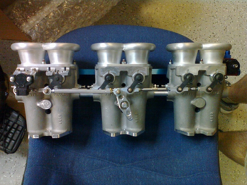
First start-up running fuel injection was last weekend. Now it's simply (hah) a matter of tuning and fixing all of the issues from the install, such as grounding the crank VR sensor shield wire to the Megasquirt. The original MAP sensor port was drilled into the end of the manifold balance tube. This provided a very noisy signal, so I made a vacuum manifold from some aluminum bar stock. This ties the six individual vacuum ports to a single outlet via a small (7/16" round x 3") cavity. Adding a restrictor between the vacuum manifold and the MAP sensor doesn't appear to be necessary based upon TunerStudio logs. The intake has 45mm throttles, so that coupled with an aggressive cam gives an idle vacuum of 55 KPa. But it responds well to throttle and is fairly smooth. One thing I've only played with a bit is acceleration enrichment. I've added enough fuel and duration to keep the engine running when the throttle is opened, but it still goes fairly lean. I'm currently using alpha-N for engine load, but will eventually go back to trying the ITB load scheme that MS 3 supports.

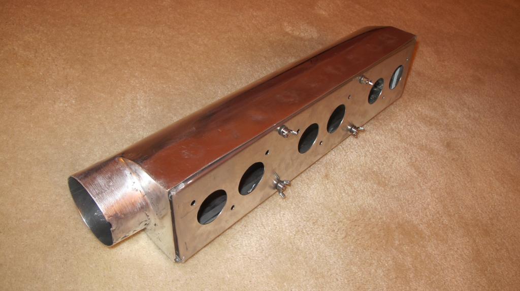
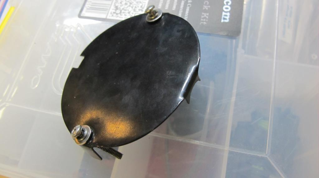
And that's where this project is at the moment. Pretty soon we'll need an air box to keep from FODing the engine while trying out TunerSudio's autotune feature. I'm working on that this week along with getting some pictures of progress so far.

sethmeister4
sethmeister4 Dork
8/18/13 9:18 p.m.

Pics!

grafmiata
grafmiata SuperDork
8/18/13 9:49 p.m.
sethmeister4 wrote: Pics!

+42.

Sounds like a cool project!!!

JoeTR6
JoeTR6 HalfDork
9/9/13 8:51 p.m.

It's been a while, but I finally downloaded some pictures. First, the before shot taken in Nov. 2002 when the paint was fairly fresh.

AutoX-Nov02_sm_zps1f7f3f1b

Here's what it looks like now.

IMG_2431_zps69ed88a9

And from a more interesting angle...

IMG_2433_zps0a4b7e66

I've been fabricating an air box from aluminum. It just needs to be installed.

IMG_2440_zpsc27b4cc7

The car starts and idles fairly well. Once the air box is in and we fix some oil leaks (bad even by Triumph standards), the car will be ready for a first drive.

bgkast
bgkast HalfDork
9/10/13 4:52 p.m.

Hot!

mightymike
mightymike Reader
9/10/13 6:21 p.m.

Very nice. Watching with interest.

RossD
RossD PowerDork
9/10/13 8:10 p.m.

Very cool! Moar pictures!

JoeTR6
JoeTR6 HalfDork
9/10/13 9:26 p.m.

My favorite picture of the car in action. Notice any chassis flex?

1297810963_8195bb28a6_b_zpsfa2d73f8

Running fully sequential injection required a cam sensor. Using an old distributor with a single-tooth wheel worked pretty well.

IMG_2437_zps40b597a5

The fuel tank is from the UK. I wish I could weld aluminum that cleanly.

IMG_2430_zpse7403a3d

Details of the throttle body. Notice the vacuum manifold.

IMG_2434_zps3cb1b792

The throttle linkage is underneath, but the original setup didn't clear the tubular exhaust manifold. The only way I could see to route it was to pull from the front. TWM really should have reversed the butterfly rotation and made the linkage pull towards the rear.

JoeTR6
JoeTR6 Reader
9/14/13 7:39 p.m.

Ever done a mod that, while very worthwhile, came back to bite you in the ass in a major way?

I went to fix the oil leak coming from the lower part of the engine. It's mostly coming from the sealing block that spans the front main bearing, giving the timing cover and oil pan something to bolt to. In their infinite wisdom, Triumph made this part out of aluminum, so the threads tend to strip. This left the timing cover with almost no torque on the bottom bolts. The machinist didn't catch this when he bolted the timing chain cover on and I didn't think to check before putting the engine in the car. BTW, the front frame cross-member makes it impossible to helicoil in situ, at least without removing lots of stuff.

No problem. You can drop the oil pan on a TR6 without removing the engine. Oh, unless you added a windage tray that limits movement with respect to the oil pump. Crap. Of course, I didn't realize this until I had separated the oil pan and ruined the gasket, probably getting some dirt in there as well. To complicate things, we also have a crank scraper (with a spacer) that is necessary for the crank to clear the windage tray. That was responsible for at least some of the leaking oil too.

Man, I hope that lifting the engine an inch or two will allow the oil pan to clear. I really don't want to pull the engine again. Time for beer.

stitchit
stitchit
1/5/14 12:18 a.m.

Hi love your work, just doing some research for my own TR6 which I am converting to sequential EFI and wasted spark ignition. Have been scratching around looking at various was to use the old dizzy for the cam sensor, I would be interested to see how you have done yours if you are happy to share. I will be using a rebuilt set of 6 PI manifolds and MS3 the manifols have a balance pipe with provision for MAP X2 and MAF without mods, although I will need to have the exhaust moded for the wide band. I also have the 69 PI 150 head which will have some cleaning up as well. The Trigger wheel is fairly simple, but the cam sensor was another matter, I was wanting to try to use a Petronix style trigger with just one magnet but not sure if it will work.

I would appreciate some feedback. Regards Greg

JoeTR6
JoeTR6 HalfDork
1/8/14 7:13 p.m.

Hi Greg. I've been slowly putting the car back together after (hopefully) fixing the oil leaks. I'm changing the VR crankshaft sensor to a Hall effect gear-tooth sensor to fix an issue with electrical noise coming from the electric cooling fan motor.

For a cam sensor, I gutted a Lucas distributor and mounted a threaded Hall effect sensor in the hole where the lead terminal goes. The original hole took some widening and rounding off. I made a single tooth cam and bolted it to the top of the distributor shaft. The sensor is a little close to the #4 plug, but I haven't noticed any issues. The sensor came from DIYAutoTune. The nice thing about this type of sensor is they have their own internal magnet and work with any steel toothed wheel that is a minimum 2mm wide with 2mm tall teeth. They require 5-24 volt power, so I just branched off the TPS reference voltage wire. I'll take some detail pictures this weekend after we get the car running and possibly driving.

Jack
Jack SuperDork
1/9/14 9:40 a.m.

I'm still in process with MS-EFI for my 1980 TR8. My easy way to fill you in is here: http://74.124.198.224/~success/viewtopic.php?f=92&t=22528&sid=1ecb412955fff89cda711e29a3c38f1d

Obviously, I've been sidelined with other stuff as the dates are older, but the car runs and drives. I just need time to finish it up. It's a fun process.

Good luck!

JoeTR6
JoeTR6 HalfDork
1/13/14 7:50 p.m.

Here's a picture of the cam sensor internals. I had to cut down the shaft and thread the end for a nyloc nut, so this may not be the best way to go unless you have a pile of old, worn distributors.

IMG_2709_zps6c6d617e

I made a simple cover to keep stuff out. There's not much to go wrong inside anyway.

IMG_2710_zps495b82cb

Here's where the wide-band sensor ended up.

IMG_2713_zps8a4275cc

The car started up for the first time in months this weekend. I was just trying to build up some oil pressure, but it fired up on the first try. For some reason, the fuel pressure was a bit higher (47 psi instead of 43.5), so it ran a little rich. Once it warmed up, it settled into a smooth 1000 RPM idle. It moved under it's own power long enough to turn it around, so everything seems OK for a test drive once the tunnel cover is back in.

The next issue to tackle is the low idle when cold. We don't have an IAC or cold-start valve on the intake, so I'm going to play around with the cold vacuum advance. My thought is to retard the timing at idle when warm and open the throttle stop a bit until the idle is good. Then I can advance the timing and enrich the mixture when cold to raise the idle speed.

The new hall effect sensor fixed the crank sensor noise problems. The tach signal is now perfect at any RPM.

I still need to do the final balance on the ITBs.

JoeTR6
JoeTR6 HalfDork
1/20/14 7:52 a.m.

I think we've entered the tuning phase of this project. After bolting in the gearbox tunnel, center console and air box, there was nothing left to do before the first test drive. Driving around (gently at first) with auto-tune enabled showed no problems, so we took it out for some hills and faster acceleration runs to tune higher engine load areas of the fuel map. The only problem was a momentary lean condition (~17 AFR) when the throttle is opened slowly. That should be fixable with some tweaking of the acceleration enrichment settings.

Things may get more interesting when we reach the threshold where the engine load calculation switches from MAP sensor to TPS (we're using the ITB load calculation). For lower engine loads, the MAP sensor appears to work fine. Maybe we should wait for dyno tuning to test out the higher engine loads since 1) it's hard to use a computer in an open car during winter when it's pinned between the passenger door and the shift lever and 2) cops frown upon full throttle acceleration runs on the street.

JoeTR6
JoeTR6 Reader
2/20/14 4:55 p.m.

After the last tuning session, I got enough log data from TunerStudio to fine tune the ITB load settings. Up to this point, we've just been tickling the throttle because I wasn't so sure about the transition from MAP load to TPS load at various RPMs. Well, now it's good enough to crack the throttle open. I did some more tuning, carefully increasing load and adjusting the fuel map. The results are quite nice. Near WOT street runs feel as good as with the Webers but without the overly rich exhaust smell. The AFR is OK assuming steady throttle inputs are used. Once acceleration enrichment is tuned, this thing will rock.

I'm still leaning towards some dyno tuning to milk all the power out of it we can get. At least now I know it's safely drivable.

irish44j
irish44j PowerDork
2/20/14 4:58 p.m.

I always enjoyed watching you run this car back when I used to autocross with CDC. Gave me a bit of inspiration while I was working on the GT6 rebuild

JoeTR6
JoeTR6 Reader
4/5/14 8:41 p.m.

We had our first autocross running with the fuel injection on March 22. Besides idling between 2000-2500 RPM after a hot run, it went pretty well. The car goes like stink on a hot day. I backed off the throttle stop to bring the idle down when hot, and that mostly worked. The ignition retard at idle I was using to drop the idle down is configured to only engage below 2000 RPM and coolant temp. above 140F, so once the idle is high it stays high. So with no provision for idle air control, how do I keep it running when cold without using lots of foot? I'm already advancing the ignition timing 5 degrees when cold.

Since we're not using the idle trim screws, I'm thinking about blocking off their intake ports behind the air horns and hooking the outlet ports after the throttles to a fast idle valve via a manifold. I'm not certain how much effect this will have on idle speed, but can simply open them all the way to find out. I'd like to avoid drilling holes in the intake, but I guess it may come to that. A less good solution would be to block the throttle open a bit when cold, but this defeats a few "at idle" settings on the Megasquirt due to the throttle not being fully closed. It at least has the advantage of being less a pain in the ass than using a foot during warmup.

erohslc
erohslc HalfDork
4/5/14 9:20 p.m.

An alternate cam sensor solution (assuming that you are not using the mechanical fuel pump) is to braze or grind a steel 'tooth' about 1/8" wide onto the camshaft pump drive lobe. Drill a suitable hole in your fuel pump blanking plate for a Ford Escort 1.9L cam sensor, and position it to read the 'tooth' as it passes by (the cam sensor has an integral magnet). You will have to do a bit of fiddling to determine the correct phasing of the 'tooth', or perhaps the MS software can be configured to take care of that detail. You will also need to take some care with sealing. The sensor has an integral O-ring, so an aluminum tube of proper inner diameter to seal, attached to the blanking plate can work. Cut a split into the outer end of the tube, and then use a hose clamp to clamp the sensor firmly, after you have adjusted it to just clear the 'tooth'. Having deleted the dizzy, you must now provide a means of retaining the dizzy/oil pump drive gear with specified end float (don't want to lose your oil pump drive, right?). The lower part of the dizzy pedestal performs this retaining/end float function. Separate the dizzy mounting pedestal from the dizzy (or find a scrap one), and find a suitable freeze plug for the hole (1" ISTR but measure it, Dorman). Use the factory workshop method of measuring and setting drive gear end float with paper shim/gaskets fitted between pedestal and block, then install shims and pedestal (sans dizzy, but with freeze plug).

Voila! No useless dead albatross of a dizzy getting in your way, cam position is sensed for MS SEFI, oil is sealed inside the sump, and drive gear end float is maintained.

JoeTR6
JoeTR6 Reader
4/6/14 8:11 p.m.

I suppose you could read cam position directly from the cam. Ideally, the cam tooth should be 10-20 degrees before the missing tooth on the crank. In our case, we still use the mechanical tach even though there's an electronic one on top of the dash. Plus, it's a lot easier to set the sensor gap and things are already sealed up. Eventually I want to install an oil separator, and the best place to put the drain is in the blanking plate where the fuel pump used to be.

Today I played around with the bypass screws. With the throttles all the way closed, I opened the bypass screws all the way. This allowed the car to idle at around 900 RPM. The AFR wasn't even that far off. It looks like hooking up a fast idle valve to these would fix the cold idle speed issue. The throttle is so responsive that it's fairly difficult to not rev the engine too much when cold when trying to keep it running manually, so this should be a huge improvement. Plus it's automatic. Now if I can just find some short metric M5 with 0.8 pitch threaded barbs with a fairly large hole.

erohslc
erohslc HalfDork
4/6/14 10:29 p.m.

In reply to JoeTR6:
Can also put a 1/8" wide steel 'vane' onto the cam drive sprocket. A fender washer with one edge bent up and ground into shape works, and two holes for the sprocket bolts.
Braze a mounting tube into the side of the timing cover to hold the Escort EDIS cam sensor.

JoeTR6
JoeTR6 Reader
4/26/14 6:39 p.m.

So the fast idle circuit run through the idle bypass ports is in and it works, sort of. The ports are on the small side, but it's enough air for the car to idle when cold (well, 60F) with a 5 degree ignition advance. When warm, it settles into a nice 1100-1200 RPM idle. Any lower and it gets a bit lumpy. The only problem is that the control valve I'm using is a GM charcoal canister purge valve. Cheap and plentiful, but it doesn't flow particularly well. We're losing maybe 200 RPM at idle due to it's restriction. Still, it works well enough and the car warms up fairly fast. While not enough to raise idle much above 1000 RPM, the extra air really helps the car start and run smoother when cold.

Another thing done today was replacing the original injectors. Borla sold the manifold with 15 lb./hr. injectors that are good for about 25 HP per cylinder. That's only 150 total, and we seem to be above that (I'd guess 180-190 at the crank). I picked up some larger capacity injectors (Weber Pico type) that flow 19 lbs./hr. Now we actually have some head room on duty cycle. Before we were hitting 95% at max. load and RPMs. Now it's close to 80%. If we take the car for some dyno tuning, there's more fuel left to use. The only weird thing is that using the same tuning tables, it ran lean simply adjusting for the flow rate of the new injectors. I had to set injector flow rate to 17 lbs./hr. to get the same AFR. The new injectors have a split stream (four holes) instead of the single stream of the original ones. Hopefully the pattern isn't too wide and condensing fuel on the intake walls. My butt dyno tells me the car runs just as fast.

Overall, I'm really happy with how this has turned out. Except for some sensitivity to throttle lift, the Megasquirt is much better behaved than the Weber carbs ever were. So much so that I'm considering using a Microsquirt on my Dad's old Triumph T100C motorcycle. Ditch the Amal carb and dual points at the same time.

JoeTR6
JoeTR6 Reader
5/17/14 9:53 p.m.

It appears that my choice of a purge solenoid for the fast idle valve didn't quite pan out. At idle, we're pulling about 14 inches of Hg of vacuum and the valve works fine. I noticed from logs made during an autocross that on overrun, the manifold vacuum is closer to 22 inches of Hg. I forgot to check whether the purge solenoid could hold this, and apparently it can't. So on overrun, it's leaking some air into the intake. This in itself isn't a bad thing, but it takes about 0.2 seconds for the AFR to recover after the throttles are opened. So for a brief time, it's running way lean. This can't be good for the engine or throttle response. At the next autocross, I'm going to block the fast idle circuit and see how it does. Worst case, I'll get a real fast idle valve and make a block to bolt it to that adapts to hose barbs.

JoeTR6
JoeTR6 Reader
7/20/14 8:06 p.m.

What a long weekend. I changed the gearbox oil, adjusted the exhaust so it doesn't rub on the frame, replaced all of the injector plugs because the original ones where loose (and junk), and replaced the second gear overdrive interrupter switch. That last one was the bitch. The gearbox tunnel had to come out along with the center console and a seat. I thought I had it fixed, so put the tunnel back in with a few bolts and took a test drive. No joy. I went through 3 old switches before I found one that worked. Lucas Prince of berkeleying Darkness indeed.

Now everything works again until it doesn't.

stitchit
stitchit New Reader
10/24/14 8:18 p.m.

TWM have been renamed Borla induction, and appear to have redesigned their throttle bodies. What model bobies did you use? And did you need an adaptor plate to fit them to the TR6 head? Although I have a set of TR6 PI bodies it is a lot of work to adapt them to EFI, and it may be easier to use theirs as you have. They have some bodies to fit the standard manifold but want to have seperate bodies with sequential injection. I am looking seriously at the British Emerald ECU to control the smarts as it supports 6 sequential injectors plus sequential sparks with the benefit of 3 map options.

How have you fitted the bodies?

Thank you for your posts all very educational. Greg

JoeTR6
JoeTR6 HalfDork
10/26/14 9:26 a.m.

Borla bought TWM and moved them to Tennessee. All of my interaction with them was through Garry Polled (originally from TWM) who was very helpful. The kit I bought was part number 206093, but that no longer appears on their website. The one I have was actually their prototype and wasn't entirely complete (there was no throttle linkage). It's a direct bolt-on intake that included a fuel rail, injectors, TPS sensor and air horns. Garry said they had made enough castings to produce 10 kits, but Borla didn't seem very interested in old British cars. Last I heard, Garry had moved back to California and the remaining castings were somewhere else, possibly a dumpster. Here's a clearer picture of the intake.

BorlaIntake_zps7f83ce02

Another option is to find Weber DCOE replacement throttle bodies and bolt them to a Cannon (or similar) Weber manifold. Borla still sells DCOE throttles. One advantage of this approach is the throttles won't be as single-purpose as the intake I have and can be more easily re-purposed.

Megasquirt 3 can handle up to 8 sequential spark and fuel plus it is very flexible in terms of additional features. On the downside, it is very flexible and requires some imagination/work. I'm very happy with it.

1 2

You'll need to log in to post.

Our Preferred Partners
h3Zk5mhEOPOftaomMg55B68YLQpAWsjQXQKPlDTCupWKiZEmPeTBE3t2i0vHbdde