In reply to Slow_M :
Baer kit is way overkill for the adjustment you are likely to need. Also it adds a torsional load to the steering arm, which may be fine on a Corvette, but the TVR arm is already carrying enough load. Moving the box up or even down is a better solution.
FWIW, my steering rack had 1/8" plates underneath the solid mounts. The PO may have taken some steps to address bump-steer with those.

Slow_M
Reader
10/18/20 4:52 p.m.
In reply to TurnerX19 :
 That’s why I plan to add a top stiffening bracket, similar to Mike Zappa’s. From what I remember, if you try to adjust the rack height only, you end up having to cut the rack mounting perches. This is the more tunable solution. I may be wrong, but I see fewer drawbacks doing it this way.
In reply to Slow_M :
I notice in this picture that he's got the upper A-arm flipped, presumably to lower the car some. That alone would significantly affect the bump steer.
No really related, but looks like he also moved the A-arm back to get more caster. Ball-joints and spacers.
That's a pretty radical set-up there... I barely recognized it as being a TVR! As Scott said, parts have been flipped, the upright is reinforced as well as the steering arms, and that anti-roll bar is truly impressive!
In reply to TVR Scott (Forum Supporter) :
Flipping the upper arm does not lower the car or change the geometry, the outer pivot point is unmoved. You need to change the upright below the spindle or the far outboard end of the lower arm to change the ride height without moving the spring perch. Which is silly given the adjustable perch on that coil over.The upright reinforcement is a very good idea, I have seen many bent ones. Flipping the arm may give some extra clearance at full bump for a reason not apparent in the photo.

Slow_M
Reader
10/18/20 10:44 p.m.
In reply to TurnerX19 :
Reinforcing the tops of the Alford and Alder uprights goes back to ‘60s F1 and F5000. Surprised you haven’t seen it. Guess I thought it was more widespread than it really was.
I like the tubular tie rods.
In reply to Slow_M :
My F5000 time is primarily McRae GM1 which had live front spindles.
Well, I've been out of town for almost 3 weeks, and it was hard not to be doing anything with the TVR for that long. Especially when I've got that new (to me) R200 diff sitting on the floor of the garage just waiting to be cleaned up and prepped for installation. Still, it was good to get away and see the kids (and grandson) after putting off travel on account of covid19.
Trouble was, the whole time I was away from home, TVR Scott was just marching ahead, getting the parking brake fitted, bending and flaring brake lines, and just generally getting stuff done! Now that I'm back I'll just have to buckle down and make something happen here on the home front so I can report some real progress in the next installment... so stay tuned!
Awesome. Was thinking about you the other day. Wondering how family visiting the west coast was going. Glad to hear it was a good, and Uneventful trip.

Got out to the garage the other day to start on that R200 differential. Patrick sent it to me with one drive shaft still attached, and it was a challenge getting it separated. It took most of a bottle of propane and my biggest hammer, but it did finally come off.

Then the two studs at the back of the diff had to come off, so I had to go buy a couple of 14mm nuts to lock onto them to twist them out. The Goodparts installation kit uses two bolts to attach the rear mount. That was followed by the messy job of melting the front rubber bushings out, using up the rest of that propane bottle. The diff isn't cleaned up as much as I'd like, but I want to get on with seeing what I'll need to do to get it installed. Here it is with the front and rear mounts (loosely) attached.
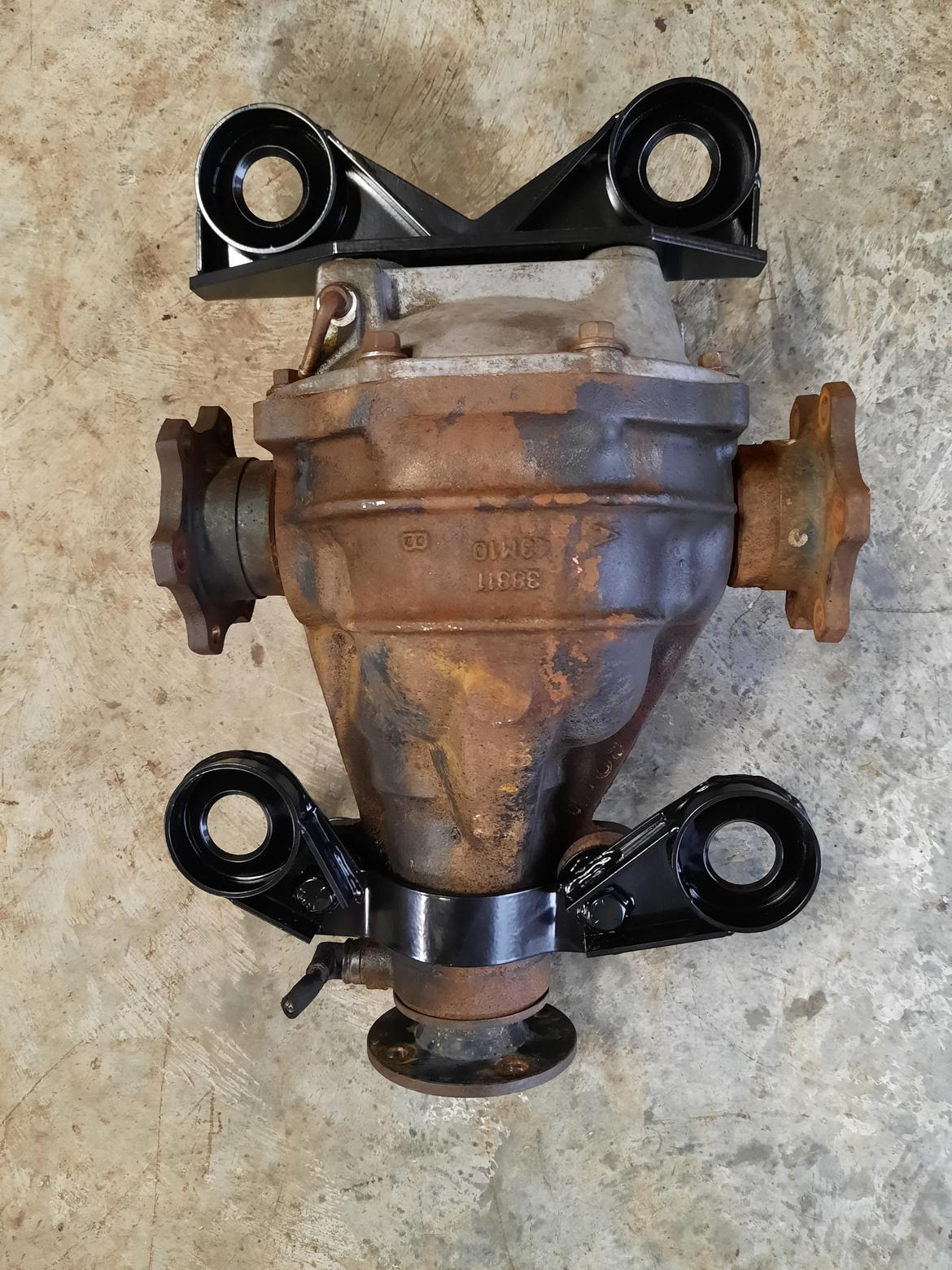
I know that I will need to get the diff setting higher than the TR6 conversion was designed for in order to clear a lower frame tube (see TVR Scott's thread, if you haven't been following along), but I'm thinking that since I'm using the TVR (TR6) drive shaft, I'll be reducing the radius of the input shaft mount by over 1/4". That means that I won't need the diff raised by the 3/4" that Scott found he needed. I'm thinking I can get the required clearance another way...
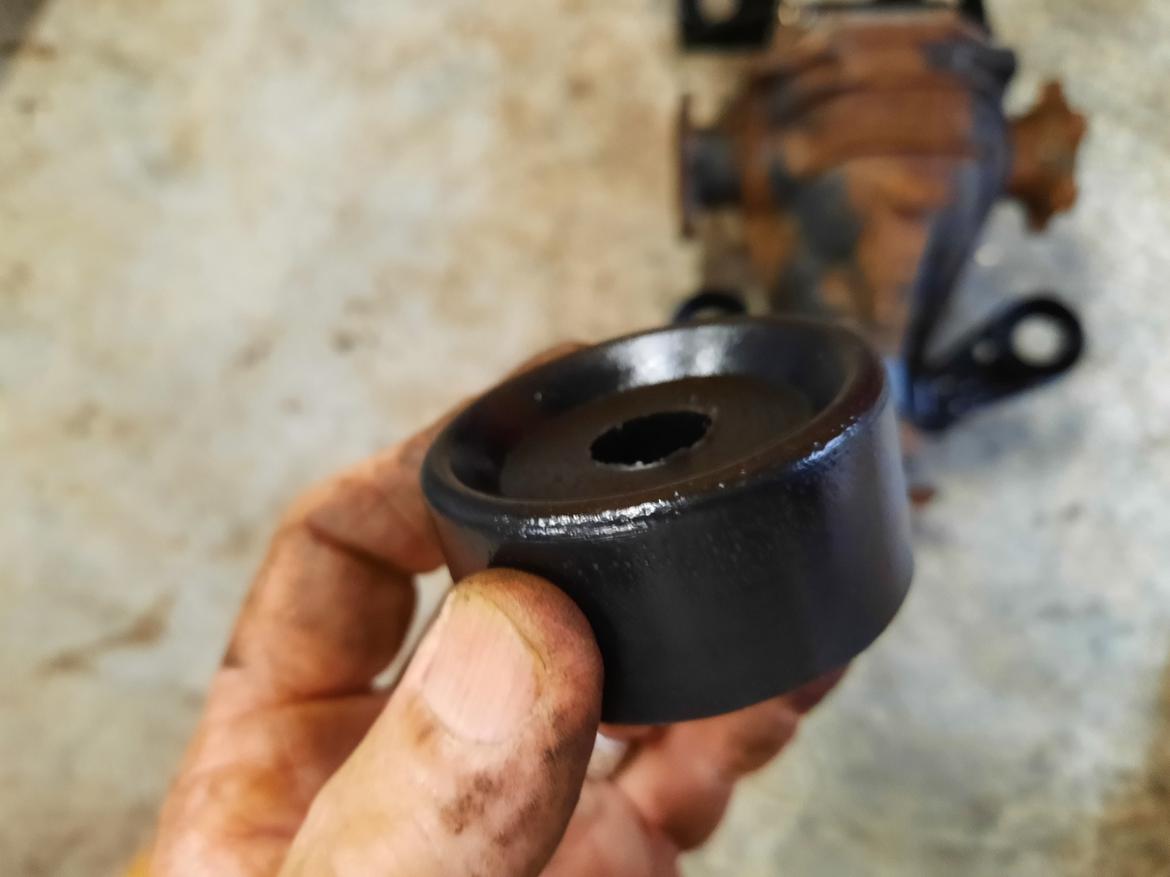
This is what the upper mount bushings look like... basically a polyurethane "puck" with a concave bottom (I'm holding it up side down). It"s about a full inch thick, with a recess of less than 1/4".
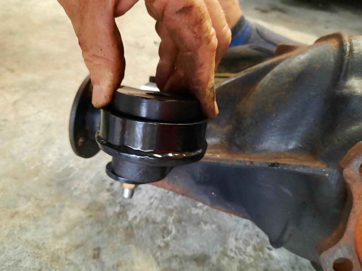
Here's how it fits in the mount. I looks to me like I could cut it down by at least 1/2", which would raise the diff by the same distance, which I think would give me the clearance I need for the input driveshaft. Tomorrow I'll call Richard Good and see if there might be any unforeseen (by me) problems with what I'm proposing. I think this, combined with the smaller diameter driveshaft and u-joint should work!
De-ja-vu here.
I'll go out on a limb and say decreasing that bushing height it's going to be enough. I had my R200 rough-installed with all stock parts and no bushings and it didn't fit.
Also, throw some padding on the frame tubes so you don't bang them up.
And there's a couple casting features on the bottom that will need to be ground off.
Blah blah blah. You've seen my thread...
In reply to TVR Scott (Forum Supporter) :
I'll assume you meant "isn't" going to be enough by the tone of of your post. You're probably right, but I'm an incurable optimist. I have studied your thread, repeatedly. I don't recall you mentioning any castings on the bottom though. I'll have to go back and read it again.

JoeTR6
Dork
11/12/20 8:11 a.m.
One concern with this approach is that the poly bushings are already quite firm. Reducing the bushing thickness will make them firmer. That would probably cause trouble with TR6 diff mounts (which are notoriously weak), but I'm not sure about the TVR mounts.
If you can try this out without ruining the mounts, it's worth a try. Or just buy another set of mounts if it doesn't work out.
In reply to JoeTR6 :
Thanks for your input, Joe. Actually, though, there are no Triumph parts used in this conversion, and the Goodparts seem to be pretty solid units. I was more worried about the "isolation" factor in reducing the thickness of the "isolator bushings".I'll try it without any bushings, like Scott suggested, and see if it will get the clearance I'm hoping for.
In reply to Stu Lasswell :
Yeah, try it. Maybe our two short-run classic British sports cars are somewhat different.
Casting "nubs" to remove on the bottom are shown here. You can see the two ground-down areas along where the back cover bolts up.
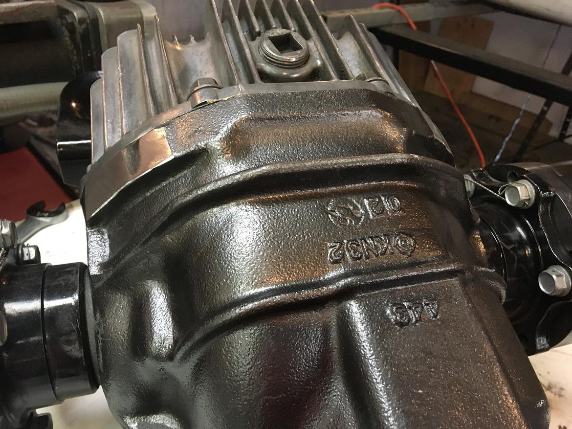
On the top left, there's this ear that needs to come off:
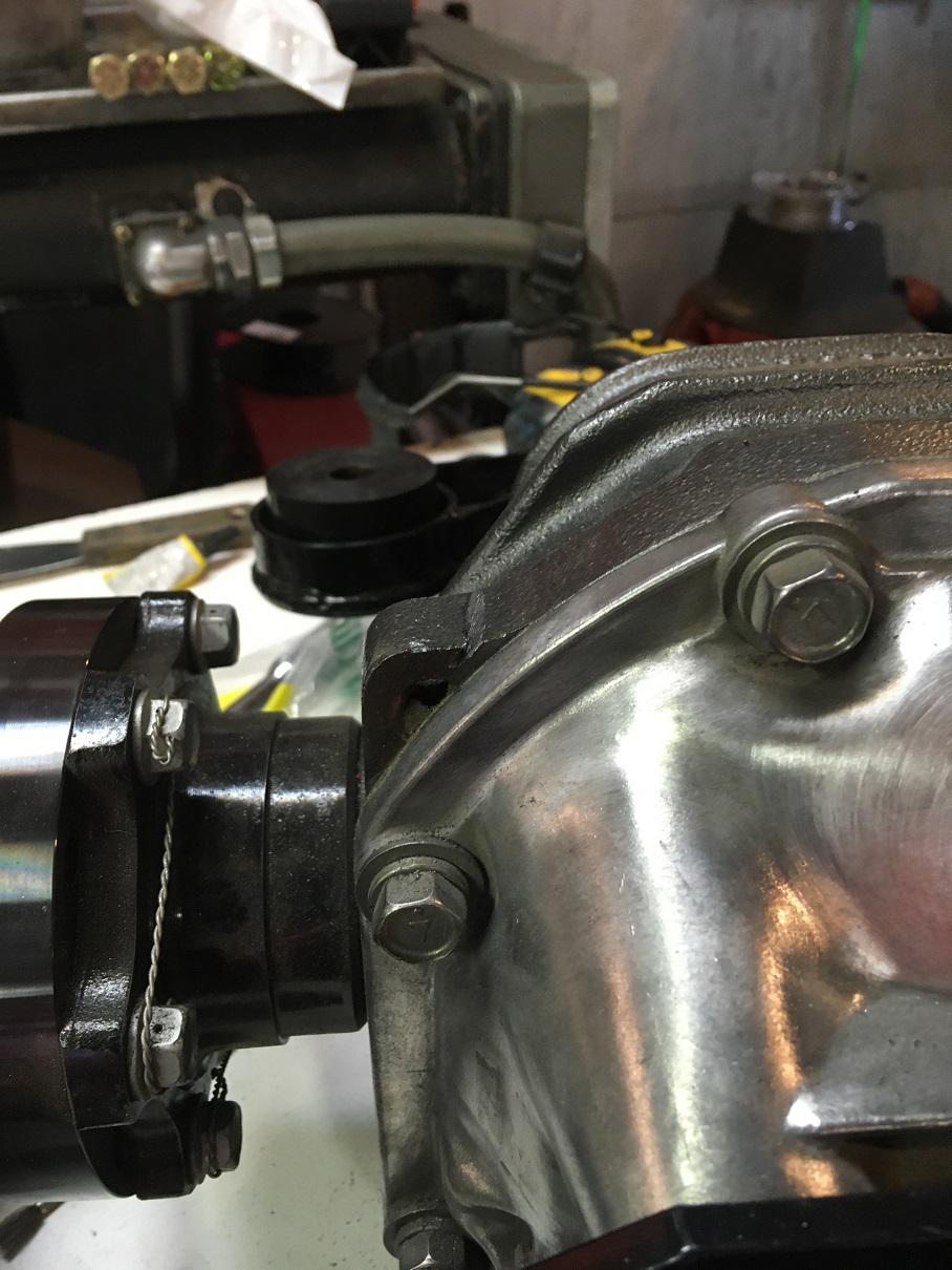
And since you've got the grinder out, go ahead an knock down this lump on the front. This one doesn't need a lot, but it looks nice and clean if you grind it down parallel.
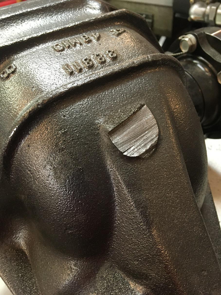
In reply to TVR Scott (Forum Supporter) :
Thanks, Scott. I knew about the lump on top, but not the ear or lumps on the bottom. I'm sure that they would have become obvious eventually, but I'd rather just go ahead and grind them off ahead of my fitment attempt.
Well, as per Scott's recommendation, I got out the angle grinder and went to work on the various protrusions on the diff case. I still have hopes of not having to resort to cutting and welding in order for this conversion to happen. To that end, I took the original TVR/Triumph drive shaft and centered it on the input mount to see how much will be cut off... damned if it isn't almost a full inch in diameter! That's nearly a half inch of clearance right there.
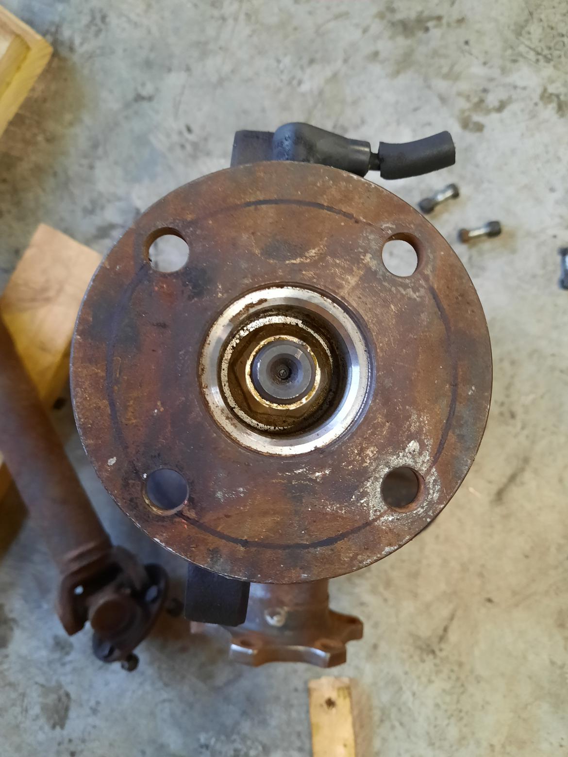
You can see the scribed line made with a Sharpie. I'll go ahead and try fitting the diff as is, and hopefully this difference plus shaving the upper isolator will do the trick! (As I said, I'm a consummate optimist). Then I'll remove the input flange and have the required modifications done.
Ah. That's what you're up to. Maybe you will be fine after all.
So you're going to redrill the input flange on the R200 for the original driveshaft? Just make sure you get it concentric...
In reply to TVR Scott (Forum Supporter) :
Oh yeah, I'll have a professional do it, as well as shorten, balance and refurbish the driveshaft.
When I did my R200 conversion in a Triumph TR4A, I kept the Nissan flange intact and just had a driveshaft made up that was Nissan on the rear and Chevy T5 on the trans side. Since you already have to do a driveshaft anyway, that might save you some time and money if the input flange clears everything on your TVR.
In reply to dherr (Forum Supporter) :
IF the input flange clears. That's the big issue, and I'm expecting the reduction of the radius to match the driveshaft to be a big factor in NOT modifying the frame or sub-frame like Scott did. The driveshaft needs to be shortened and "freshened" anyway, so I hope the additional machining won't add too much to the expense, vs. a custom built driveshaft. And I really want to avoid a cutting/welding project, as I don't have the skills or equipment (like Scott) so that job would have to be farmed out as well.
Those input flanges are interchangable among other Nissan/Infiniti models using the same type diff. We changed the input flange on a 350z diff to an Infiniti style for our Challenge Q45. Just don't install the new flange with an impact. My old teammate did that before I could stop him. No bueno.
In reply to Stampie (FS) :
I would imagine any alternate flange for that diff will be the same diameter, but that might be an avenue to pursue. As to installing the flange, Goodparts says to mark the flange, nut and housing with paint and align and tighten only to realign and no further.
But hey, I appreciate y'all making comments... it lets me know somebody out there is still following along with my build!
In reply to Stu Lasswell :
There's actually a torque spec. IIRC it's like 150 ft/lbs but don't hold me to that. You have to lock down the output flanges of course. I would look at the Nissan trucks from that era and see if they are smaller. Ebay pictures are great for that.


 That’s why I plan to add a top stiffening bracket, similar to Mike Zappa’s. From what I remember, if you try to adjust the rack height only, you end up having to cut the rack mounting perches. This is the more tunable solution. I may be wrong, but I see fewer drawbacks doing it this way.


